Week -2
Aim of the project
- To make a Simulink model of Doorbell using a solenoid block with a holding time of 2seconds.
- To make a Simulink model of a Thermistor sensed temperature of a heater and on-off condition of fan with varying temperature condition.
The objective of the project
- To describe the Simulink model of doorbell with the clear analysis of output.
- To describe the Simulink model of thermistor based fan switching control of a heater
Software Used
MATLAB R2020a –Simulink
Body of the content:-
- Doorbell using solenoid block
While switching on the electric bell the electromagnet in the bell will magnetize and pull the hammer towards the bell and a sound will produce due to this hitting
Simulink model of the Doorbell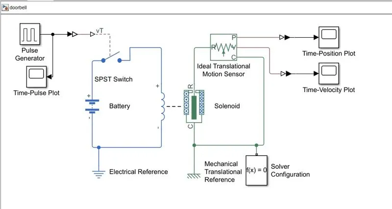
Simulink Blocks used
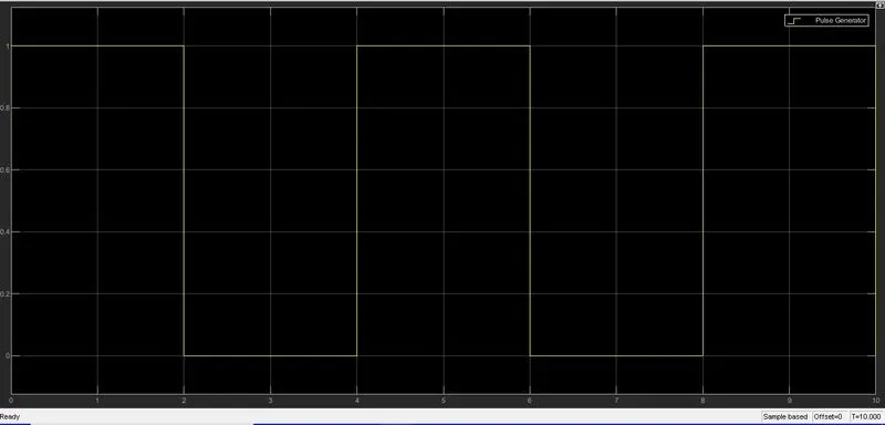
- Pulse Generator – Generate pulse to make the switch to on state. Parameters configured are pulse type is time-based, time (t) is selected as use simulation time, amplitude =1, Period =4, Pulse width (% of period) =50, with a phase delay of zero.
- Simulink-PS Converter –Converts Simulink System Signal to Physical System Signal.
- SPST Switch – Single Pole Single Throw switch to control the power supply from the source.
- Battery –To provide electrical supply to the solenoid.
- Solenoid –This is to move the hammer towards the bell to make a sound.
- Electrical reference –This is to make all electrical blocks grounded.
- Ideal Translational Motion Sensor –to sense the motion of the hammer with its velocity and position.
- Scope – To plot (Time – Velocity, Time –Position, Time –Pulse) graph.
- PS-Simulink Converter –Converts the Physical system signal to Simulink System Signal.
- Mechanical Translational Reference – Is used to make all mechanical blocks grounded.
- Solver Configuration – Defines solver settings to use for simulation.
Pulse Generator Output with respect to Time (Controlling signal of SPST)
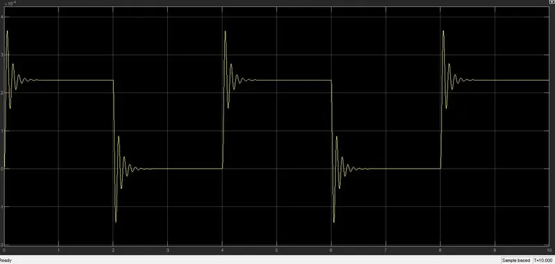
Position Plot with respect to Time
Velocity Plot with respect to Time
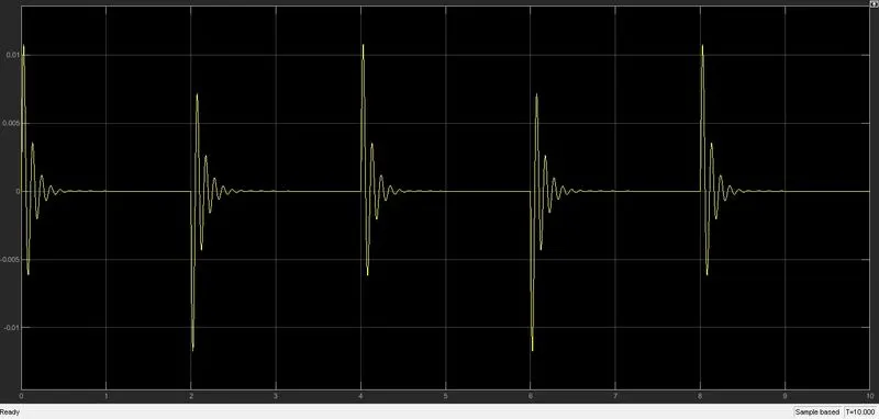
Output produced by the pulse generator is more than that of the threshold value of SPST Switch and it changes position to close, due to this action of the switch the solenoid gets magnetized and the hammer hits the bell in the holding time of 2Seconds and it's repeating the action up to the stop time.
- Thermistor based heater fan controlA thermistor is one type of resistor whose resistance is strongly dependent on temperature, thermistors are widely used as inrush current limiters, temperature sensors (Negative temperature coefficient or NTC type), here thermistor used as a temperature sensor depends upon the value sensed by the temperature the fan start running at a minimum temperature of 25degree Celsius (298Kelvin). Applied temperature is 20degree Celsius at the time interval of 0-10Seconds,27degree Celsius at the time interval of 10-30Seconds and 23degree Celsius at the time interval of 30 to 50Seconds.
Simulink model of thermistor based heater fan control
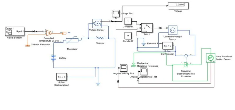
Blocks used
- Signal Builder-Used to provide selected inputs signal.
- Controlled Temperature Source- it represents an ideal energy source in a thermal network that can maintain a controlled temperature difference regardless of heat flow rate. The temperature difference is set by the physical signal port S. A positive temperature difference causes the temperature at port B to be greater than the temperature at port A.
- Thermistor-This block represents an NTC thermistor using the B-parameter equation. The resistance at temperature T is given by R(T) = R0*exp(B*(1/T-1/T0)) where R0 is the Nominal resistance at the reference temperature T0, and B is the Characteristic temperature constant. The temperature T of the thermistor is governed by the equation m*c*dT/dt = Q where Q is the net heat flow into port A, m is the mass and c is the lumped specific heat capacity. The thermal mass m*c is calculated from the Thermal time constant t_c and the Dissipation factor K_d using the equation m*c = K_d*t_c.
- Voltage Sensor-It is a device that converts voltage measured between any electrical connections into a physical signal proportional to the voltage.
- Resistor- It is connected to measure the voltage with a minimal connected load. Resistance has a constant value.
- Controlled Voltage Source-It’s an ideal voltage source that is powerful enough to maintain the specified voltage at its output regardless of the current passing through it
- Switch-it will give continuity at once it reaches its threshold value.
- Ideal Rotational Motion Sensor-it is a device that converts an across variable measured between two mechanical rotational nodes into a control signal proportional to angular velocity or angle. The sensor is ideal since it does not account for inertia, friction, delays, energy consumption, and so on
- Electrical Reference- To ground the electrical model
- Thermal Reference-This represents a reference point in a thermal network where the temperature is equal to absolute zero.
- Mechanical rotational reference-represents a mechanical rotational reference point, that is, a frame or ground.
- 12)Rotational Electromechanical converter-Provides an interface between the electrical and mechanical rotational domains. If the current and voltage through and across the electrical ports are I and V, and the torque and angular speed through and across the mechanical ports are T and w, then T = K*I, V = K*w, where parameter K is the Constant of proportionality with equivalent units of Nm/A or V/(rad/s). Both the torque and back emf equations having the same value of K represent a lossless electromechanical energy conversion.
- Solver configuration-Defines solver settings to use for simulation.
- Simulink –PS converter-converts the Simulink input signal to a Physical Signal.
- PS-Simulink Converter -Converts the input Physical Signal to a Simulink output signal.
- Display-to display the voltage value
- Scope-To plot the values of temperature, voltage, velocity, angular displacement
- Constant-Provides a constant value input.
Temperature with respect to Time Plot
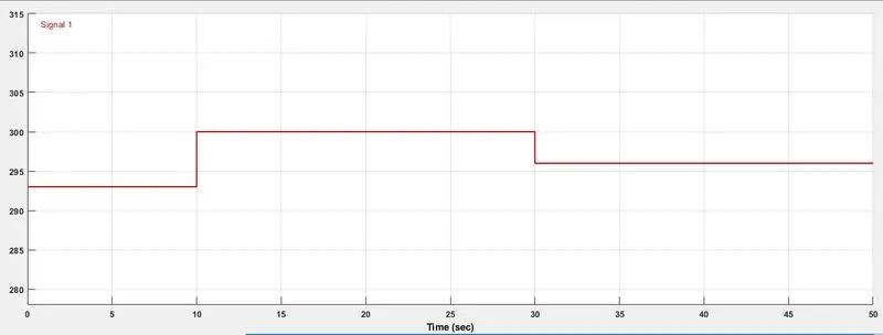
Input signal given to the controlled temperature source is 293(for 20 degree Celsius)up to 10 seconds,300(for 27 degree Celsius) from 10Sec to 30Seconds,296(for 23 degree Celsius)from 30Sec to 50 Seconds.
Voltage With respect to Time Plot
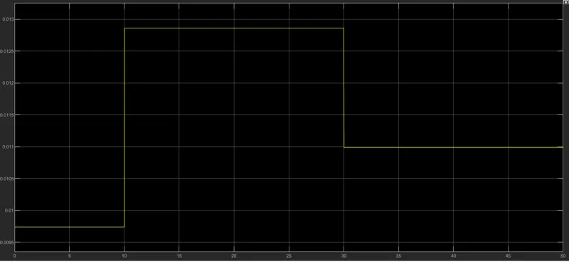
Voltage measured by the Voltage sensor as shown in the time voltage plot
Velocity Plot with respect to Time
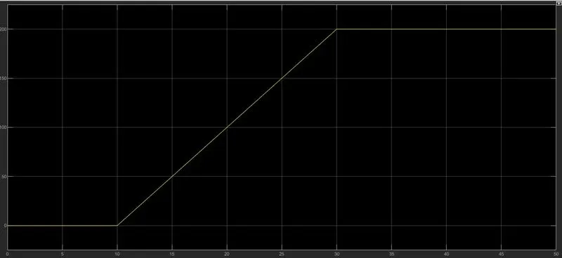
Angular displacement Plot With respect to Time
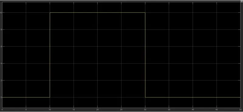
The Status of the fan up to 50 Seconds, as shown above, the initial angular displacement of the fan is zero(up to 10 Seconds it remains same due to its temperature value is below 25 degree Celsius ) after the 10 seconds its starts due to the temperature reaches 27 degree Celsius it's more than enough to start the fan. After 30 seconds the fan's angular displacement reaching zero due to the temperature reaches to 23 degrees Celsius(296 Kelvin).
Conclusion
Simulink model of doorbell with solenoid and thermistor-based heater fan control is created with the required conditions.