Week-7 Challenge: DC Motor Control
AIM - To study and explain the example model "Speed control of a DC motor using BJT H-bridge" and comment on the armature current shoot-up from the scope results and to compare the model "The Four-Quadrant Chopper DC Drive (DC7) block" with H bridge model.
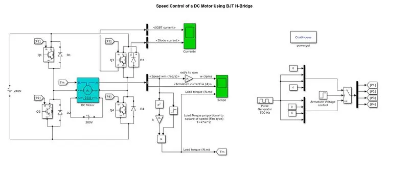
1. A. Explain a MATLAB demo model named ‘Speed control of a DC motor using BJT H-bridge’.
B. Comment on the armature current shoot-up from the scope results.
C. Refer to the help section of ‘The Four-Quadrant Chopper DC Drive (DC7) block’. Compare it with the H-bridge model.
 |
A.
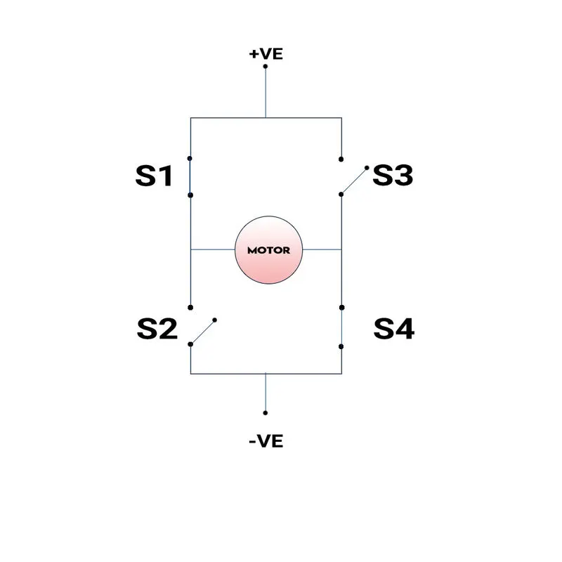
H-BRIDGE - It is an electronic circuit which helps us to apply voltage to load in both direction. The below figure shows us the basic circuit of the H-Bridge. Below images were created using photoshop.
|
When S1 and S2 are ON, The DC motor runs in a clockwise direction. |
|
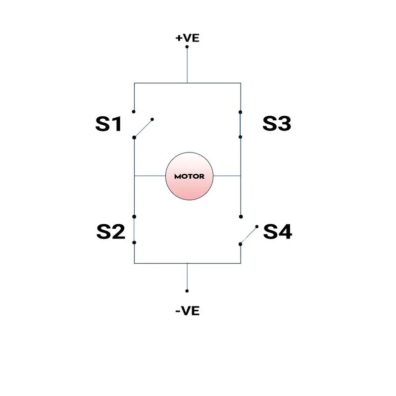 When S2 and S3 are ON, the DC motor runs in an Anti-clockwise direction.
BJT -
 |
BJT is abbreviated as Bipolar Junction Transistor, which is a semiconductor switch. The Bipolar Junction Transistor (BJT) operates as an IGBT when used for power switching applications.IGBT has three terminals gate, collector, emitter.PWM control signals are given through the gate terminal. we can turn ON/OFF the transistor by giving a control signal through the gate terminal.
DIODES -
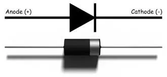 |
A diode is an uncontrolled turn ON/OFF the device. As we know diode is a one-way switch that conducts current in forward biased direction and acts as an insulator in reverse biased direction. the diode has a PN junction where the P junction has vacant holes for electrons. The N junction has excess electrons and between the P and N junction, there is a depletion layer containing both holes and electrons has voltage drop between 0.5 - 0.8V. Diodes in forward biased direction conduct only when the voltage is more than 0.8v.In reverse biased direction, the depletion layer becomes wider and acts as an insulator. here the diodes D1, D2, D3, D4 are freewheeling diodes. It avoids problems due to negative voltage produced by the back emf of the dc motor.
DC MOTOR -
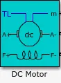 |
An electric motor that runs on a direct current is called a DC motor, It converts electrical energy into mechanical energy. It works on the principle of electromagnetic induction, the current-carrying conductor placed in a magnetic and electric field experience a force.
In the above block of DC motor,
TL - Mechanical Load torque input
m - it is an output block containing measurement signals
A- armature circuit terminals
F- field terminals of the DC motor
we can control the speed of the motor by controlling the voltage of the dc motor, controlling the voltage can be done by controlling the transistor control signal where the control signal given by the PWM generator.
PWM Generator -
 |
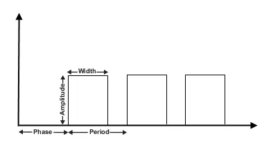
the PWM generator generates square wave signals at regular intervals.
 |
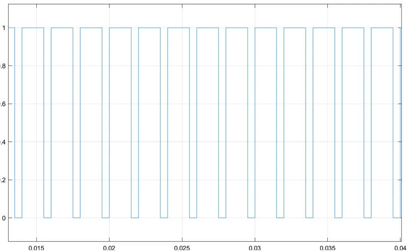 |
the main aim of this PWM generator is to vary the width of this waveform and thereby varying the average DC voltage applied to the terminals of the motor or any other load such as LED. By changing or modulating the timing of these pulses the speed of the motor can be controlled.
In general, the longer the square wave is in the ON position(1) the faster the motor will rotate.
for example - suppose we have a 100v battery connected with a transistor and a dc motor and the control signal for the transistor is given by the PWM generator but we only need to give the battery only 10v, this can be done by changing the duty cycle to 10%. That is, if the transistor is turned ON for 1 unit of time then the transistor has to be turned OFF for the remaining 9 unit of time.
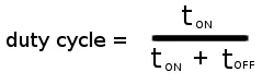 |
Average voltage = 100*(10/100)= 10V
| average voltage = total battery capacity * duty cycle |
SWITCH -
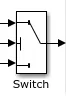 |
this switch consists of three ports, the first port is the input data port and the second port is the control signal port and the third port is another input data port. The first port and third port are controlled according to the condition given to the second port.
EXPLANATION -
First of all, the control signal for the BJT transistor is given through a PWM generator, whereas explained earlier, the speed of the motor depends on the voltage given to the DC motor and where voltage supplied to the motor depends is controlled using switching ON/OFF of the transistor and the switching commands are given by the PWM control signals. To alter the control signal we have to alter the duty cycle.
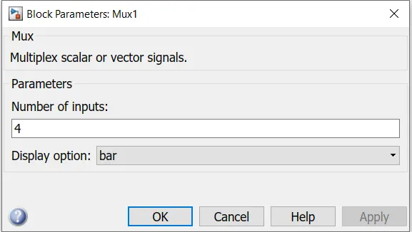
PWM Generator is connected to two 4-input multiplexer blocks. whereas out of 4 inputs 2 inputs were given value as 0 using constant block. The multiplexers combine the inputs and the combined inputs are given to the switch.
 |
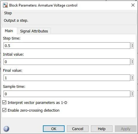
where the switch's control port is connected to an armature voltage control block with a step time of 0.5sec.
 |
the switch is connected to a demultiplexer with 4 output port. the 4 outputs were given to the transistor gate terminal using goto and from blocks. when the transistor Q1 and Q4 are turned ON, the motor runs in a clockwise direction and the diodes D1 and D4 acts as a freewheeling diode, similarly, when the transistor Q2 and Q3 are turned ON, the motor runs in an antilock wise direction. and the diodes D2 and D3 act as freewheeling diode. therefore the DC motor speed can be varied by changing the voltage from 0 to 240v by changing the duty cycle from 0 to 100%.
B. Comment on the armature current shoot-up from the scope results.
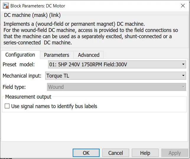
DC Motor with specification(5HP, 1750RPM,240V,field 300v)
 |
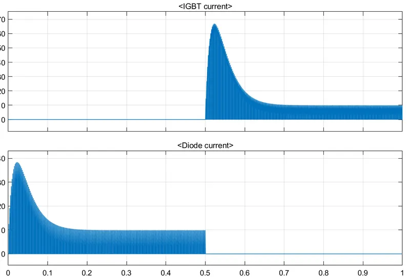 |
According to the control signals given to IGBTs initially from 0 to 0.5seconds transistors Q1 and Q4 were activated and the above graph is the result of transistor Q3 which was in the off condition that's the reason why for the first 0.5 seconds there was no current. After 0.5seconds the transistor Q3 got switched ON and as a result, the current started flowing as shown in the above graph. similarly, In the above graph, the second portion is the result of the diode D3, Once the motors started running the current passes through the circuit, as a result, there is an indication in the graph. after 0.5 seconds the current flows in the reverse direction so there is no indication in the diode current graph.
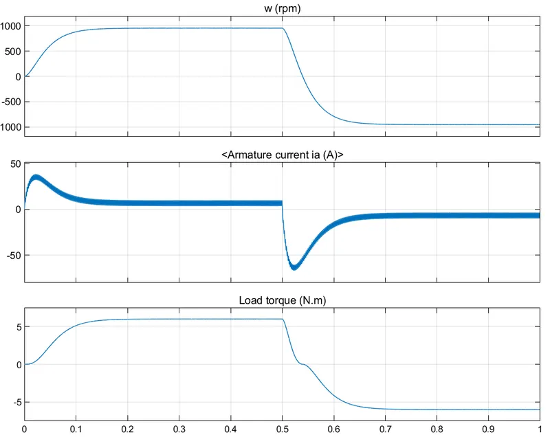 |
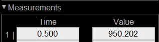
In the above graph, initially, the motors run from 0 to 950.202 rpm in 0.1 seconds.
 |
After 0.5 seconds according to the condition given to switches by the armature voltage control block, the other two transistors got activated and the motor started to run in the anti-clockwise direction.
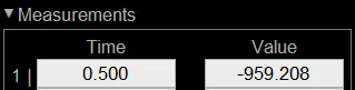 |
after 0.5seconds the motors rotate in the reverse direction in -959.208 rpm till 1 second.
Once the motors starting rotating the armature current shoots up and reduce to 6.46A because of constant rpm.
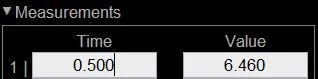 |
after 0.5seconds the motor changes its direction, the armature current suddenly overshoots because of the high duty cycle and load, to reduce the sudden overshoot we can reduce the duty cycle and after the sudden overshoot, the armature current is -6.506A.
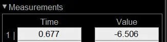 |
C. Refer to the help section of ‘The Four-Quadrant Chopper DC Drive (DC7) block’. Compare it with the H-bridge model.
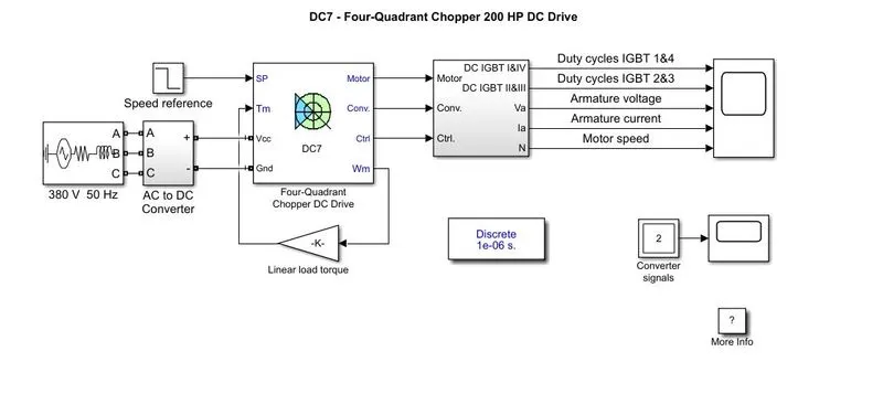 |
As the name implies, the four-quadrant chopper DC drive works in four quadrants namely (quadrant-1 forward motoring), (quadrant-2 forward braking), (quadrant -3 reverse motoring), (quadrant-4 reverse braking).
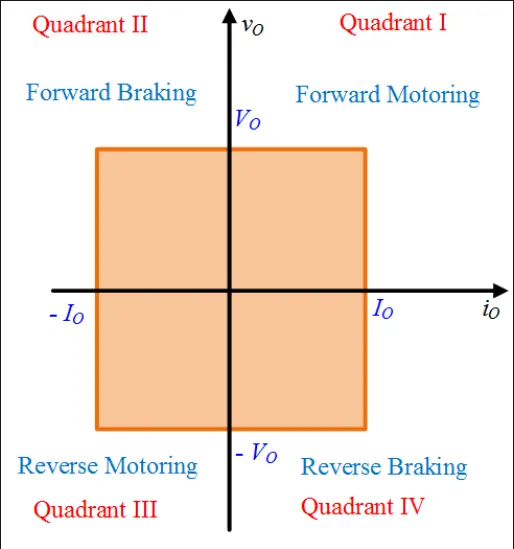 |
In quadrant 1 the voltage and current are in the same direction as the supply voltage is given to the motor, the motor is in motoring operation, and it is said to be forward motoring. In quadrant 2 regenerating braking concept takes place, this happens when the direction of current changes and voltage direction remains the same and it is said to be forward braking. In quadrant 3 the voltage and current direction change simultaneously, which is results in the motor rotating in the opposite direction. which is said to be reverse motoring. In quadrant 4, the direction of the voltage changes while the direction of the current remains the same. which results in negative regenerative braking. which is said to be reverse braking.
COMPARING FOUR-QUADRANT CHOPPER DC DRIVE AND H BRIDGE
| FOUR QUADRANT CHOPPER | H-BRIDGE |
|
|
|
|
|
|
|
|
|
|
|
|
|
|
RESULT - explained the example model "Speed control of a DC motor using BJT H-bridge" and explained the armature current shoot-up from the scope results and finally compared the model "The Four-Quadrant Chopper DC Drive (DC7) block" with the H bridge model.
2. Develop a 2-quadrant chopper using Simulink & explain the working of the same with the relevant results.
TYPE-C TWO-QUADRANT CHOPPER -
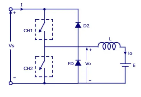 |
QUADRANT 1 - When CH1 is switched ON, the current flows from source to inductor load, which stores the energy. Then when CH1 is switched OFF, the energy stored in the inductor load flows through the battery and then diode in a loop. then the output voltage is equal to Vs.here we can see that both current and voltage are in a positive direction.
QUADRANT 2 - When CH2 is switched ON, the load current (i0) will become be reversed.As diodes do not conduct a negative voltage supply. we can see that the current is negative and the voltage remains the same. now when CH2 is turned OFF, the inductor will release its energy through diode d2.
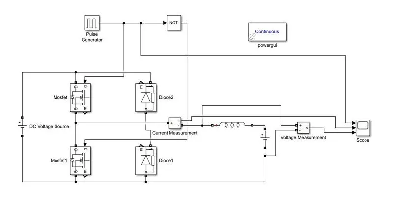
SIMULATION DIAGRAM -
 |
SIMULATION RESULTS -
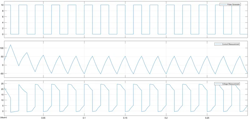 |
- The control signal for the MOSFET is given through a pulse generator with amplitude as 10v and time period as 0.02seconds and pulse width is set to 50 because MOSFET 1 will be turned ON for 50% of the time and similarly MOSFET 2 will be turned ON for remaining 50% of the total time.
- As both should not be switched ON simultaneously, therefore, a control signal for one of the switches is inverted using NOT operator block.
- The main DC voltage source has 24V voltage and the second DC voltage source has 12V voltage.
- According to the control signal from the pulse generator, the MOSFET 1 is switched ON, the current flows from source to inductor load, which stores the energy. Then when MOSFET 2 is switched OFF, the energy stored in the inductor load flows through the battery and then diode in a loop. then the output voltage is equal to Vs.here we can see that both current and voltage are in a positive direction.
- According to the control signal from the pulse generator, the MOSFET 2 is switched ON, the load current (i0) will become be reversed. As diodes do not conduct a negative voltage supply. we can see that the current is negative and the voltage remains the same. now when CH2 is turned OFF, the inductor will release its energy through the diode.
MODEL LINK - Click here to check out my simulink model
RESULT - Developed a 2-quadrant chopper using Simulink and explained its working with the relevant results.
3. Explain in a brief the operation of the BLDC motor.
BLDC MOTOR - Abbreviated as Brushless direct current Motor, As the name implies it is a motor that does not have brushes, unlike traditional DC Motor having mechanical commutation, the BLDC Motor has Electronic commutation.BLDC motor has only two basic parts ROTOR and STATOR where the rotor is a permanent magnet and the stator is a coil arrangement.
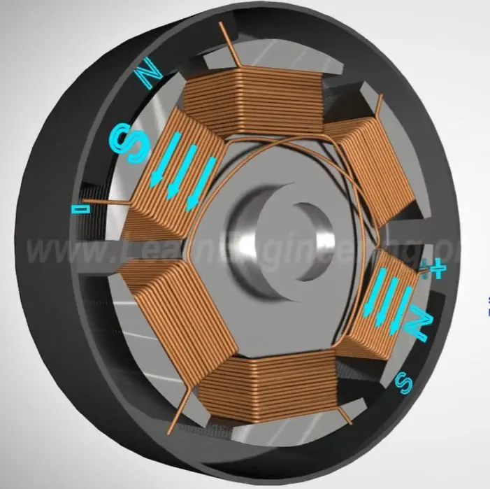 |
By applying the dc power to the coil, the coil will energise and become an electromagnet. the basic working operation of a BLDC is based on the simple force interaction between the electromagnet and permanent magnet. In this condition, when coil A has energised the opposite poles of the rotor and stator is attracted to each other. as the rotor nears coil A, coil B is energised, as the rotor nears coil B, coil C is energised, After that coil is energised with the opposite polarity. this process is repeated and the motor continues to rotate. This is the simple working principle of the BLDC motor. the process is less efficient because only one stator winding is energised at once,
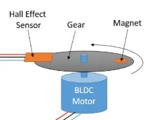 |
To overcome this we can energise the stator winding in a sequence and the position of the rotor must be known to precisely energize a particular set of stator windings. therefore a position sensor known as a hall sensor is used to detect the position of the rotor and transform it into an electrical signal.
ADVANTAGES -
- Low maintenance because of the absence of brushes
- high efficiency
- less noise
- higher RPM
- cost-efficient
RESULT - Briefly explained the operation of the brushless dc motor.
REFERENCE -
- https://www.electricaltechnology.org/2016/05/bldc-brushless-dc-motor-construction-working-principle.html
- https://skill-lync.com/projects/multi-quadrant-operation-of-dc-motor-in-simulink
- https://www.electrical4u.com/brushless-dc-motors/
- https://www.youtube.com/watch?v=bCEiOnuODac
- https://www.youtube.com/watch?v=VaWGJVHiJC8&ab_channel=JAESCompanyJAESCompany