Doorbell and Heater model using simulink
1-
AIM - Make a Simulink model of Doorbell using solenoid block
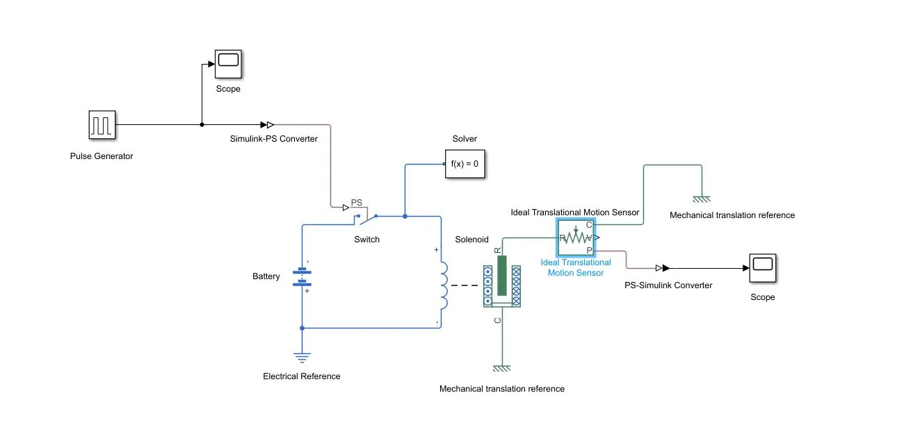
COMPONENTS REQUIRED - Solenoid, Ideal Translation motion sensor, Mechanical translation reference, Battery, Switch, Electrical reference, Pulse generator, Scope, Display.
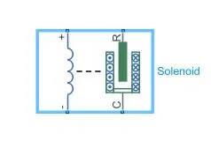
1- Solenoid- Solenoid is a device that generally converts electrical energy into mechanical energy. the plunger between the coils can be pulled in by the electromagnetic field as soon as the current starts flowing through the coil. when we cut the power supply the spring attached to the plunger pushes the plunger back to its original position.
 |
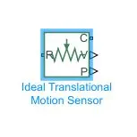
2- Ideal Translational Motion Sensor - This block measures velocity or displacement in a mechanical translational network. The sensor is ideal because it does not account for inertia, friction, delays, energy consumption, and so on. port R(positive probe) and C(reference) are connected to the block whose mechanical translation is to be monitored. port v and p are signal output ports for velocity and positions respectively.
 |
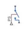
3- Switch - The Switch block models a switch controlled by an external physical signal (PS). If the external physical signal PS is greater than the value specified in the Threshold parameter, then the switch closed, otherwise, the switch is open. The external physical signal is taken from the pulse generator.
 |
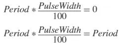
3- Pulse Generator - Pulse Generator generates square waves at regular intervals with specified parameters such as Amplitude, Period, pulse width, phase delay. In time-based mode, it shows error even if one of the below equation is True. therefore pulse width can't be 0 or 100. I have taken a phase delay of 2secs because the switch is closed for 2secs, amplitude as 1, a period as 4 secs, pulse width as 50% of 4secs.
 |
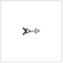
4- Simulink-PS Converter - Converts the Simulink input signal to a Physical Signal.
 |
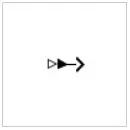
5- PS -Simulink converter - Converts the input Physical Signal to a Simulink output signal.
 |
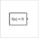
6- Solver- Each physical network represented by a connected Simscape™ block diagram requires solver settings information for simulation. The Solver Configuration block specifies the solver parameters that your model needs before you can begin the simulation.
 |
BLOCK DIAGRAM-
 |
RESULTS -
 |
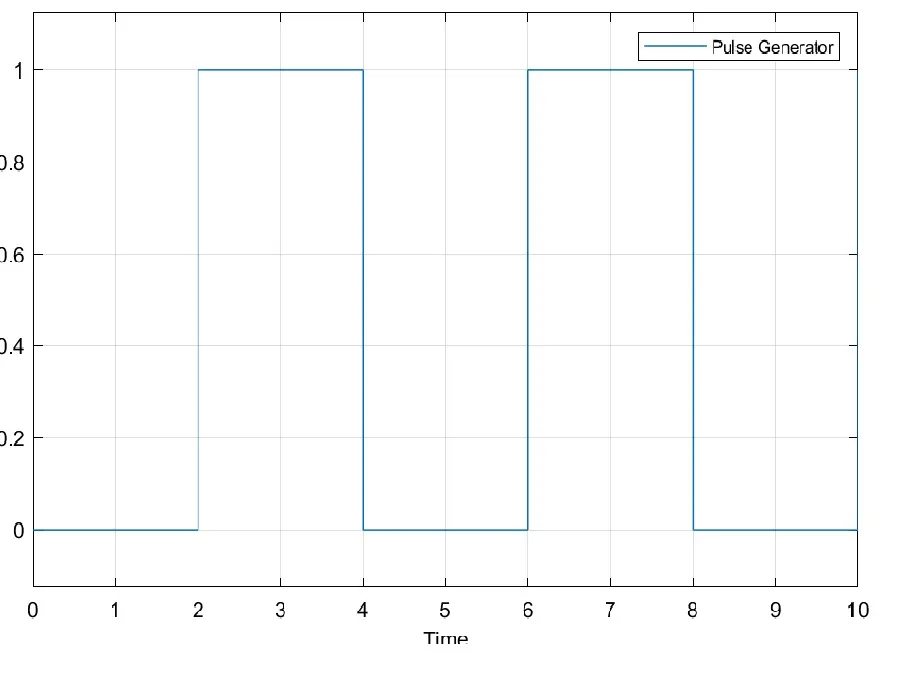 |
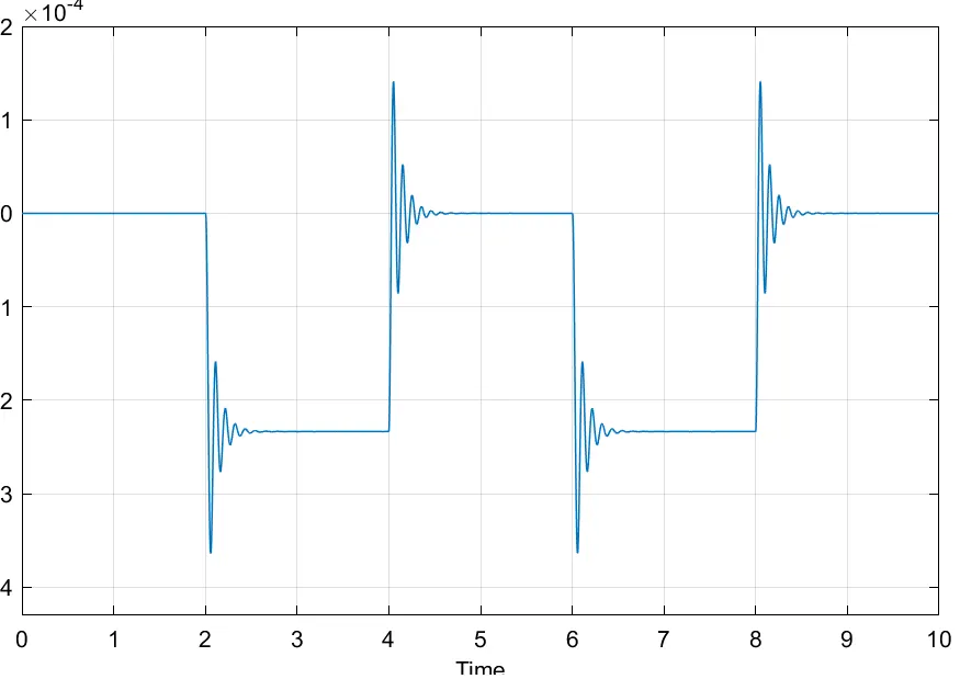
The simulation ran for 10sec and for each 2sec interval the bell rang.
2.
AIM - Use a thermistor to sense the temperature of a heater and turn ON if the temperature above 25 °C else OFF.
COMPONENTS REQUIRED - Thermistor, controlled temperature source, Repeating Sequence stair, solver, thermal reference, resistor, voltage sensor, battery, electrical reference, constant, switch, scope.
- THERMISTOR - Thermistor sensors are used as temperature sensors.they are mainly used in digital thermometers. Port A is a thermal port and thermistor is a type of resistor whose resistance depends on temperature.
- CONTROLLED TEMPERATURE SOURCE - Controlled temperature source is an ideal energy source in a thermal network that can maintain a controlled temperature difference regardless of the heat flow rate.
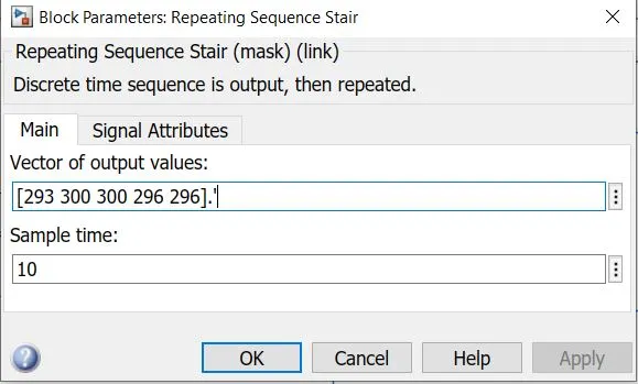
- REPEATING SEQUENCE STAIR - As the name specifies its output repeats the stair sequence which we can specify in vector form. The input I have taken is [293 300 300 296 296].' and the sample time is 10secs and the whole simulation time is 50secs.
- VOLTAGE SENSOR - it is used to calculate and monitor the amount of voltage in an object. v port is the Physical signal output port for voltage.
- SWITCH - This is used to provide switch condition, port 1 and port 2 are data input whereas port 3 is control input signal.
BLOCK DIAGRAM -
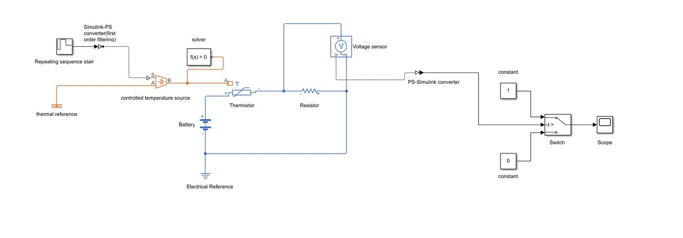 |
WORKING - The input signal is taken from repeating sequence stair as [293 300 300 296 296].' here instead of repeating sequence stair we can also use signal builder and sample time is taken as 10secs and whole simulation time is taken is 50secs and this signal is given to controlled temperature source and that controlled temperature source output is given to thermistor. The voltage sensor is connected across a resistor to detect the different temperature changes. The switch block receives a signal from the voltage sensor and executes the conditions given in port1 and port3.
 |
RESULTS -
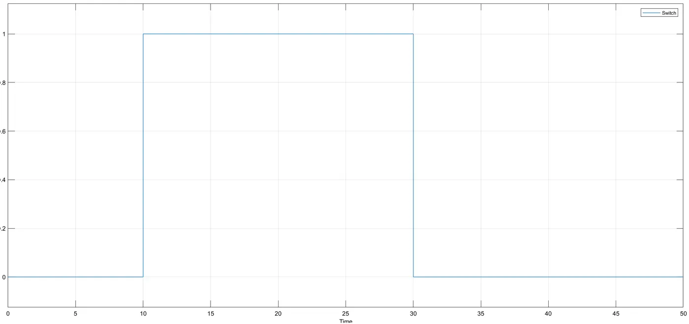 |
initially, for 0 to 10 secs, the temperature is 20-degree Celsius or 293k the fan is in the OFF position. Once the temperature crosses 25-degree Celsius or 298k the fan get to ON position. Again during 30 seconds the fan automatically turns off as shown in the above graph.