Week-7 Challenge: DC Motor Control
Week-7 Challenge: DC Motor Control
Problem Statement- 1: Run MATLAB demo ‘Speed control of a DC motor using BJT H-bridge’. Modify the model such that the armature current doesn’t shoot up when the motor changes direction from forward to reverse.
Answer: The model for the 'Speed control of a DC Motor using BJT H-bridge' can be found in the Matlab documentation. The H-Bridge produces a chopped voltage of the input voltage and by doing that; it controls the speed of the DC motor. As the name suggests, it uses a BJT (Bipolar Junction Transistor which is a type of transistor that uses both electrons and holes as charge carriers, hence the name bipolar. Other transistors like FETs (Field Effect Transistors) are unipolar transistors meaning that they only use one type of charge carrier(either electrons or holes). BJTs are used for switching and amplifying applications.
BJTs have 3 terminals which are: the collector (C), the base (B), and the emitter (E). Current flows in only the emitter and the collector and the amount of current that flows through them is controlled by the base. BJTs use semiconductors in their work, and so there are 2 types of BJT: NPN type and PNP type. The discussion of their working principles is not needed here so that part is skipped here intentionally. However, The circuit symbols are shown below:
BJT H-Bridge: Now, it is important to observe that in the model it is the IGBTs that are used instead of BJTs. The Bipolar Junction Transistor (BJT) when used for power switching applications, operates as an IGBT. When it is conducting i.e. in the saturation region (BJT operating in the saturated region), a forward voltage Vf is developed between collector and emitter (in the range of 1 V). Therefore, the IGBT block can be used to model the BJT device.
The Insulated Gate Bipolar Transistor also called an IGBT, is something of a cross between a conventional Bipolar Junction Transistor, (BJT) and a Field Effect Transistor, (MOSFET) making it ideal as a semiconductor switching device.
The IGBT Transistor takes the best portions of these two types of common transistors i.e. the high input impedance and high switching speeds of a MOSFET with the low saturation voltage of a bipolar transistor and combines them to produce another type of transistor switching device that is capable of handling large collector-emitter currents with virtually zero gate current drive.
The IGBT block does not simulate the gate current controlling the BJT or IGBT. The switch is controlled by a Simulink signal (1/0). The DC motor uses the preset model (5 HP 24V 1750 rpm). It simulates a fan-type load (where Load torque is proportional to the square of speed). The armature means voltage can be varied from 0 to 240 V when the duty cycle (specified in the Pulse Generator block) is varied from 0 to 100%.
The H-bridge consists of 4 BJT and Diode pairs. Two transistors are switched on simultaneously: Q1 and Q4 or Q2 and Q3. When Q1 and Q4 are fired, a positive voltage is applied to the dc motor, and the diodes, D2 and D3 operate as free wheeling diodes when Q1 and Q4 are switched off. Similarly, when Q2 and Q3 are fired, a negative voltage is applied to the dc motor, and the diodes, D1 and D4 operate as free wheeling diodes when Q2 and Q3 are switched off at that moment.
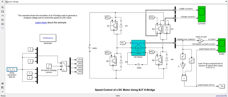
Along with the DC motor- and BJT H-Bridge setup, there is a separate circuit created for PWM employment. The gate pulses for the Switches are provided in a certain fashion such that the switching will happen like what is being told in the previous paragraph; the current will flow through those BJTs and Diodes accordingly. From the Pulse Generator block, we can find some preset values given in the settings. The block allows us to modify the duty cycle as per our needs and that is how we can adjust the dc motor current in a way that it never shoots up that much while changing its operation from forward to reverse motoring conditions.
The preset value of the duty cycle was 75%, which means that the voltage is supplied to the motor terminals for 75% of the time during a single cycle, and the remaining 25% of the time the dc motor does not receive any voltages from the source. The time between the alteration from ON ad OFF stages we can vary the total amount of voltage supplied to the motor and this way one can control the speed of a hybrid/electric vehicle.
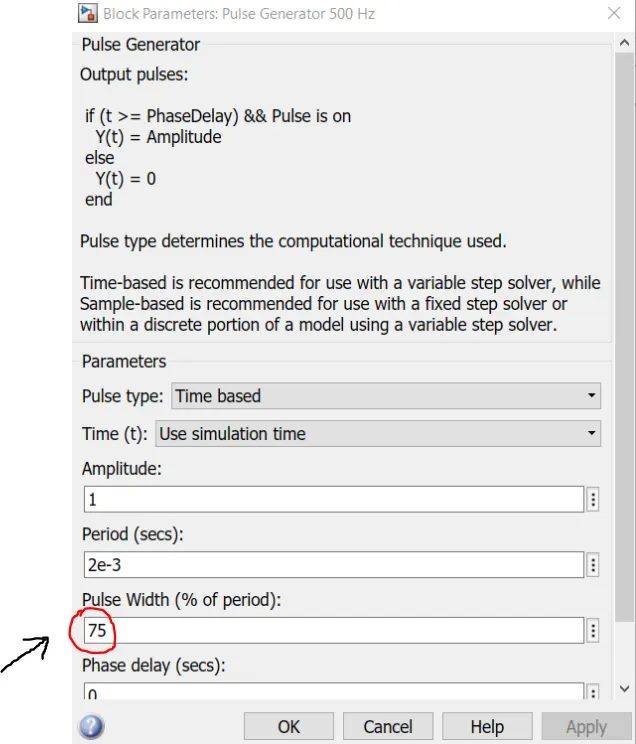 ----------> Pulse generator block and its duty cycle setting
Now, to adjust the duty cycle to a value where the dc motor current does not shoot up while reversing the direction of operation, the duty cycle value was cut down to 50% and 30%, and all the results were shown one after another so that one can compare the effect of duty cycle on the motor current behavior quite easily. For the theoretical explanation, it can be pointed out that the more the duty cycle is given in the PWM block, the more time the voltage will be applied to the dc motor terminals within a specific cycle and more will be the current overshoot will happen when the motor direction is reversed w.r.t. its previous one i.e. forward to reverse or reverse to forward direction. So, it is obvious that when the duty cycle is decreased in value, automatically the armature current will have lesser overshoots or rapid changes in values since the voltage is applied to the motor terminals for a lesser amount of time i.e less amount of voltage it gets over a complete cycle. The Outputs waveforms having duty cycle values 75%, 50%, and 30% are shown below.
The image below shows the output of the scope when the simulation is run using the preset values in the pulse generator block. There are 3 output graphs of angular speed, armature current, and the load torque all against a time axis.
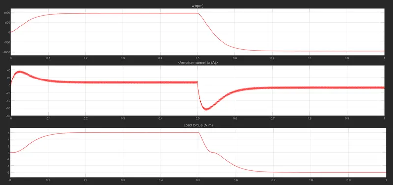 Duty Cycle 75%
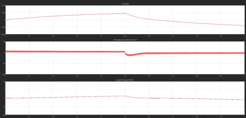 Duty Cycle 50%
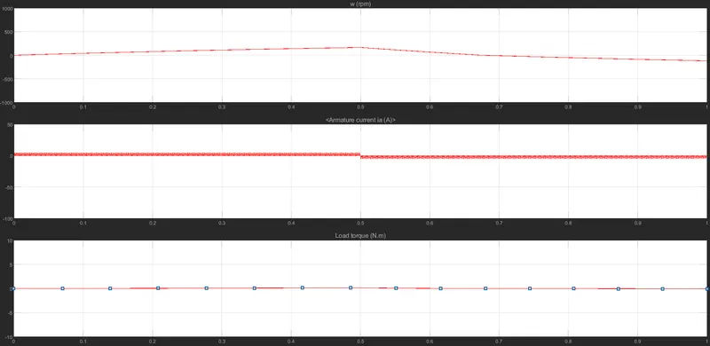
Duty Cycle 30%
From the output results, we can see that the armature current does not shoot anymore or don't have a rapid change in value from froward to reverse operating directions with a 30% duty cycle and as the duty cycle is decreased from 75% ----> 50% -----> 30%; the armature current shoot in transition occurs in a very less amount. The simple reason is that with the lesser duty cycle, the voltage is supplied to the dc motor terminals for a less amount of time, and hence the current value of the armature will be less, and since the change in armature current values will not be rapid that's why it did not shoot up.
Problem Statement- 2: Refer to help section of ‘The Four-Quadrant Chopper DC Drive (DC7) block’. Compare it with the H-bridge model.
Answer: The 'DC7' motor drive in SIMSCAPE, referred to as the four-quadrant chopper DC drive block in MATLAB/SIMULINK. It represents a four-quadrant, DC-supplied chopper drive for DC motors, featuring closed-loop speed control with the four-quadrant operation. This closed-loop speed control gives us the armature current of the machine as an output. By using a PI current controller and adjusting the chopper duty cycle, we get the commanded armature current as per our needs. The duty cycle is then compared with a sawtooth carrier signal to obtain the required PWM signals for the chopper.
Compared to other DC drives that are available, the main advantage of using the four-quadrant chopper DC drive is that it can operate in all 4 quadrants. Each quadrant in its characteristics represents a different mode of operation. The first quadrant is forward motoring, the second is reverse braking, the third is reverse motoring and the fourth is forward braking. Another advantage is that it comes with a high switching frequency DC-DC converters, resulting in a lower armature current ripple compared to thyristor-based DC drives. The Simulink block of DC7 and its circuit diagram is given below:
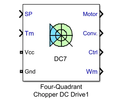
Simulink Block Circuit Diagram
From the help section of Matlab documentation, The DC7 file or the Four-Quadrant Chopper DC drive can be found out and by opening the model file we get the Simulink blocks like the following:
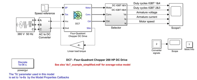
Four-quadrant chopper DC drives are used mainly due to their ability to work in all four quadrants of operation. It allows the controller to command the DC motor to rotate in clockwise and counterclockwise directions and also to perform braking. Traditional DC motors would rely on the innate friction and air resistance forces or actual physical brakes to bring the motor to rest. The other simpler option is to switch off the motor till it comes to rest and for using it in a car there will be mechanical and electrical breaks provided. The four-quadrant operation works like this:
- Forward Motoring: motor rotates clockwise; the controller applies a clockwise drive.
- Reverse Motoring: motor rotates anti-clockwise; the controller applies an anti-clockwise drive.
- Forward Braking: motor rotates clockwise; the controller applies an anti-clockwise drive.
- Reverse Braking: motor rotates anti-clockwise; the controller applies a clockwise drive.
Advantages:
- 4 quadrant choppers have more control over the deceleration of the motor and can more accurately brake the motor. This will make the deceleration smoother.
- The second benefit is that it reduces the risk of current spikes, which can damage the motor and the controller itself because this can occur when the motor is made to brake while running at a high speed. So the controller life is generally longer with 4 quadrant choppers, by mitigating those sudden surges or spikes from the output.
- A third advantage is that 4 quadrant choppers are more efficient because lesser energy is wasted as heat and lesser current spikes occur which means lesser power dissipation over a complete.
- In the case of a vehicle, the 4 quadrant chopper makes regenerative braking possible so that when the motor is made to brake, the kinetic energy of the rotor moving is transferred back as electrical energy which can then be used to charge a battery.
Comparison to H-Bridge Chopper Drive:
- Both BJT H-bridges and 4 quadrant choppers have their advantages and disadvantages. H-Bridges like the 4 quadrant choppers are also capable of the braking operation without using air resistance or friction or physical brakes to bring the motor to rest. 4 quadrant DC choppers are more commonly used in automobiles whereas BJT H-bridges are commonly used in robotics and electromechanical devices.
- Unlike 4 quadrant DC choppers, BJT H-bridges are not capable of performing regenerative braking but they can perform dynamic braking. It is this difference that makes 4 quadrant DC choppers a clear choice in hybrid and electric vehicles.
- In 4 quadrant DC choppers, the current signals are interrupted with one another to change the direction of rotation of the motor. This is done by a speed reference or a drive cycle from which the speed values are converted to current signals which interrupt one another to change the rotation of the direction of the motor. However, in BJT H-bridges, the polarity of the current is reversed (depending on the duty cycle) to change the direction of rotation of the motor.
- Also, the current signals in 4 quadrant DC choppers are chopped meaning that they are not continuous, they are discrete and so take less time for simulations. But in BJT H-bridges, the current values are not chopped, meaning that they are continuous and so take more time for simulations.
- As a matter of fact, In the four-quadrant DC choppers, a PI controller is used to control the speed and the current by comparing them with the reference values; but in the H-bridge, this is not implemented.
Problem Statement- 3: Make a suitable EV model using DC7 block and make a result report.
Answer: To shape the DC7 Simulink model and to make it an EV model, some adjustments had to be made.
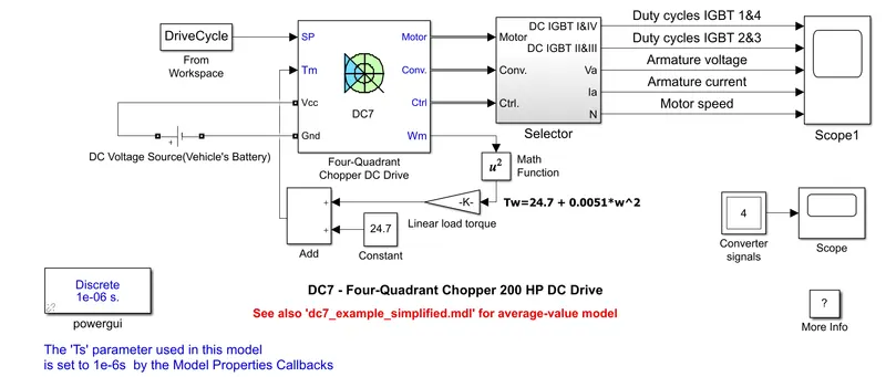
From the above block diagram, some modifications are clearly visible. Those are discussed separately in the following sections:
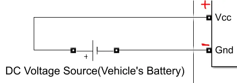
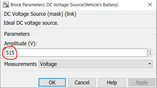
- Voltage Source: The AC voltage source is replaced with a DC voltage source to shape it into an EV model. The amount of DC voltage supplied is 515 volts; the positive terminal of this battery is connected to the VCC of the DC chopper drive and the negative terminal is connected to the ground.
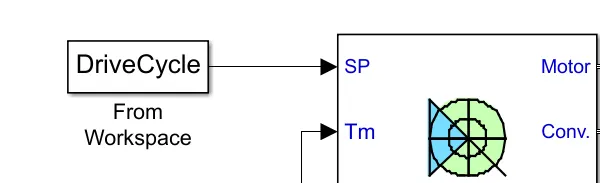
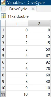
- Drive Cycle Input: The speed reference block was replaced by the drive-cycle data of an EV, which was created as a workspace variable and loaded from the same at the time of the simulation. The drive cycle is here given a small amount of data of 10 seconds only.
- Relation Between Tm and Wm: The relation is reestablished to make it an EV model-like set-up. Here, an equation from the previous challenge is used: Tm = 24.7 + (0.0051)*(Wm)^2, where Tm= Motor Torque and Wm= Motor Speed.
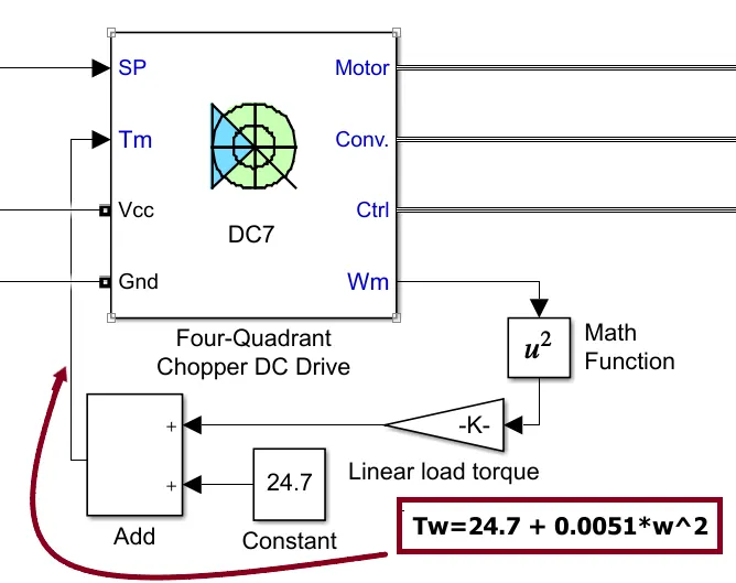
A constant block(given value 24.7), a math function block(to square the Wm value), and an add block (added the constant part with the other part) were used to perform this task. The gain block was also adjusted to introduce the value of 0.0051.
All the other blocks remain unchanged because all the needed adjustments are already made in the Simulink model and it is now representing an EV model.
Then, the 'stop time' of the simulation is set to 10 seconds because the drive cycle is also 10 seconds in duration. After this, the simulation is run and the output of the simulation is seen from the scope block connected to the selector block.
The screenshot of the scope output is shown below:
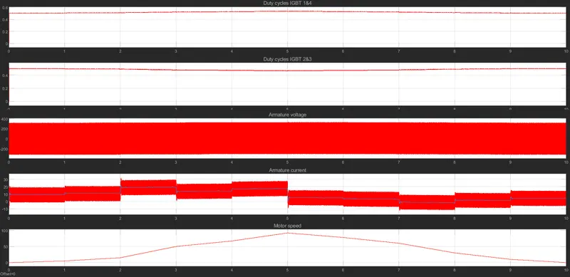
In the above output, the IGBT currents are not that clear and current variations are not clearly visible. The zoomed version of the same is given below to understand it easily:
 ----> Zoomed in to understand the switching
Result Report: We can see that the results of the different graphs are plotted against the time axis up to 10 seconds which matches the duration of the drive cycle which was inserted into the DC chopper drive block. The first two graphs show the duty cycles of the IGBT switches 1 & 4 and 2 & 3 and it is evident that these two graphs are mirror images of one another. The results of each of the scope outputs are explained below briefly.
IGBT 1 & 4 Duty Cycle
Initially, there is a spike in the duty of IGBT switches 1 & 4 because the system is adjusting itself to provide the correct voltage to operate the motor. Throughout the operation, the duty cycle is seen in pulses as it steadily increases to change the output voltage that is provided to the motor load. The duty cycle increases to reach a peak value of 0.540 at t = 5 seconds which is when the vehicle's speed is a maximum of 92 km/hr. After this, the duty cycle decreases as the motor angular speed decreases and eventually reaches the duty cycle level at which it started i.e. at-rest position. The increase and decrease in the duty cycle corresponding to the power requirement by the motor to achieve a particular angular speed. When the motor angular speed increases, the duty cycle will also increase so that the average voltage that is supplied to the motor will be more. When the motor angular speed decreases, the duty cycle will also decrease so that the average voltage that is supplied to the motor will be lesser.
IGBT 2 & 3 Duty Cycle
Similar to IGBT 1 & 4, there is initially a spike in the duty cycle as the system adjusts itself to provide the correct voltage to operate the motor. The duty cycle of IGBT switches 2 and 3 decreases in pulses as the motor angular speed increases. The decrease in this duty cycle corresponds to the increase in the duty cycle of IGBT 1&4. In other words, the first two graphs are mirror images of each other by form shape. The duty cycle reaches a minimum of 0.460 at t = 5 seconds when the vehicle's speed is at a maximum level of 92 Km/hr. From here, the duty cycle increases for the rest of the drive cycle as the motor speed decreases. The increase and decrease in the duty cycle corresponding to the power requirement by the motor to achieve a particular angular speed. When the motor angular speed increases, the duty cycle will also increase so that the average voltage that is supplied to the motor will be more. When the motor angular speed decreases, the duty cycle will also decrease so that the average voltage that is supplied to the motor will be lesser.
Armature Voltage
The armature voltage from the graph appears to be fluctuating between 320 V and - 320 V and this is occurring at a very high frequency. The armature voltage will fluctuate because every time the power switch occurs between IGBT 1 & 4 and 2 & 3; the polarity of the voltage will reverse as it flows through the armature of the inductor. When IGBT switches 1 & 4 are ON and switches 2 & 3 are OFF, the polarity of the armature voltage polarity will be positive. When IGBT switches 2 & 3 are ON and switches 1&4 are OFF, the armature voltage polarity will be negative. This fluctuation in polarity will continue throughout the drive cycle as the motor will operate in the forward motoring mode only since the motor is not being made to brake or rotate in the reverse direction.
Armature Current
Initially, there is a spike in the armature current when the motor starts to work. The armature current then stabilizes its fluctuation levels between approximately -10 A and 20 A within the initial fractions of seconds. Then, the armature current fluctuations occur very rapidly as the IGBT switches 1 & 4 get switched ON and OFF continuously at a very high frequency. This switching is done obviously to control the power that the motor receives to make it perform the forward motoring operation. The forward motoring operation occurs till t = 5 seconds which is when the motor angular speed is a maximum. After this, the motor angular speed decreases till the end of the drive cycle and this causes a change in the fluctuation of current. The maximum armature current and minimum armature current both decrease as the power requirement to the motor decrease when the motor angular speed decreases. The armature current follows the drive cycle data very well.
Motor Speed
This graph is simply plotting the motor angular speeds against the time and just translates the drive cycle data into a plot. The angular speed of the motor increases gradually from rest at t = 0 seconds to a maximum at t = 6 seconds, when the vehicle has a speed of 92 Km/hr. It is at this point, that the maximum power is required by the motor to achieve this angular speed. From here, the motor speed steadily decreases and eventually returns to the resting state by the end of the drive cycle at t = 10 seconds.
Problem Statement- 4: Explain the operation of the BLDC motor briefly.
Answer:
BLDC Motor: A brushless DC motor (also known as a BLDC motor) is an electronically commuted DC motor that does not have brushes. The controller provides pulses of current to the motor windings which control the speed and torque of the synchronous motor.
These types of motors are highly efficient in producing a large amount of torque over a vast speed range. In brushless motors, permanent magnets rotate around a fixed armature and overcome the problem of connecting current to the armature. Commutation with electronics has a large scope of capabilities and flexibility. They are known for smooth operation and holding torque when stationary. In conventional Brushed DC Motors, the brushes are used to transmit the power to the rotor as they turn in a fixed magnetic field. A BLDC motor used electronic commutation and thus eliminates the mechanically torn brushes.
Before explaining the working of a brushless DC motor, it is better to understand the function of a brushed motor. In brushed motors, there are permanent magnets on the outside and a spinning armature that contains an electromagnet is inside. These electromagnets create a magnetic field in the armature when the power is switched on and help to rotate the armature.
The brushes change the polarity of the pole to keep the rotation on of the armature. The basic working principle for the brushed DC motor and brushless DC motor is the same i.e. internal shaft position feedback.
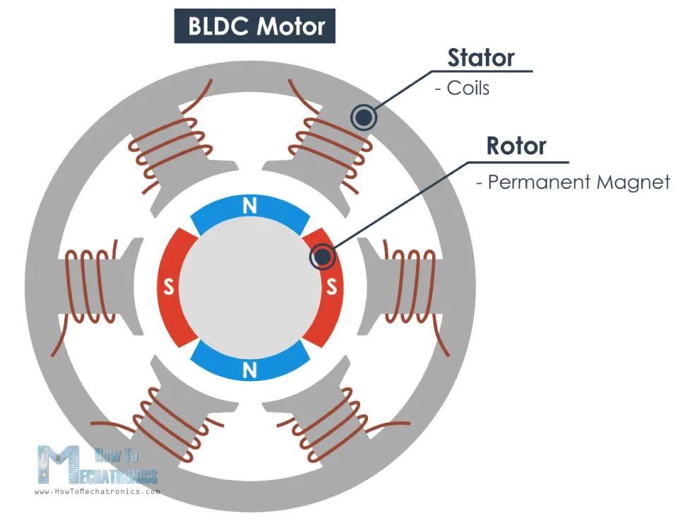
A Brushless DC motor has only two basic parts: the rotor and the stator. The rotor is the rotating part and has rotor magnets whereas the stator is the stationary part and contains stator windings. In BLDC permanent magnets are attached to the rotor and move the electromagnets to the stator. The high-power transistors are used to activate electromagnets for the shaft turns. The controller performs power distribution by using a solid-state circuit.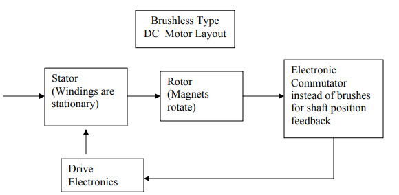
Construction of BLDC motors:
The main design difference between brushed and brushless motors is the replacement of a mechanical commutator with an electric switch circuit. Keeping that in mind, a BLDC motor is a type of synchronous motor in the sense that the magnetic field generated by the stator and the rotor revolve at the same frequency.
Brushless Motors are available in three configurations: single-phase, two-phase, and three-phase. Out of these, the three-phase BLDC is the most common one.
The following image shows the cross-section of a BLDC Motor.
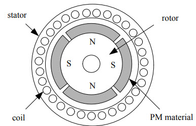
As you can see in the image, a BLDC motor consists of two main parts: a stator and a rotor.
Stator:
The structure of the stator of a BLDC motor is similar to that of an induction motor. It is made up of stacked steel laminations with axially cut slots for winding. The winding in BLDC is slightly different than that of the traditional induction motor.
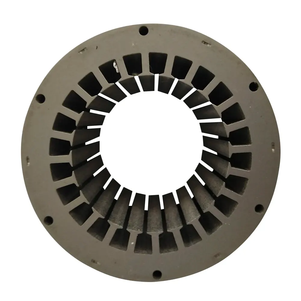
Generally, most BLDC motors consist of three stator windings that are connected in star or ‘Y’ fashion (without a neutral point). Additionally, based on the coil interconnections, the stator windings are further divided into Trapezoidal and Sinusoidal Motors.
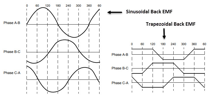
In a trapezoidal motor, both the drive current and the back EMF are in the shape of a trapezoid (sinusoidal shape in case of sinusoidal motors). Usually, 48 V (or less) rated motors are used in automotive and robotics (hybrid cars and robotic arms).
Rotor:
The rotor part of the BLDC Motor is made up of permanent magnets (usually, rare earth alloy magnets like Neodymium (Nd), Samarium Cobalt (SmCo), an alloy of Neodymium, Ferrite, and Boron (NdFeB)).
Based on the application, the number of poles can vary between two and eight with North (N) and South (S) poles placed alternately. The following image shows three different arrangements of the poles. In the first case, the magnets are placed on the outer periphery of the rotor.
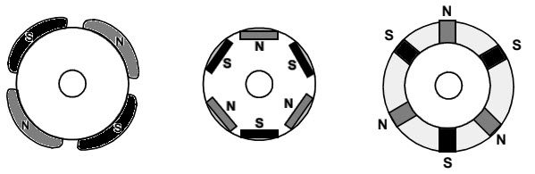
The second configuration is called a magnetic-embedded rotor, where rectangular permanent magnets are embedded into the core of the rotor. In the third case, the magnets are inserted into the iron core of the rotor.
Now, some crucial things are discussed which are a must to have in the case of BLDC motors i.e. its sensors.
The BLDC motor has no Brushes, the commutation is controlled electrically. To rotate the motor, the windings of the stator must be energized in a sequence, and the position of the rotor which the North poles and South poles of the rotor must be known to precisely energize a particular set of stator windings.
A Position Sensor, which is usually a Hall Sensor is generally used to detect the position of the rotor and transform it into an electrical signal.
HALL-EFFECT SENSOR:
A Hall-effect sensor (or simply Hall sensor) is a device to measure the magnitude of a magnetic field. Its output voltage is directly proportional to the Magnetic field strength through it. The Hall-sensor is used for, Proximity Sensing, Positioning Sensor, Speed Detection, and Current Sensing.
Most BLDC Motors use three Hall Sensors that are embedded into the stator to sense the rotor’s position. The output of the Hall Sensor will be either Low or High. Depending on whether the North or South pole of the rotor passes near it. By combining the results from the three sensors, the exact sequence of energizing can be determined.
THE WORKING PRINCIPLE OF BLDC MOTOR:
Consider the following setup of three windings in the stator designated A, B, and C. For the sake of understanding, let us replace the rotor with a single magnet.
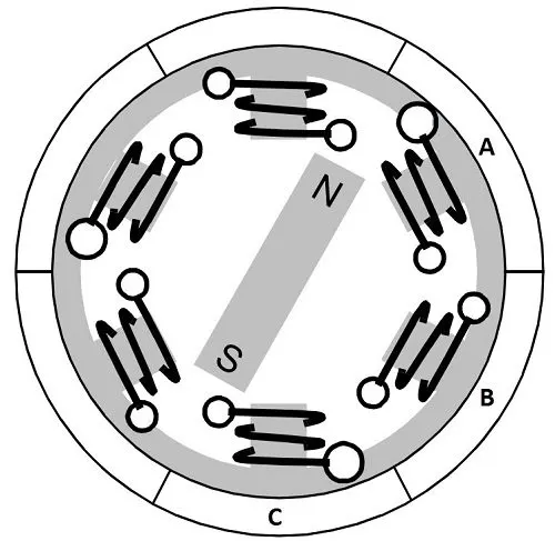
- We know that when a current is applied through a coil, a magnetic field is generated and the orientation of the field lines i.e. the poles of the generated magnet will depend on the direction of the current flowing through the coil.
- Now by supply current to coil A so that it will generate a magnetic field and attract the rotor magnet. The position of the rotor magnet will shift slightly clockwise and will align with coil A. similarly for coil B and coil C the magnet rotates in the clockwise direction
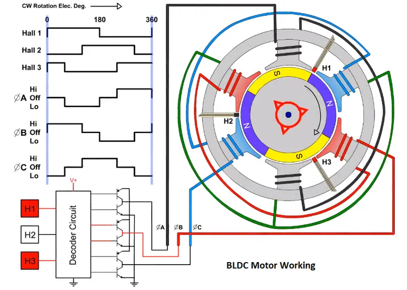
- Here, the Three-phase BLDC motor is used and the phases are A, B, &C.
- These phases are connected to an Electronically commutator which is a power electronic controller which acts as an Inverter.
- The Hall sensor is placed between poles to sense the position of the rotor.
- Here we have taken three Hall sensors and placed them in Stator.
- Each phase signal is combined with High, Low, and OFF.
- The hall signal is taken as the frequency of 0 to 360 degrees.
- When The Hall-1 is OFF to ON, Hall-2 is OFF, and Hall-3 is OFF to ON. So Hall-1 and Hall-3 are present.
- Then phase A is in the OFF signal, phase B is OFF to High, and phase C is Low.
- Similarly, in three phases if one phase is of the other two phases are acts as positive and negative.
To understand it more easily a gif of the same above circuit is given below:
Advantages of BLDC Motor:
- Brushless motors are more efficient as their velocity is determined by the frequency at which current is supplied, not the voltage.
- As brushes are absent, the mechanical energy loss due to friction is less which enhanced efficiency.
- BLDC motor can operate at high-speed under any condition.
- There is no sparking and much less noise during operation.
- More electromagnets could be used on the stator for more precise control.
- BLDC motors accelerate and decelerate easily as they are having low rotor inertia.
- It is a high-performance motor that provides large torque per cubic inch over a vast sped range.
- BLDC motors do not have brushes which make them more reliable, high life expectancies, and maintenance-free operation.
- There are no ionizing sparks from the commutator, and electromagnetic interference is also get reduced.
- Such motors cooled by conduction and no airflow are required for inside cooling.
Limitations of BLDC Motors:
- These motors are costly compared to brushed motors
- The need for additional sensors
- The electronic controller required to control this motor is expensive
- Complex Driver-Circuit is required
- The limited high power could be supplied to the BLDC motor, otherwise, too much heat weakens the magnets and the insulation of winding may get damaged.
Application of BLDC Motors:
- Electric vehicles, hybrid vehicles, and electric bicycles can be constructed
- Industrial robots, CNC machine tools, and simple belt-driven systems
- Fans, pumps, and blowers with a low noise-inducing environment.
Conclusions: All the problem statements are addressed successfully.
References:
- https://www.etechnog.com/2019/03/h-bridge-circuit-working-application-advantage.html
- Multi Quadrant Operation of DC Motor in Simulink: Skill-Lync (skill-lync.com)
- https://in.mathworks.com/help/physmod/sps/ug/speed-control-of-a-dc-motor-using-bjt-h-bridge.html
- DC7 - Four-Quadrant Chopper 200 HP DC Drive - MATLAB & Simulink (mathworks.com)
- https://www.electronicshub.org/brushless-dc-motor-bldc-motor/
- https://www.electrical4u.com/brushless-dc-motors/
- Brushless DC Motor, How it works? - YouTube
- BLDC Motor Construction - YouTube
- BLDC Motor control -Power electronics and Drives - Pantech Blog (pantechsolutions.net)