(2)Module 2: Week -2 --> To simulate a 'Doorbell' and an 'Electric Heater Set-up' using Simulink models
Week 2 Challenges: The challenges given in this week, are to present in a project format. Two separate challenges are described below:
Aim: To simulate(separately) an electric doorbell and heater set-up using Simulink models.
Objective:
1) Develop a Simulink model of a doorbell using a solenoid block and also to observe the plunger movements when the switch is being closed for every two seconds.
2) Use thermistor as a sensor of a heater, to turn it on and off as per the following conditions:
Temperature timeline: 0-10 seconds = 20-degree centigrade
10-30 seconds = 27-degree centigrade
30-50 seconds = 23-degree centigrade
Fan Operations: On only when the temperature is greater or equal to 25-degree centigrade.
Part 1 Solution:
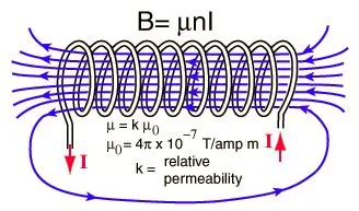
Theory: The core of a conventional doorbell is an electromagnet, which is basically a coil of wire wrapped around a piece of magnetic metal. When electrical current passes through wires it creates a small magnetic field around that wire. Greater the coiling greater the magnification of the magnetic field. The basic set-up for a doorbell is given below:
When we hold down or press a doorbell button, it closes its electrical circuit. Due to this, the threshold current flows through the electromagnet and the arms which strikes the bell(gong)is connected to spring at one end and an iron ball at the other end. The mechanical part which strikes is called a striker or hammer. It is attached to a metal strip, which the electromagnet attracts when the circuit is completed, because of the current flowing through it. The type of electromagnet used in here is a solenoid.
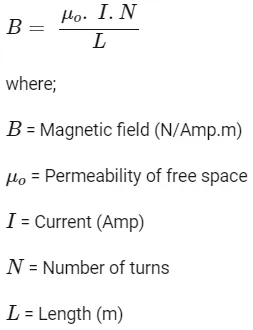
Solenoid generates a controlled magnetic field through a coil wound into a tightly packed helix. The coil can be arranged to produce a uniform magnetic field in a volume of space when an electric current passes through it. N is the number of loops the solenoid has which indicates that how many times the same wire been wrapped the cylinder. Higher the number of turns more strong the magnetic field is. The formula for the field inside the solenoid can be given by the following:
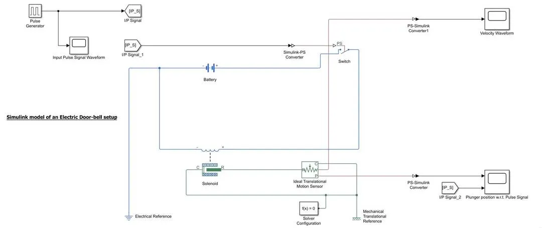
The Simulink model for the doorbell setup is given below:
Waveforms and Discussions:
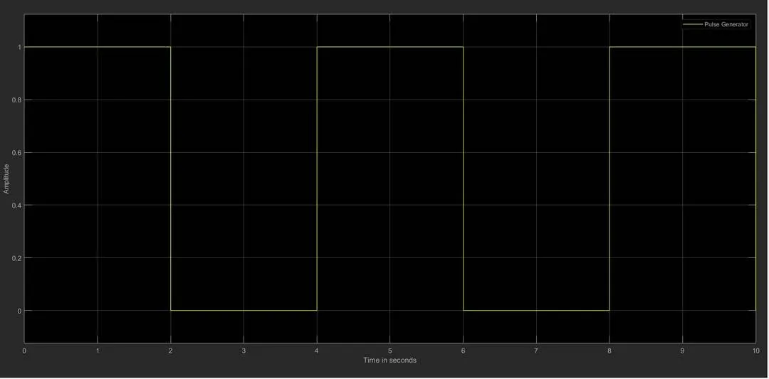
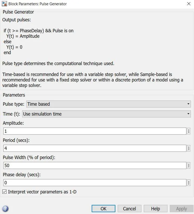
From the above, one can clearly see that a pulse input has been given to the switch block of the doorbell set up by creating a situation where the switch is closed for every 2 seconds and then released. To create such situations the needed parameter for the pulse generator is given below:
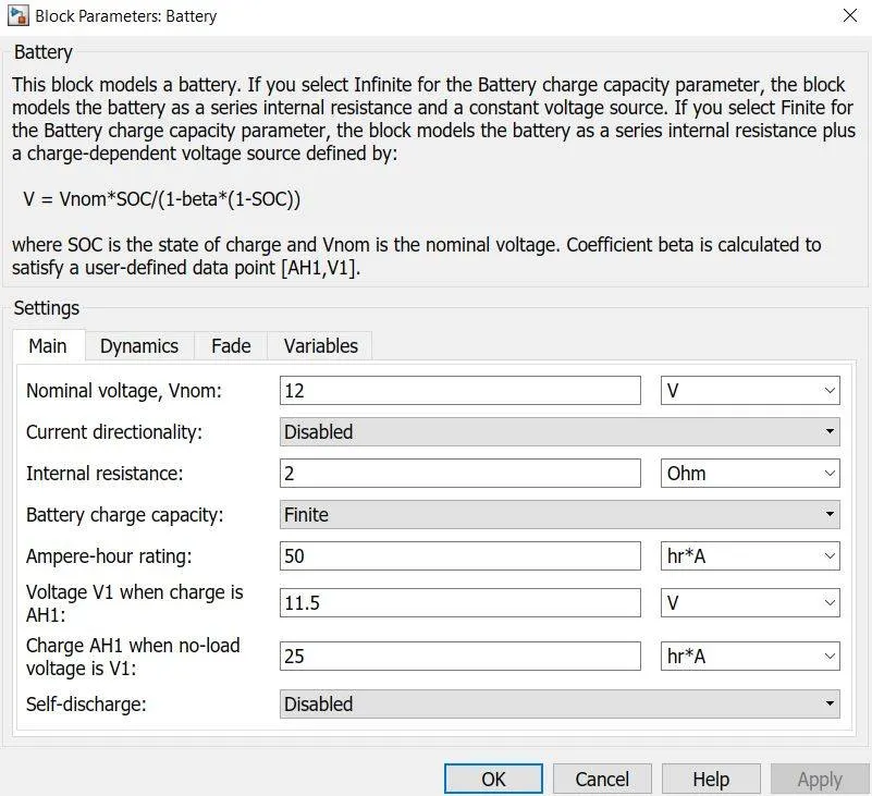
Also, the details of the parameters and values of the battery block and the solenoid block are shown respectively:
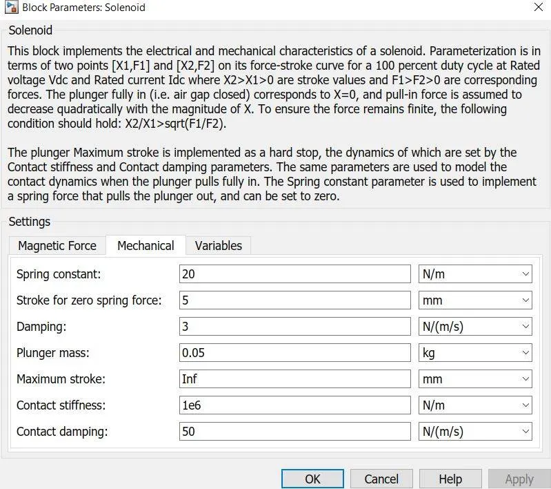
The plunger is represented by the ideal translational motion sensor block whose initial condition is set to 5m position.
Output 1:
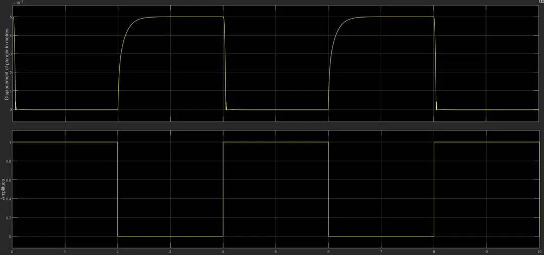
Here, the plunger position for the input pulse signal is being shown. From we can see at the output signal is showing the physical motion of the plunger where we receive a physical output signal from the translational emotional sensor and the signal is then converted to Simulink signal by PS-Simulink converter and then the signal is observed using a scope. The inward motion or movement of the plunger towards the solenoid is calculated as negative and if away from the solenoid, then it is considered as positive. It is clear from the graph when the switch is closed the plunger position goes away from the solenoid and when it is open, at that moment the plunger restored to its previous position. For different values of the damping, the nature of the restoring path will be slightly different.
Also, the velocity diagram for the plunger is given in the below output waveform:
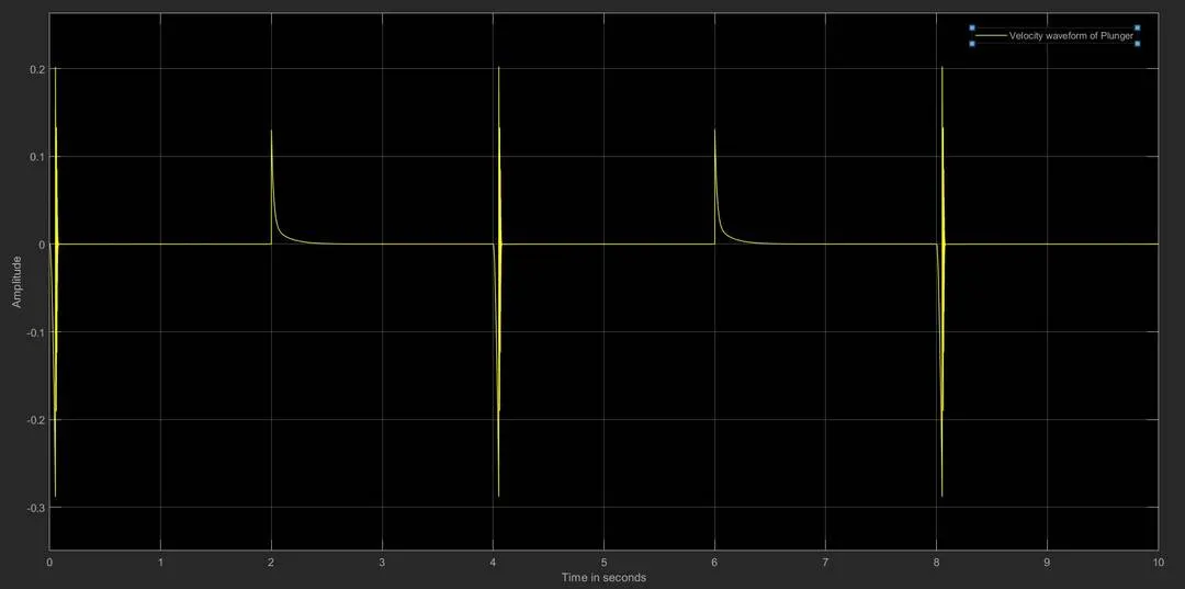
Here, it is clear from the results that for every two seconds when the switch is being close and the circuit is complete, at those moments due to presence of current through the solenoid the plunger is moved and the arm hit the gong; in this way, the doorbell is ranged.
Part 2 Solution:
Thermistor:
A thermistor is a different type of resistor whose resistance is highly dependent on the temperature conditions than the other resistors. They are widely used as inrush current limiters, temperature sensors(negative temperature coefficient or NTC type), self-regulating heating elements(positive temperature coefficient or PTC type typically)etc.
Now the type of thermistor used in this model is NTC type or the negative temperature coefficient type, which gives us the idea that with an increase of temperature the resistance is decreased in this case.
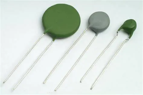 Here is a picture of thermistors which are used in practical implementations of different systems and circuits.
The Simulink Model of the thermistor based heater system is given below:
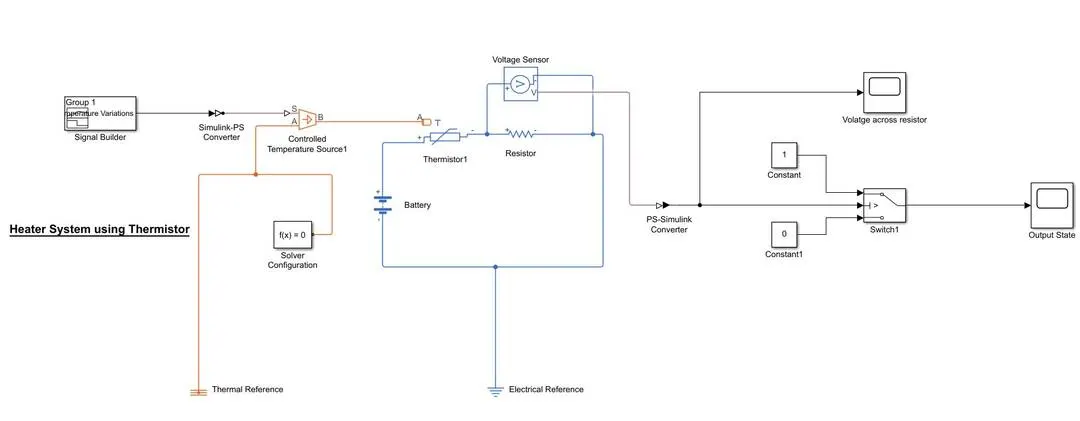
Here, a signal builder is used to generate the desired operating conditions at different temperatures.
Now, the main objective of the project is not to simulate an actual fan but to develop a certain logic or arrangement by which the operating conditions of the heater system with the fan can be achieved. The operating conditions are like the following:
Temperature timeline: 0-10 seconds = 20-degree centigrade
10-30 seconds = 27-degree centigrade
30-50 seconds = 23-degree centigrade
Fan Operations: On only when the temperature is greater or equal to 25-degree centigrade.
So, in this Simulink model, the main logic is provided where the fan system is assumed as a black box and being left apart for developing the most important part i.e. the logic itself. From the logical value at the scope named 'Output State', we can say that at that moment the fan will be On or Off. If the value shows 1 then the fan is On and if it is 0 then the fan is Off.
With the signal builder block, the desired temperature variations are given to the controlled temperature source block as an input.
Temperature Variations as Input:
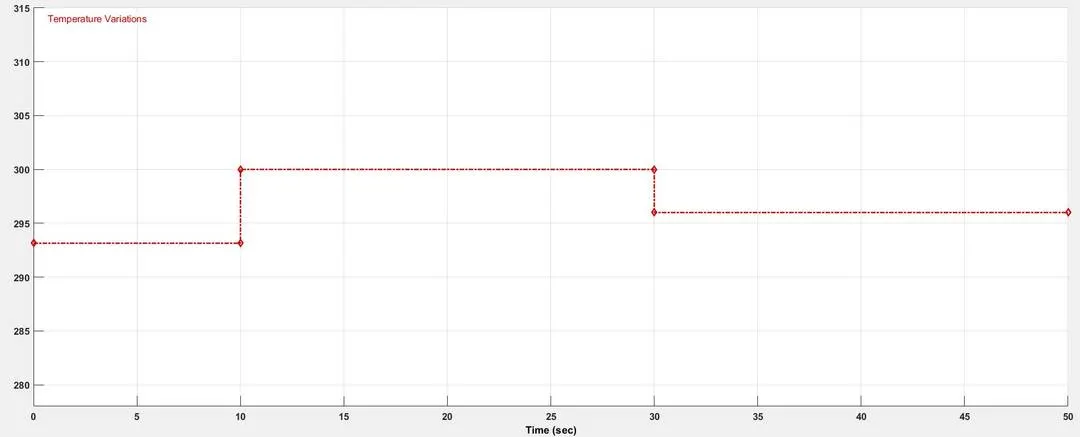
Here, the desired temperature variations are achieved. The temperature inputs are converted in kelvin because the controlled temperature source needs the inputs in kelvin as its default setup.
The needed electrical and thermal parameters of the thermistor are given below:
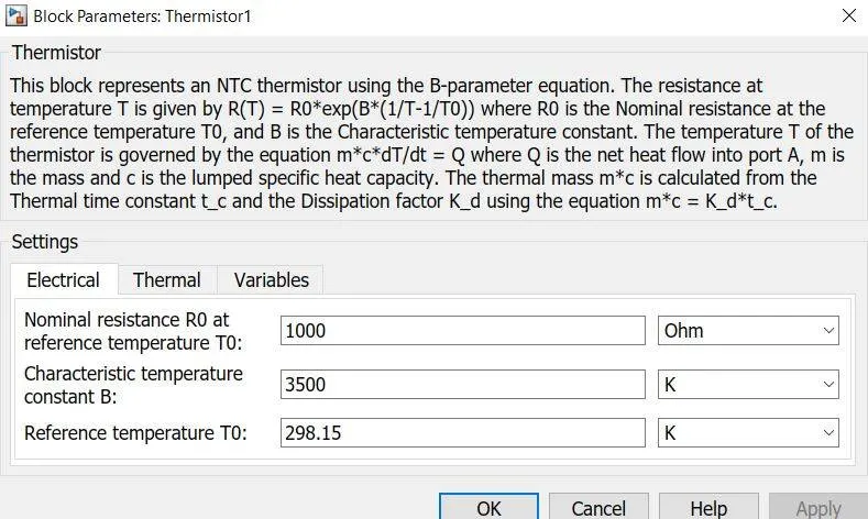
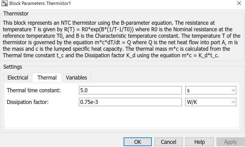
The Battery and resistor are connected in with the thermistor block. A voltage sensor was given across the resistor to measure the change in voltage during variable temperature conditions, given as inputs from the signal builder block. The value of the regular resistor can be chosen arbitrarily, but it should not be altered once the threshold value is observed. The Threshold temperature was given 25-degree Celsius and the corresponding voltage of the voltage sensor block was noted. The desired conditions are given at the output scope where high state or fan is ON only the temperature is above 25-degree centigrade at timeline 10 to 30 seconds.
Output 1- Voltage Sensor Waveform:
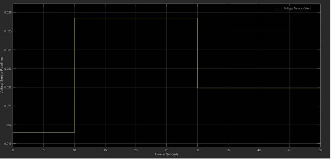
Here, it is evident that the voltage is higher between the time 10-30 seconds because it is the time when the temperature is reaching 300K, so the voltage drop across the resistor will also be high. The thermistor's main work here is to sense the temperature and then drive the fan system accordingly.
Output 2- Logic state value:
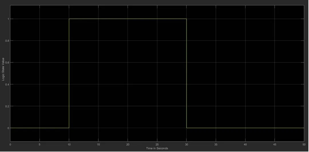
Here, the logic state value is observed. It is in High state or value 1 only between the time 10 to 30 seconds because it is the only time when the temperature is at 27-degree centigrade which is greater than the value 25-degree centigrade. Due to this logical set-up, the fan is 'On' only between this time when the temperature is above 25-degree centigrade and 'Off' for the rest of the time when the temperature is below that threshold value.
So we can say that our objectives are successfully achieved for both the problem statements.
The Simulink model of the two is given as google drive files:
https://drive.google.com/file/d/1IsvAjLW_CYaNi1b-ncpdrnaB33jkOSn4/view?usp=sharing
https://drive.google.com/file/d/1WPJ1uCk6ipgmmZXNsspNisnQdiwaOg-6/view?usp=sharing