(17) Module 2 : Final Project-1 ---> Powertrain for aircraft in runways
Project-1: Powertrain for aircraft in runways
Aim: Familiarization with "Powertrain Of Aircraft In Runways".
Objectives:
- Search and list out the total weight of various types of aircraft.
- Is there any difference between ground speed and airspeed?
- Why is it not recommended to use aircraft engine power to move it on the ground at the Airport?
- How an aircraft is pushed to the runway when it's ready to take off?
- Learn about take-off power, tyre design, rolling resistance, tyre pressure, brake forces when landing.
- With necessary assumptions, calculate the force and power required to push/pull an aircraft by a towing vehicle.
- Design an electric powertrain with a type of motor, its power rating, and energy requirement to fulfill aircraft towing application. Estimate the duty cycle range to control the aircraft speed from zero to highest. Make all required assumptions. Prepare a table of assumed parameters. Draw a block diagram of the powertrain.
Answers:
Objective No. (1):
Aircraft Authorized Gross Weight Limits (also referred to as certified weight limits) are laid down in the (AFM) or Associated Certificate of Airworthiness. The Authorized weight limits that can legally be used by an operator or airline are those listed in AFM and the weight and balance manual. The Authorized weight limits are chosen by the customer/ airline and they are referred to as “purchased weight”. The operator may purchase certified weight below the max. design weight because many of the operating fees are based on the aircraft AFM maximum allowable weight values. An aircraft purchase is typically a function of the certified weight purchased.
Maximum weights established for each aircraft, by design & certification must not be exceeded during aircraft operation (ramp or taxying, take-off, en-route flight, approach & landing) & during aircraft loading (zero fuel conditions, center of gravity positions, weight distribution) weights could be restricted on some type of aircraft depending on the aircraft handling requirements, e.g. Aerobatic Flight Aircraft, where certain Aerobatic Manoeuvres can only be executed with a limited gross weight.
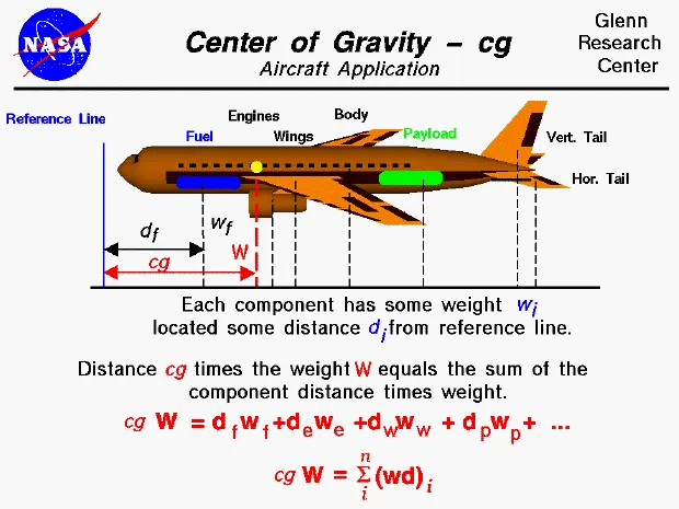
Also, the authorized maximum weight limits may be less as limited by the center of gravity, fuel density, and fuel loading limits. The different terms represent different weights or masses. For each flight, the weights are taken into account for several reasons like design, authorization, suitable condition, etc. A brief description of these is below:
Manufacturer's Empty Weight(MEW):
Also called Manufacturer's Weight Empty (MWE) or Licensed Empty Weight. It is the weight of the aircraft "as-built" and includes the weight of the structure, power plant, furnishings, installations, systems, and other equipment that are considered an integral part of an aircraft. This excludes any baggage, passengers, or usable fuel.
Zero-fuel weight(ZFW):
This is the total weight of the airplane and all its contents (including unusable fuel), but excluding the total weight of the usable fuel on board.
As a flight progresses and fuel is consumed, the total weight of the airplane reduces, but the ZFW remains constant.
Maximum zero fuel weight (MZFW) is the maximum weight allowed before usable fuel and other specified usable agents (engine injection fluid, and other consumable propulsion agents) are loaded.
Operating empty weight(OEW): (Roughly equivalent to basic empty weight on light aircraft)
It is the basic weight of an aircraft including the crew, all fluids necessary for operation such as engine oil, engine coolant, water, unusable fuel, and all operator items and equipment required for flight but excluding usable fuel and the payload.
Now, it is important to mention that the carrying capacity of an aircraft is known as the Payload. It includes cargo, people, extra fuel. In the case of a commercial airliner, it may refer only to revenue-generating cargo or paying passengers.
Maximum takeoff weight(MTOW):
This is the maximum weight at which the pilot of the aircraft is allowed to attempt to take off.
Regulated takeoff weight(RTOW):
Depending on different factors (e.g. flap setting, altitude, air temperature, length of runway), RTOW or maximum permissible takeoff weight varies for each takeoff. It can never be higher than MTOW.
The following image depicts takeoff weight components for a better idea.
Maximum landing weight(MLW):
This maximum weight at which an aircraft is permitted to land. The maximum certificated design weight at which the aircraft meets the appropriate landing certification requirements. It generally depends on the landing gear strength or the landing impact loads on certain parts of the wing structure. The MLW must not exceed the MTOW.
The maximum landing weight is typically designed for 10 feet per second (600 feet per minute) sink rate at touch down with no structural damage.
Maximum ramp weight(MRW):
Also called maximum taxi weight (MTW). It is the maximum weight authorized for maneuvering (taxiing or towing) an aircraft on the ground.
It is the total aircraft weight at any moment during the flight or ground operation. This decreases during the flight due to fuel and oil consumption.
To have a practical idea a complete listing of the "Aircraft's maximum takeoff weight(MTOW)" is given below with all the needed details:
Airplanes:
MTOW = Maximum take-off weight, MLW = Maximum landing weight, TOR = Take-off run (SL, ISA+15°, MTOW), LR = Landing run (SL, ISA+15°, MLW)
| Type | MTOW [kg] | MLW [tonnes] | TOR [m] | LR [m] | ICAO category | FAA category |
|---|---|---|---|---|---|---|
| Antonov An-225 | 640,000 | 591.7 | 3500 | Heavy | Super | |
| Scaled Composites Model 351 Stratolaunch | 589,670 | 3660 | Heavy | Super | ||
| Airbus A380-800[1][2][3] | 575,000 | 394 | 3100 | 1930 | Super | Super |
| Boeing 747-8F | 447,700 | 346.091 | 3100 | 1800 | Heavy | Heavy |
| Boeing 747-8 | 443,613 | 306.175 | 3100 | Heavy | Heavy | |
| Boeing 747-400ER | 412,770 | 295.742 | 3090 | Heavy | Heavy | |
| Antonov An-124-100M | 405,060 | 330 | 2520 | 900 | Heavy | Heavy |
| Boeing 747-400 | 396,900 | 295.742 | 3018 | 2179 | Heavy | Heavy |
| Lockheed C-5 Galaxy[4][5][6] | 381,000 | 288.417 | 2530 | 1494 | Heavy | Heavy |
| Boeing 747-200[7] | 377,840 | 285.700 | 3338 | 2109 | Heavy | Heavy |
| Boeing 747-300[7] | 377,840 | 260.320 | 3222 | 1905 | Heavy | Heavy |
| Airbus A340-500[8] | 371,950 | 240 | 3050 | 2010 | Heavy | Heavy |
| Airbus A340-600[8] | 367,400 | 256 | 3100 | 2100 | Heavy | Heavy |
| Boeing 777F | 347,800 | 260.816 | 2830 | Heavy | Heavy | |
| Airbus A330-900 | 352,000 | 251.5 | 3100 | Heavy | Heavy | |
| Boeing 777-300ER | 351,800 | 251.29 | 3100 | Heavy | Heavy | |
| Boeing 777-200LR | 347,450 | 223.168 | 3000 | Heavy | Heavy | |
| Boeing 747-100[7] | 340,200 | 265.300 | Heavy | Heavy | ||
| Airbus A350-1000 | 308,000 | 233.5 | Heavy | Heavy | ||
| Boeing 777-300 | 299,370 | 237.683 | 3380 | Heavy | Heavy | |
| Boeing 777-200ER | 297,550 | 213.00 | 3380 | 1550 | Heavy | Heavy |
| Airbus A340-300[8][9] | 276,700 | 190 | 3000 | 1926 | Heavy | Heavy |
| McDonnell Douglas MD-11 | 273,300 | 185 | 2990 | 1890 | Heavy | Heavy |
| Airbus A350-900 | 270,000 | 175 | 2670 | 1860 | Heavy | Heavy |
| Ilyushin Il-96M | 270,000 | 195.04 | 3115 | 2118 | Heavy | Heavy |
| McDonnell Douglas DC-10 | 256,280 | 183 | 2990 | 1890 | Heavy | Heavy |
| Boeing 787-9[10] | 254,000 | 192.777 | 2900 | Heavy | Heavy | |
| Boeing 787-10[10] | 254,000 | 201.849 | Heavy | Heavy | ||
| Airbus A340-200[8][11] | 253,500 | 181 | 2990 | Heavy | Heavy | |
| Ilyushin IL-96-300 | 250,000 | 175 | 2600 | 1980 | Heavy | Heavy |
| Airbus A330-300[12][13] | 242,000 | 185 | 2500 | 1750 | Heavy | Heavy |
| Airbus A330-200[12][13] | 242,000 | 180 | 2220 | 1750 | Heavy | Heavy |
| Lockheed L-1011-500 | 231,300 | 166.92 | 2636 | Heavy | Heavy | |
| Boeing 787-8[10] | 228,000 | 172.365 | 3300 | 1695 | Heavy | Heavy |
| Lockheed L-1011-200 | 211,400 | Heavy | Heavy | |||
| Ilyushin IL-86 | 208,000 | 175 | Heavy | Heavy | ||
| Boeing 767-400ER | 204,000 | 158.758 | 3414 | Heavy | Heavy | |
| Airbus A300-600R[14] | 192,000 | 140 | 2385 | 1555 | Heavy | Heavy |
| Boeing 767-300ER | 187,000 | 136.08 | 2713 | 1676 | Heavy | Heavy |
| Concorde | 185,000 | 111.1 | 3440 | 2220 | Heavy | Heavy |
| Airbus A300-600[14] | 163,000 | 138 | 2324 | 1536 | Heavy | Heavy |
| Boeing 767-300 | 159,000 | 136.078 | 2713 | 1676 | Heavy | Heavy |
| Airbus A310-300[14] | 157,000 | 124 | 2290 | 1490 | Heavy | Heavy |
| Vickers VC10 | 152,000 | 151.9 | Heavy | Heavy | ||
| Boeing 707-320B[15] | 151,000 | 97.5 | Heavy | Heavy | ||
| Boeing 707-320C[15] | 151,000 | 112.1 | Heavy | Heavy | ||
| Douglas DC-8-61 | 147,000 | Heavy | Heavy | |||
| Airbus A310-200[14] | 142,000 | 123 | 1860 | 1480 | Heavy | Heavy |
| Airbus A400M | 141,000 | 122 | 980 | 770 | Heavy | Heavy |
| Douglas DC-8-32 | 140,000 | Heavy | Heavy | |||
| Douglas DC-8-51 | 125,000 | Medium | Large | |||
| Boeing 757-300 | 124,000 | 101.6 | 2550 | 1750 | Medium | Large |
| Boeing 707-120B[15] | 117,000 | 86.3 | Medium | Large | ||
| Boeing 757-200 | 116,000 | 89.9 | 2347 | 1555 | Medium | Large |
| Boeing 720B[16] | 106,000 | 79.5 | Medium | Large | ||
| Boeing 720[16] | 104,000 | 79.5 | Medium | Large | ||
| Tupolev Tu-154M | 104,000 | 80 | Medium | Large | ||
| Tupolev Tu-204SM | 104,000 | 87.5 | 2250 | Medium | Large | |
| Convair 880 | 87,500 | Medium | Large | |||
| Boeing 737-900 | 85,000 | 66.36 | 2500 | 1704 | Medium | Large |
| Boeing 737-900ER | 85,000 | 71.35 | 2804 | 1829 | Medium | Large |
| Boeing 727-200 Advanced[17] | 84,000 | 70.1 | Medium | Large | ||
| Airbus A321-100[18] | 83,000 | 77.8 | 2200 | 1540 | Medium | Large |
| Boeing 737-800 | 79,000 | 65.32 | 2308 | 1634 | Medium | Large |
| Boeing 727-200[17] | 78,000 | 68.1 | Medium | Large | ||
| McDonnell-Douglas MD-83 | 73,000 | 63.28 | Medium | Large | ||
| Boeing 727-100[17] | 72,500 | 62.4 | Medium | Large | ||
| Boeing 727-100C[17] | 72,500 | 62.4 | Medium | Large | ||
| McDonnell-Douglas MD-90-30 | 71,000 | 64.41 | 2165 | 1520 | Medium | Large |
| de Havilland Comet 4 | 70,700 | Medium | Large | |||
| Boeing 737-700 | 70,000 | 58.06 | 1921 | 1415 | Medium | Large |
| Airbus A320-100[18] | 68,000 | 66 | 1955 | 1490 | Medium | Large |
| Boeing 737-400 | 68,000 | 54.9 | 2540 | 1540 | Medium | Large |
| de Havilland Comet 3 | 68,000 | Medium | Large | |||
| Boeing 377 | 67,000 | Medium | Large | |||
| Boeing 737-600 | 66,000 | 54.66 | 1796 | 1340 | Medium | Large |
| Airbus A220-300 | 65,000 | 57.61 | 1890 | 1494 | Medium | Large |
| Hawker Siddeley Trident 2E | 65,000 | Medium | Large | |||
| Airbus A319[18] | 64,000 | 62.5 | 1850 | 1470 | Medium | Large |
| Boeing 737-300 | 63,000 | 51.7 | 1939 | 1396 | Medium | Large |
| Boeing 737-500 | 60,000 | 49.9 | 1832 | 1360 | Medium | Large |
| Airbus A220-100 | 59,000 | 50.80 | 1463 | 1356 | Medium | Large |
| Airbus A318[18] | 59,000 | 57.5 | 1375 | 1340 | Medium | Large |
| Boeing 717-200HGW | 55,000 | 47.174 | 1950 | Medium | Large | |
| Douglas DC-7 | 55,000 | Medium | Large | |||
| de Havilland Comet 2 | 54,000 | Medium | Large | |||
| Boeing 717-200BGW | 50,000 | 46.265 | 1950 | Medium | Large | |
| de Havilland Comet 1 | 50,000 | Medium | Large | |||
| Douglas DC-6A | 48,600 | Medium | Large | |||
| Douglas DC-6B | 48,500 | Medium | Large | |||
| Embraer 190[19] | 48,000 | 43 | 2056 | 1323 | Medium | Large |
| Caravelle III | 46,000 | Medium | Large | |||
| Fokker 100 | 46,000 | 39.95 | 1621 | 1350 | Medium | Large |
| Douglas DC-6 | 44,000 | Medium | Large | |||
| Avro RJ-85 | 42,000 | 36.74 | Medium | Large | ||
| Handley Page Hermes | 39,000 | Medium | Large | |||
| Embraer 175[20] | 37,500 | 32.8 | 2244 | 1304 | Medium | Large |
| Bombardier CRJ900[21] | 36,500 | 33.345 | 1778 | 1596 | Medium | Large |
| Embraer 170[22] | 36,000 | 32.8 | 1644 | 1274 | Medium | Large |
| Bombardier CRJ700 | 33,000 | 30.39 | 1564 | 1478 | Medium | Large |
| Douglas DC-4 | 33,000 | Medium | Large | |||
| Vickers Viscount 800 | 30,400 | Medium | Large | |||
| Bombardier Q400 | 28,000 | 28.01 | 1219 | 1295 | Medium | Large |
| Bombardier CRJ200 | 23,000 | 21.319 | 1918 | 1479 | Medium | Large |
| ATR 72-600 | 22,800 | 22.35 | 1333 | 914 | Medium | Large |
| Saab 2000 | 22,800 | 21.5 | 1300 | Medium | Large | |
| Embraer ERJ 145 | 22,000 | 19.3 | 2270 | 1380 | Medium | Large |
| ATR 42-500 | 18,600 | 18.3 | 1165 | 1126 | Medium | Small |
| Saab 340 | 13,150 | 12.930 | 1300 | 1030 | Medium | Small |
| Embraer 120 Brasilia | 11,500 | 11.25 | 1560 | 1380 | Medium | Small |
| BAe Jetstream 41 | 10,890 | 10.570 | 1493 | 826 | Medium | Small |
| Learjet 75[23] | 9,752 | 8.709 | 1353 | 811 | Medium | Small |
| Pilatus PC-24[24] | 8,300 | 7.665 | 893 | 724 | Medium | Small |
| Embraer Phenom 300[25] | 8,150 | 7.65 | 956 | 677 | Medium | Small |
| Beechcraft 1900D | 7,765 | 7.605 | 1036 | 853 | Medium | Small |
| Cessna Citation CJ4[26] | 7,761 | 7.103 | 1039 | 896 | Medium | Small |
| de Havilland Hercules | 7,000 | Medium | Small | |||
| Embraer Phenom 100 | 4,800 | 4.43 | 975 | 741 | Light | Small |
Objective No. (2):
Air-speed & Ground-speed of an Aircraft:
As mentioned above, true airspeed is simply the speed at which an aircraft is moving relative to the air it is flying in. As such, it’s also the speed at which the air is flowing around the aircraft’s wings.`Ground speed, on the other hand, is the aircraft’s speed relative to the ground. One thing that should be noted here is that it is horizontal rather than vertical speed – an aircraft climbing completely vertically would have a ground speed of zero. In other words, while airspeed is what determines whether there is enough airflow around an aircraft to make it fly, ground speed is what determines how fast an aircraft will get to its destination.
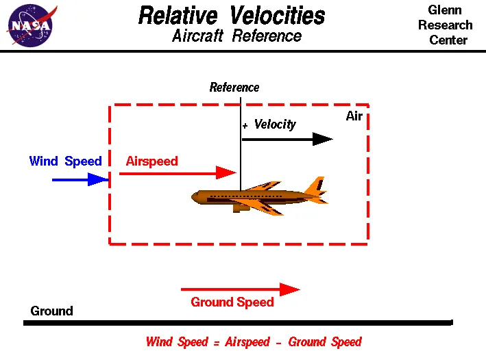
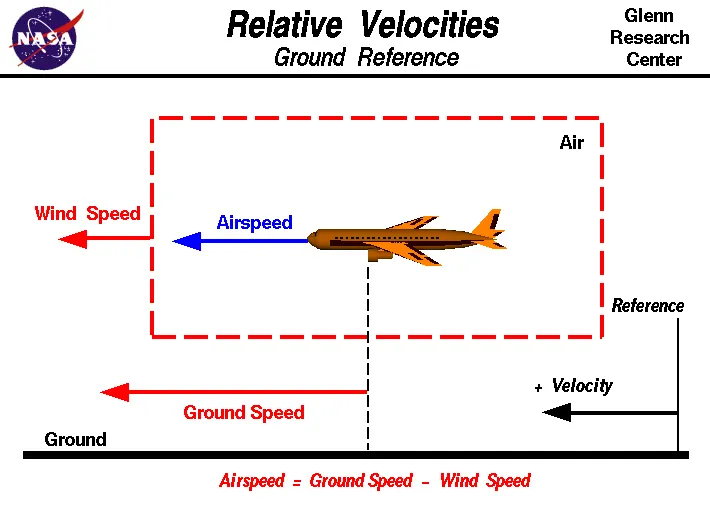
- The aircraft usually operates on land as well as in air and so we need to study their speed differences in-ground and in air
- The ground speed and the airspeed usually change based on the wind component.
- If we consider that there is no wind component then, ground speed = airspeed
- If the wind is blowing in the tail direction of the aircraft then, (airspeed > ground speed) so, airspeed = ground speed + wind component.
- If the wind is blowing in the head direction of the aircraft then, (airspeed < ground speed)so, airspeed = ground speed – wind component.
- Also, gravity plays a major role in increasing the aircraft's speed while it is descending.
-
Here wind speed is the vector difference between ground and airspeed. On a particular day, the wind speed may be zero and it is equal to the ground speed.
-
If the measured airspeed is greater than the observed ground speed the wind speed becomes positive.
Objective No. (3):
We are assuming passenger commuter aircraft and large airliners. Aircraft move using their own engine power all the time on the airport apron and taxiways under their own power to go towards runways and after landing taxi to their assigned gate.
The only time they use external assistance is to push back from the gate. It is not recommended to use aircraft engine power to move it on the ground at the airport because there are certain extreme cautions for everything around us are there. Large turbofan aircraft need help to reverse via a pushback tractor. The engines are turned on after the pushback is complete and the aircraft can move forward under Its own power.
To be accurate, some aircraft can reverse using a variable pitch prop or thrust reversing on turbofans but generally reversing is done via pushback tractors. Blasting jet reversers blows debris In the crowded gate area creating foreign object damage hazards for adjacent aircraft, gate equipment, or terminal waiting area glass windows.
Generally, most of the airplane can move in a reverse manner by making use of reverse thrust technology. But in most of the practice, it is not possible because when airplanes start using reverse thrust it will consume a lot of fuels as well as causes a lot of noise and also hazardous for the people working nearby.
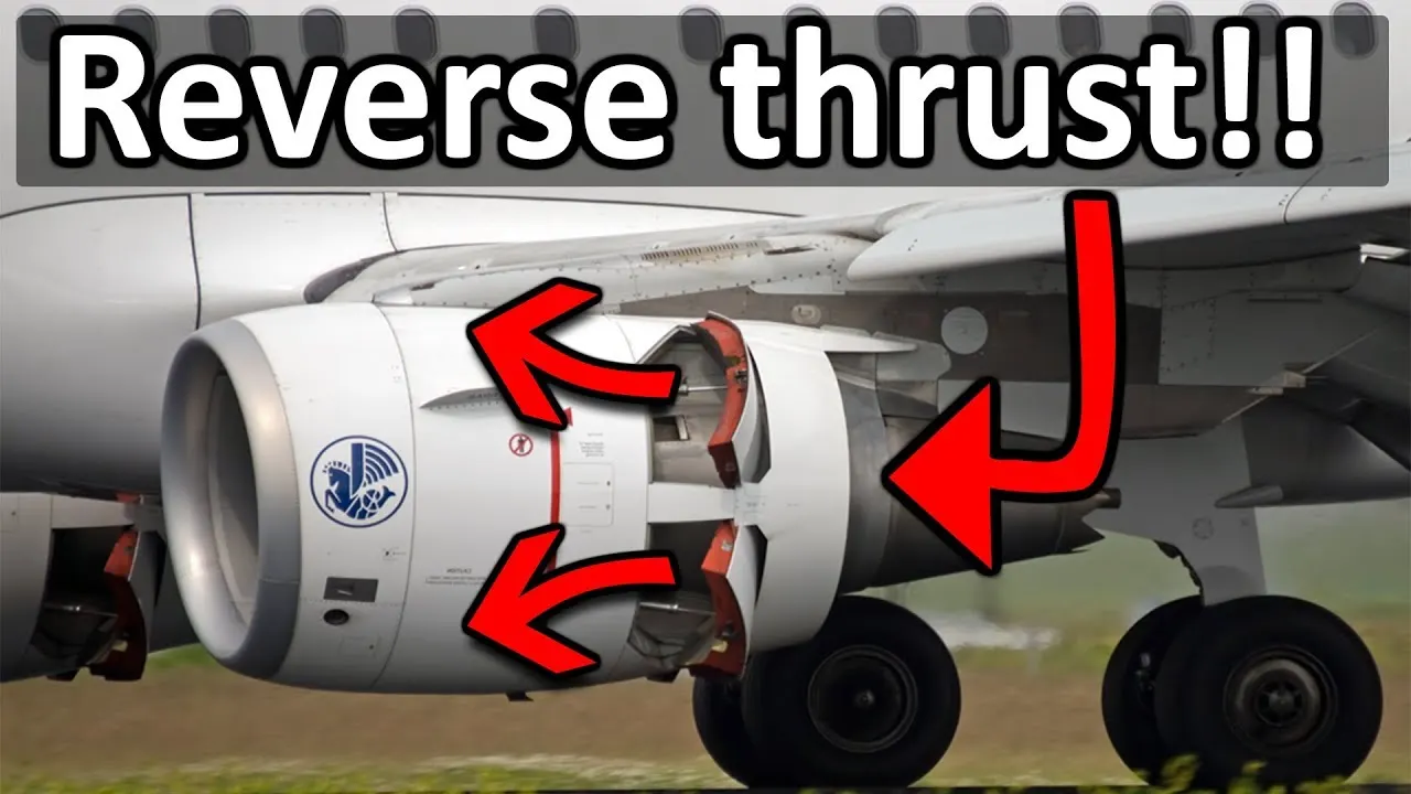
Applying thrust (gas) can create a blast behind each engine. People, equipment, and anything else in the way can be injured or damaged from the jet blast. Before we apply power to engines the areas in front of each engine are like other supercritical factors that must be carefully negotiated.
Another for not using reverse thrust is that the jet blast can cause damage to terminal buildings or their equipment; it also can affect the crew and passengers on that aircraft. Since the engine is also close to the ground it will blow off the sand and debris forward and sucks it to the engine and causes damage to it.
The immediate area in front of the jet engine creates an area where people and equipment can be sucked into the engine if anything is too close to the intake.
To avoid extreme cautions, it’s not recommended to use aircraft engine power to move it on the ground at the airport.
Objective No. (4):
Taxiing refers to the movement of an aircraft on the ground, under its own power. The aircraft moves on wheels. An airplane uses taxiways to taxi from one place on an airport to another; for example, when moving from a terminal to the runway.
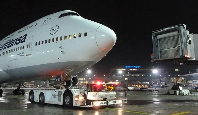
When the aircraft is ready with all the passengers and luggage the aviation, pushback is an Airport procedure during which an aircraft is pushed backward away from an airport gate by an external power. The aircraft always moves on the ground following the yellow lines, to avoid any collision with the surrounding buildings, vehicles, or other aircraft. The taxiing motion has a speed limit. Before making a turn, the pilot reduces the speed further to prevent tire skids. Just like cars, there is a certain list of priorities during taxiing. The aircraft that are landing or taking off have higher priority. The other aircraft have to wait for these aircraft before they start or continue taxiing. The thrust to propel the aircraft forward comes from its propellers or jet engines. Steering is achieved by turning a nose wheel or tail wheel/rudder; the pilot controlling the direction traveled with their feet. The use of engine thrust near terminals is restricted due to the possibility of jet blast damage. This is why the aircraft is pushed back from the buildings by a vehicle before they can start their own engines for taxiing.
- Pushbacks are carried out by special, low-profile vehicles called pushback tractors or tugs.
- These are heavy weighing low profile vehicles with enormous torque to do the job of pushing/pulling the large aircraft from the terminals to the runway.
- The Tractors are designed with extra weight purposely to offer them enough Traction to push/pull heavy aircraft.
Objective No. (5):
(i) Take off the power:
- Takeoff is the phase of flight in which an aerospace vehicle leaves the ground and becomes airborne.
- For aircraft that take off horizontally, this usually involves starting with a transition from moving along the ground on a runway
- The takeoff speed required varies with air density, aircraft gross weight, and aircraft configuration
- The power from the engine of the aircraft used to achieve the flight is called take-off power
- For light aircraft, usually, full power is used during takeoff.
- Large transport category (airliner) aircraft may use a reduced power for takeoff, where less than full power is applied to prolong engine life, reduce maintenance costs and reduce noise emissions.
(ii) Tyre Design:
The aircraft tyre is usually specially designed as the tyre has to withstand more load and also the higher speed at the same time. The number of tires required for any aircraft increases with the aircraft's weight, as the weight of the aircraft needs to be distributed more evenly. Aircraft's tread patterns are designed to facilitate stability in high crosswind conditions, to channel water away to prevent hydroplaning, and for braking effect. some of the tyre design is listed below.
Bias Ply Tyre:
- The bias ply tyre consists of casing plies running diagonally at approximately right angles to one another.
- The number of plies and the angles at which they are laid dictate strength and load capacity.
- High-performance bias aircraft tyres feature inter-tread reinforcing fabric (ITF). This provides additional high-speed stability, reduces tread distortion under load, protects the casing plies from damage, and can act as wear indicators on retread able tyres.
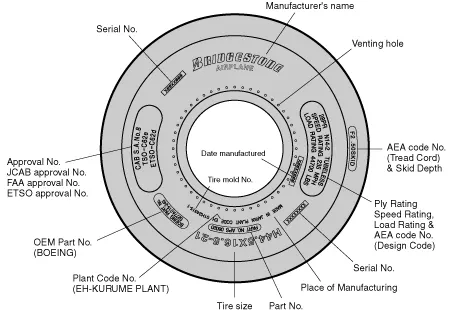
Tire Terminology
- Apex strip: A triangular piece of stiff rubber which is fitted onto the bead core to taper the rigid bead into the flexible body plies in the sidewall.
- Bead heel: Outer edge of the bead.
- Bead toe: Inner edge of the bead.
- Breaker: Breakers are fabric plies placed directly on the upper-most ply beneath the tread rubber. They disperse stress throughout the tire. This breaker is utilized in a limited number of Bridgestone aircraft tires.
- Chafer strip: Reinforces the beads and protects the cord body-plies from damage from rim friction or damage when replacing the rim.
- Carcass plies: Each nylon ply is held by wire beads across the tire to keep the tensile strength at the proper level, and is folded to the side of the sidewall. Each ply is provided with cushion rubber to reduce the shearing force produced between the cords of the tire when it is deformed. Multiple coated nylon cords are crossed alternately on the bias to make the carcass.
- Decoration line: A projecting, embossed line molded between the shoulder and sidewall of a tire. Its purpose is for decoration only.
- Flipper strip: A strip of material that is wrapped around the bead bundle and filler to add support and help taper the assembly into the sidewall.
- Inner liner: A sheet of special rubber laminated to the inside of the first casing ply of the tubeless tire to ensure retention of pressure when the tire is inflated.
- Ply turn-ups: The turned-up ends of plies around the bead. Other plies lock the ends into place.
- Tread reinforcing fabric: Nylon cord plies located in the tread between the tread groove and the outer ply of the carcass which reduce tread squirm and increase stability for high-speed operations.
- Rim line: This line is provided near the beads to allow inspection of how the tire fits with the rim.
- Shoulder: The area on the side of the tire between the sidewall and the tread.
- Sidewall: The side area of the tire is located between the buttress and the beads. Composed of rubber, it protects the carcass from damage.
- Tread: A layer of rubber on the outer circumference of a tire, its major functions are to protect the casing from cuts, withstand high speed during take-off and landing, provide traction, resist wear, provide durability under a wide range of temperatures, and ensure stability (in particular, the effective discharge of water on wet runways). The tread compound is designed to suit a wide range of operations.
- Under tread: A rubber layer provided for use in retreading the tire and which provides adhesion of tread to the cord body. Bridgestone makes this rubber layer thick enough to ensure a high number of retreads.
- Wire beads: Constructed of steel wire encased in rubber, they help to maintain the shape of the tire and keep it securely fixed to the rim. The wire beads are wrapped with fabric.
- Venting hole: The hole through which gas is vented from inside the carcass plies.
Balance marker
A balance marker, consisting of a red dot, is affixed on the sidewall of the tire immediately above the bead to indicate the lightweight point of the tire.
Radial Tyre
Radial tires are the most modern design of aircraft tyres. It is a design that is similar to that of car tyres. Typically, the radial tyre offers more landings per tread and lighter weight than a bias tyre, though sometimes at the expense of retread lives. Radial aircraft tyres differ from biased aircraft tyres in that the plies all run radially from bead to bead at approximately 90° to the center-line of the tyre. Angled belt plies are laid between the tread and the top casing ply, resulting in a flatter tread and adding strength to the tyre.
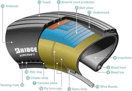
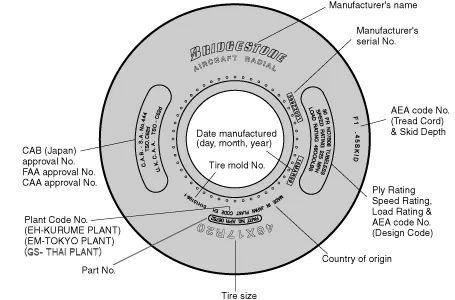
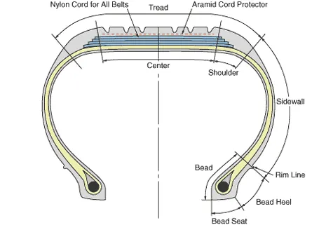
Tire Terminology
- Apex strip: A triangular piece of stiff rubber which is fitted onto the bead core to taper the rigid bead into the flexible body plies in the sidewall.
- Aramid cord protector: The tire is constructed with an aramid ply insert between the tread and the top belt to prevent damage to the tire belts.
- Bead heel: Outer edge of the bead.
- Bead toe: Inner edge of the bead.
- Belt plies: Angled belt plies that serve to add strength to the tire especially in the tread area.
- Chafer strip: Protective layer of rubber and fabric which prevents chafing between cord body plies and the wheel.
- Carcass plies: Layers of rubber-coated fabric plies which have the cords running radially from bead to bead. These provide the tire with strength in the sidewall area.
- Inner liner: A sheet of low permeable rubber laminated to the inside of the first casing ply of a tubeless tire to insure retention of air when the tire is inflated.
- Ply turn-ups: The turned-up ends of plies around the bead. Other plies lock the ends into place.
- Rim line: A-line provided near the beads to allow inspection of how the tire fits with the rim.
- Sidewall: The side area of the tyre is located between the shoulder and the beads. Composed of rubber, it protects the carcass from damage.
- Tread: The functions of the radial tread are the same as those defined for the bias tire.
- Under tread: A rubber layer provided for use in retreading the tire and which provides adhesion of tread to the tire carcass. Bridgestone makes this rubber layer thick enough to ensure a high number of retreads.
- Wire beads: Two-wire bundles (one for each bead) which help to maintain the shape of the tire and anchor it securely to the rim.
- Venting hole: The hole through which gas is vented from inside the carcass plies.
Balance marker
A balance marker, consisting of a red dot, is affixed on the sidewall of the tire immediately above the bead to indicate the lightweight point of the tire.
(iii) Rolling Resistance:
The Rolling resistance force is mainly Experienced by the Tyre when the vehicle moves over any surface. The rolling resistance force is given by the expression,
Frr = urr * (m.g)
Where
m.g = weight in Newton
urrr = coefficient of rolling resistance.
The coefficient of rolling resistance (or) depends on many factors like the Tyre Pressure, Tyre Temperature, Material of the Tyre, Thread pattern of the Tyre, and also the Road Roughness and Liquids on the Road. These factors determine the rolling resistance force.
(iv) Tyre Pressure:
The pressure generally is very high in an aircraft tire to reduce the rolling resistance and to withstand the weight. Usually, it will be around 200 to 300 psi of pressure and they change based on the type of the aircraft. Tests of airliner aircraft tyres have shown that they can sustain pressures of a maximum of 800 psi. Aircraft tyres are usually inflated with nitrogen to minimize expansion and contraction from extreme changes in ambient temperature and pressure experienced during flight.
(v) Brake force while Landing:
Aircraft disc brakes
Aircraft has disc rotors in the landing gear, used to break the wheels while touching the ground. These brakes are operated hydraulically or pneumatically.
Thrust reversers
Thrust reversers allow thrust from the engines to be used to slow the aircraft. This is also very effective in bringing down the speed of the aircraft. By using a negative angle plane, we are turning the wind that is coming into the propeller to flow in the opposite direction
Air Brake
Air brake dedicated flight control surface that works by increasing the drag force, air brakes are designed to increase drag while making little change to lift, resulting in a higher stall speed. These are some of the types of braking methods used to bring down the aircraft's speed while landing the flight.
Large drogue parachutes
It is used by several former and current military and civilian aircraft (examples include the American B-52 and the soviet Tu-134 and Tu-144) and in the Space Shuttle.
Objective No. (6):
To push or pull an aircraft by a towing vehicle, 3 types of forces will act on that vehicle. Those are -
(i) Rolling resistance force (ii) Aerodynamic drag force and (iii) Hill climbing force.
(i) Rolling resistance force(Frr): Rolling resistance is the force resisting the motion when a body rolls on a surface. It is the friction force that is needed to be overcome to move a vehicle. The kinetic energy of the wheels is partially converted into heat. The rolling resistance is proportional to the normal force perpendicular to the rolling wheel and is approximated by the rolling resistance coefficient urr. Therefore, the Equation that can be used for the rolling resistance force of the entire system is-
Frr = urr * m * g where, urr= Rolling resistance co-efficient (It depends on the tire material, tire structure, tire temperature, road roughness, road material, etc.) m= Total mass of the vehicle (vehicle mass + payload) in kg g = gravitational constant , that is 9.8 m/s^2
| urr of Car for different condition- | |
| CONDITION | urr |
| Tires on concrete or asphalt | 0.013 |
| Tires on rolled gravel | 0.02 |
| Tarmacadam | 0.025 |
| Unpaved road | 0.05 |
| Field | 0.1 - 0.35 |
Here in this case for towing vehicle for aircraft urr= 0.013
(ii) Aerodynamic drag force(Fad): Aerodynamic drag force is the force that is required to keep a vehicle moving. There is two-component of this force, one is shape drag (due to the shape of the vehicle) and another is skin friction (due to friction between air and skin of the vehicle). When the vehicle moves the velocity of air near the boundary is higher than the air surrounding it. Both the tug and the aircraft will experience some aerodynamic drag. For completeness, the aerodynamic drag force caused by the aircraft and towing vehicle can be given by Equation below-
Fad = (1/2) * ρ * V^2 * A * (Cd_t + Cd_a) where, ρ = Air density, that is normally 1.25 kg/m^3 A = Frontal area of the vehicle in m^2 Cd_t = Air drag co-efficient of towing vehicle (It depends on frontal area, shape, protrusions, ducts, air passage, etc.) Cd_a = Air drag co-efficient of aircraft (It depends on frontal area, shape, protrusions, ducts, air passage, etc.) v = Velocity of the vehicle in m/s
Concerning the drag equation, the term A simply refers to some reference area. For airplanes, this is generally the planform area of the wing The designers design an aircraft in such a way that the reference area is optimal. So, for calculation, this has been neglected.
| Cd for different types of vehicle- | |
| VEHICLE TYPE | Cd |
| Open Convertible | 0.5 - 0.7 |
| Van body | 0.5 - 0.7 |
| Ponton body | 0.4 - 0.55 |
| wedge-shaped body, head lamps and bumpers are integrated into the body, covered unready optimized cooling airflow |
0.3 - 0.4 |
| Motor cycle | 0.6 - 0.7 |
| racing car | 0.2 - 0.25 |
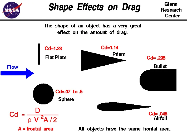 In this case air drag co-efficient for towing vehicle(Cd_t)= 0.5 and for aircraft or payload(Cd_a)= 0.045.
(iii) Hill climbing force(Fhc): Hill climbing force is the force needed to move the vehicle in an up gradient. To Hill Climbing force the expression of the equation is given below-
Fhc = m * g * sinφ where, m = Total mass of the vehicle(vehicle mass + payload) in kg g = Gravitational constant that is 9.8 m/s^2 φ = up gradient angle or inclination angle in radian
In this case up gradient angle(φ) = 0, as there is no inclination.
Push/Pull Power Calculation of Towing Vehicle-
Let's assume,the towing vehicle mass = 50000 Kg,
the aircraft mass or payload on towing vehicle = 183700 Kg,
total mass of the vehicle(m) = (50000+183700) = 233700 Kg,
towing vehicle fontal area(A) = 20 m^2
speed of the vehicle(V) = 30 Km/hr = 8.333 m/s
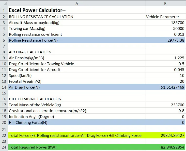
Rolling Resistance Force(Frr) = urr * m * g =0.013 * (50000+183700) * 9.8 =29,773.38 N
Aerodynamic Drag Force(Fad) = (1/2) * ρ * V^2 * A * (Cd_t + Cd_a)= (1/2) * 1.225 * (2.778)^2 * 20 * (0.5+0.045)= 51.514 N
Hill Climbing Force(Fhc) = m * g * sinφ =(50000+183700) * 9.8 * sin0 = 0 N
Total required traction power(Tf) = Frr + Fad + Fhc =29773.38 + 51.514 + 0 =29824.894 N
Push/Pull Power Calculation of Towing Vehicle-
Objective No. (7):
Table for the necessary assumed parameters-
| Assumption For Powertrain Design- | |
| Aircraft Mass | 183700 Kg |
| Towing Vehicle Mass | 50000 Kg |
| Rolling Resistance Co-efficient | 0.013 |
| Air Density | 1.225 kg/m^3 |
|
Towing Vehicle Drag Co-efficient |
0.5 |
| Aircraft Drag Co-efficient | 0.045 |
| Frontal area | 20 m^2 |
| Inclination Angle | 0 rad |
| Tyre Pressure | 203 PSI/14 bar |
| Towing Velocity(V) |
10km/h =2.778m/s |
| Towing Time(t) | 2 min |
| Radius of the towing vehicle wheel |
0.38 m |
Therefore from the excel power calculator we have got the necessary Traction force(F) quantity that is = 29824.89427 N
and Required power(P) = F * V = 29824.894 * 2.778 =82846.928 W = 82.846 KW
As we know Torque(T) = Force(F) * Wheel radious(r) So, from the above equation we have got the required torque(T) = 29824.894 * 0.38 = 11333.45972 N-m.
Required Energy(E) for towing application based on the assumed time, that is E = P * t = 82.846 * (120/3600)= 2.761 KWh
For this application, an Induction motor or a BLDC can be used with a proper gear system.
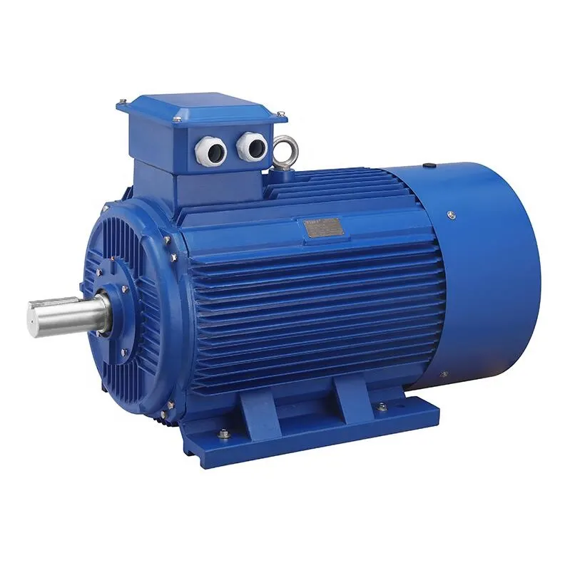 Fig- Induction Asynchronous motor
| Induction Motor Rating- | ||||||
| Output Mechanical Power |
Horse Power |
Input In term of Mechanical Power |
No of Phases |
Input Voltage | Input Current | Efficiency |
| 90 KW | 120 H.P | 95.642 KW | 3 | 380 V | 163.3 A | 94.10% |
| 400 V | 155.1 A | |||||
| 415 V | 149.5 A |
The motor output power is the input power of the towing vehicle so to obtain maximum speed, the duty cycle needed is calculated as below- Duty Cycle = Output Power/Input Power = (82.846/90)*100 = (0.921*100)%, so the duty cycle will be 92.1% The duty cycle range to control the aircraft speed from zero to highest is from 0 to 92.1 %
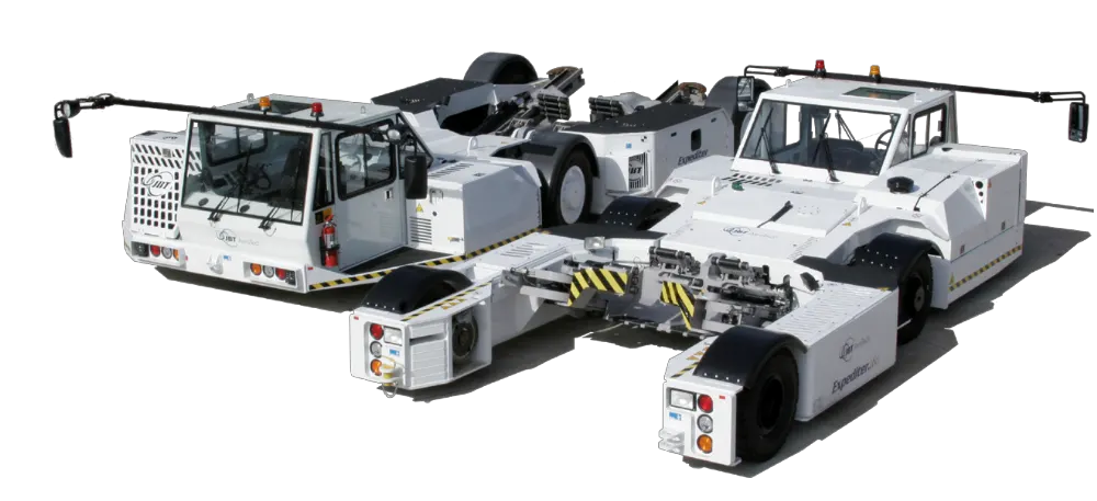 Towing Vehicles
Towing Vehicle Simulink Powertrain Block model- 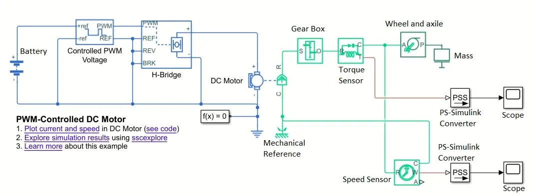 Though an Induction motor has been chosen for this application here this Simulink model is built based on a DC motor.
Torque Characteristic- 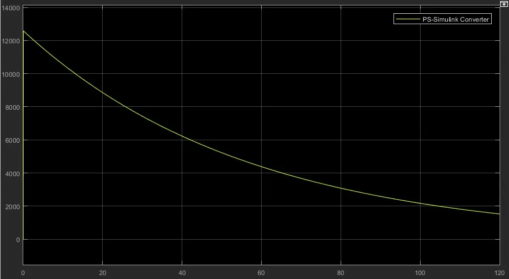 Here torque is in unit of N-m.
Speed Characteristic- 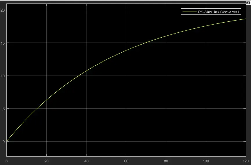 Here speed is in the unit of rad/sec.
Block Diagram of Powertrain for Towing Vehicle- 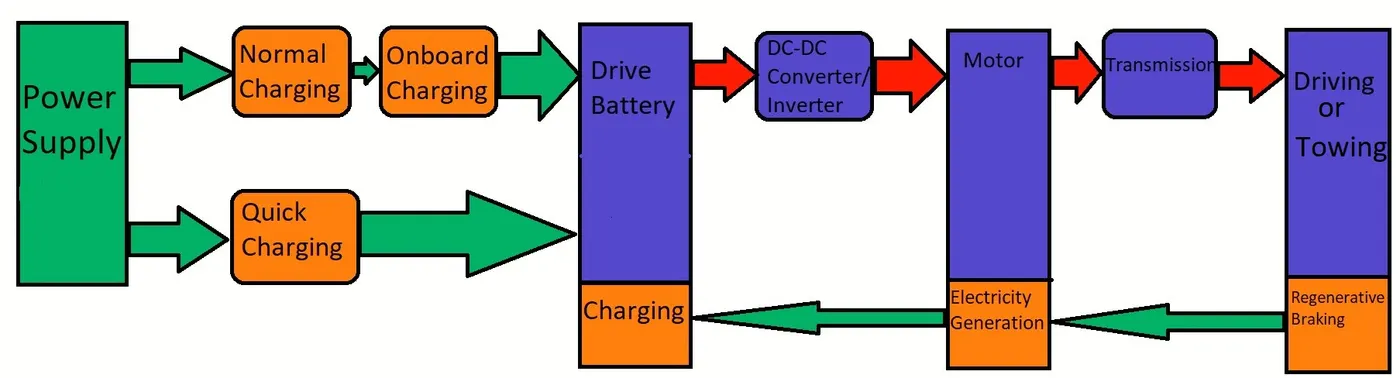
Electric Vehicles, consist of a battery, connected to an electric motor (either AC or DC) via an inverter and a motor controller. As automotive batteries generally operate on DC, while the gird operates AC, a converter is needed to transfer power to the battery. One of the key advantages of an EV is its much higher levels of energy efficiency. Typically an EV will achieve a system efficiency of 80% from battery to wheel (roughly 60% from the grid to wheel), while with a conventional IC engine it’s more like 15-25%. This is large because an IC engine is a “heat engine” (i.e. it has to burn fuel and produce heat to operate) and much of all that heat is simply wasted.
Conclusions: All the problem statements are answered and all the needed diagrams or results are also provided.
References:
- https://aviation.stackexchange.com/questions/12956/what-are-different-types-of-weights-of-an-aircraft
- https://en.wikipedia.org/wiki/Aircraft_gross_weight
- https://www.grc.nasa.gov/www/k-12/VirtualAero/BottleRocket/airplane/acg.html
- https://m.blog.naver.com/fltops/110226753
- https://en.wikipedia.org/wiki/List_of_airliners_by_maximum_takeoff_weight
- https://en.wikipedia.org/wiki/Pushback
- https://www.aircraftsystemstech.com/p/aircraft-tires-and-tubes-aircraft-tires.html
- https://www.bridgestone.com/products/speciality_tires/aircraft/products/basicstructure/index.html#:~:text=Aircraft%20tires%20are%20classified%20by,and%20Three%20Part%20Type%20tires.
- https://evreporter.com/ev-powertrain-components/#:~:text=An%20EV%20powertrain%20has%2060,The%20components%20are%20described%20below.&text=Battery%20Pack%20%E2%80%93%20The%20battery%20pack,direct%20current%20(DC)%20output.
- https://webstor.srmist.edu.in
- https://www.aviationpros.com
- https://www.aviationhunt.com
- https://arc.aiaa.org
- https://code7700.com
- https://flightsafety.org
- https://repository.tudelft.nl
- https://www.nata.aero/agso/astgcache/1a96deb7-7c34-46db-ace7-df80a2d693ce.pdf