DC Motor Control using MATLAB
AIM :
- Run a MATLAB demo 'Speed Control of a DC Motor using BJT H-bridge' modify the model such that armature current doesnt shoot up when motor changes direction from forward to reverse.
- Refer to help section of the 'Four Quadrant Chopper DC Drive(DC7) Block' compare it with H-Bridge model
- Explain in a brief about operation of BLDC motor.
1, Speed Control of a DC Motor using BJT H-Bridge modify the model such that armature current doesnt shoot up when motor changes direction from forward to reverse.
Speed Control of a DC Motor using BJT H-Bridge
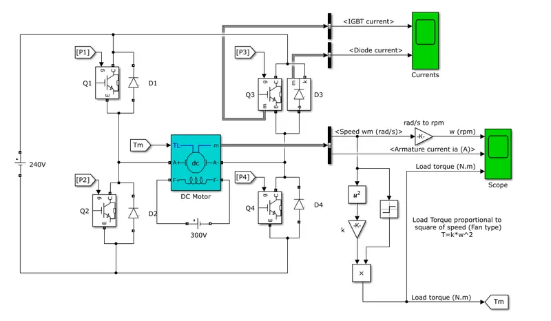
The Bipolar Junction Transistor (BJT) when used for power switching applications, operates as an IGBT. When it is conducting (BJT operating in the saturated region), a forward voltage Vf is developed between collector and emitter (in the range of 1 V). Therefore, the IGBT block can be used to model the BJT device.
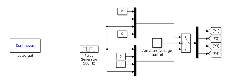
The IGBT block does not simulate the gate current controlling the BJT or IGBT. The switch is controlled by a Simulink® signal (1/0). The DC motor uses the preset model (5 HP 24V 1750 rpm). It simulates a fan type load (where Load torque is proportional to square of speed). The armature mean voltage can be varied from 0 to 240 V when the duty cycle (specified in the Pulse Generator block) is varied from 0 to 100%.
The H-bridge consists of four BJT/Diode pairs (BJT simulated by IGBT models). Two transistors are switched simultaneously: Q1 and Q4 or Q2 and Q3. When Q1 and Q4 are fired, a positive voltage is applied to the motor and diodes D2-D3 operate as free-wheeling diodes when Q1 and Q4 are switched off. When Q2 and Q3 are fired, a negative voltage is applied to the motor and diodes D1-D4 operate as free-wheeling diodes when Q2 and Q3 are switched off.
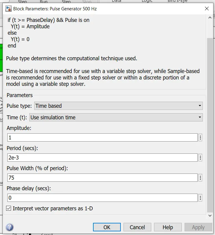
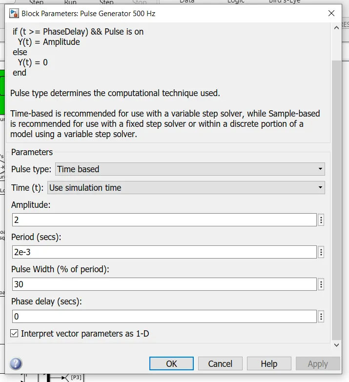
Running the simulation with the following Pulse Generator configuaration :
OUTPUT :
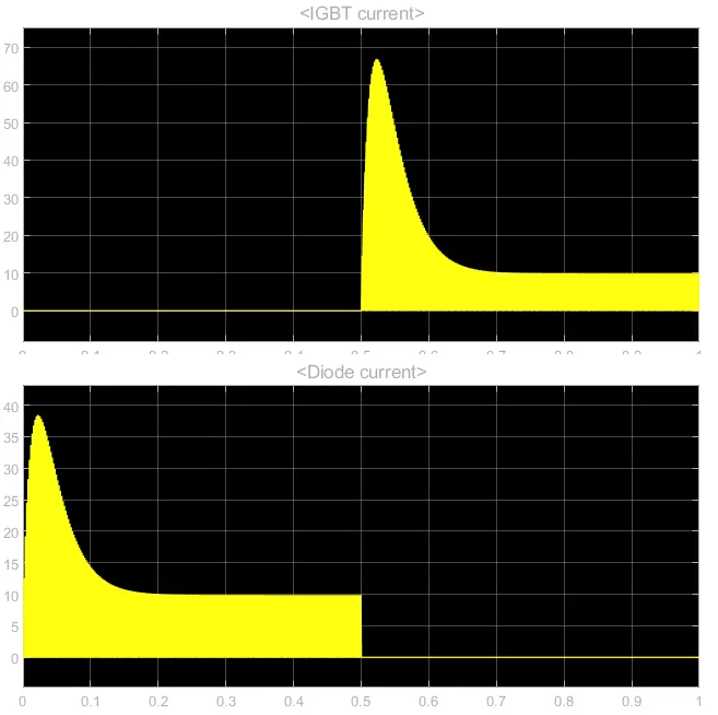
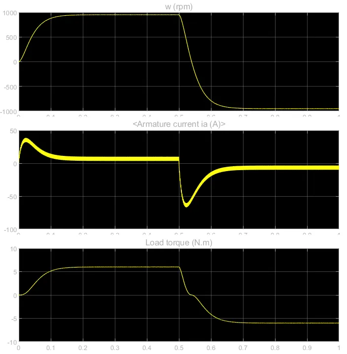
So we can see armature current is changing significantly so in order to control the violation of armature current, we have changed the duty cycle of the battery and observed the variation in armature current,
Change in Pulse width :
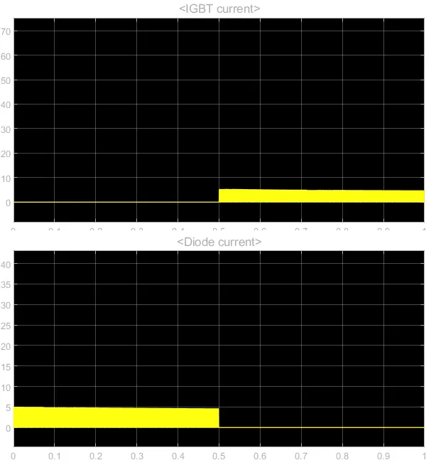
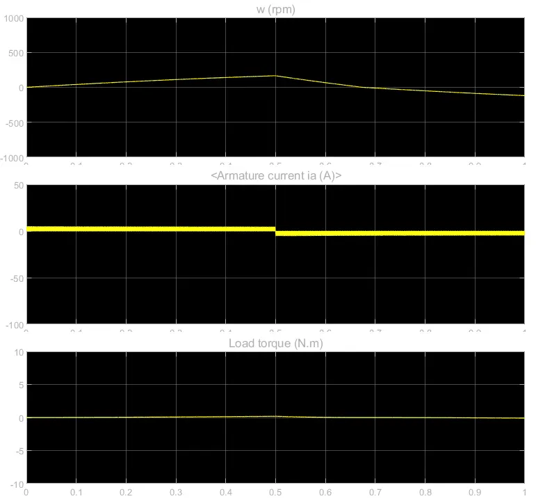
So from the above change in pulse speed we see that the shoot out of armature current is gone completely.
2, Refer to help section of the 'Four Quadrant Chopper DC Drive(DC7) Block' compare it with H-Bridge model
Four Quadrant Chopper DC Drive :
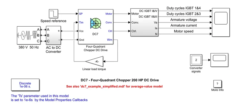
The 200 HP DC motor is separately excited with a constant 150 V DC field voltage source. The armature voltage is provided by an IGBT converter controlled by two PI regulators. The converter is fed by a 515 V DC bus obtained by rectification of a 380 V AC 50 Hz voltage source. In order to limit the DC bus voltage during dynamic braking mode, a braking chopper has been added between the diode rectifier and the DC7block.
The first regulator is a speed regulator, followed by a current regulator. The speed regulator outputs the armature current reference (in p.u.) used by the current controller in order to obtain the electromagnetic torque needed to reach the desired speed. The speed reference change rate follows acceleration and deceleration ramps in order to avoid sudden reference changes that could cause armature over-current and destabilize the system. The current regulator controls the armature current by computing the appropriate duty ratios of the 5 kHz pulses of the four IGBT devices (Pulse Width Modulation). For proper system behaviour, the instantaneous pulse values of IGBT devices 1 and 4 are opposite to those of IGBT devices 2 and 3. This generates the average armature voltage needed to obtain the desired armature current. In order to limit the amplitude of the current oscillations, a smoothing inductance is placed in series with the armature circuit.
The 200 HP DC motor is separately excited with a constant 150 V DC field voltage source. The armature voltage is provided by an IGBT converter controlled by two PI regulators. The converter is fed by a 515 V DC bus obtained by rectification of a 380 V AC 50 Hz voltage source. In order to limit the DC bus voltage during dynamic braking mode, a braking chopper has been added between the diode rectifier and the DC7block.
The first regulator is a speed regulator, followed by a current regulator. The speed regulator outputs the armature current reference (in p.u.) used by the current controller in order to obtain the electromagnetic torque needed to reach the desired speed. The speed reference change rate follows acceleration and deceleration ramps in order to avoid sudden reference changes that could cause armature over-current and destabilize the system. The current regulator controls the armature current by computing the appropriate duty ratios of the 5 kHz pulses of the four IGBT devices (Pulse Width Modulation). For proper system behaviour, the instantaneous pulse values of IGBT devices 1 and 4 are opposite to those of IGBT devices 2 and 3. This generates the average armature voltage needed to obtain the desired armature current. In order to limit the amplitude of the current oscillations, a smoothing inductance is placed in series with the armature circuit.
H-Bridge Motor driving circuit :
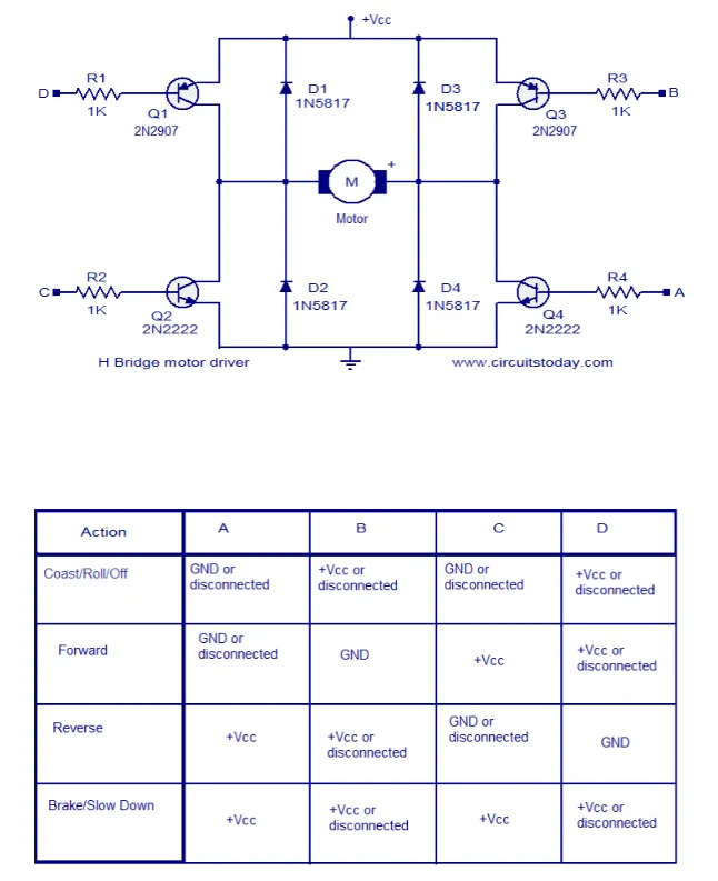
H Bridge is a very effective method for driving motors and it finds a lot of applications in many electronic projects especially in robotics.
The circuit shown here is a typical four transistor H Bridge. The diodes D1 to D4 provide a safer path for the back emf from the motor to dissipate and thus it protects the corresponding bipolar transistors from damage. Resistors R1 to R4 limit the base current of the corresponding transistors. Working of this circuit is very easy to understand. When terminal D is grounded and A is pulled to +Vcc, transistors Q1 and Q4 will be on and current passes through the motor from left to right. When terminal B is grounded and C is pulled to +Vcc, transistors Q3 and Q2 will be on and current passes through the motor from right to right making the motor to rotate in the opposite direction.
Comparison :
Four quadrant dc chopper model requires current for each sector and consists of four-quadrant forward motoring, forward regenerative braking, reverse motoring, and reverse regenerative braking where as H-Bridge consists of two operations they are forward motoring and reverse motoring. H-Bridge is used in robotics technology.
3, BLDC Motor :
In a brushed DC motor, the rotor spins 180-degrees when an electric current is run to the armature. To go any further, the poles of the electromagnet must flip. The brushes, as the rotor spins, make contact with the stator, flipping the magnetic field and allowing the rotor to spin a full 360-degrees.
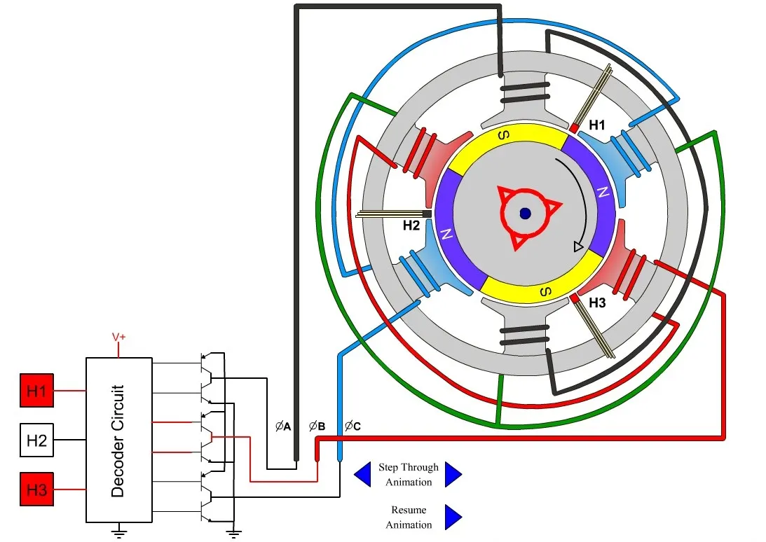
A brushless DC motor is essentially flipped inside out, eliminating the need for brushes to flip the electromagnetic field. In brushless DC motors, the permanent magnets are on the rotor, and the electromagnets are on the stator. A computer then charges the electromagnets in the stator to rotate the rotor a full 360-degrees.
Used of BLDC Motors :
rushless DC motors typically have an efficiency of 85-90%, while brushed motors are usually only 75-80% efficient. Brushes eventually wear out, sometimes causing dangerous sparking, limiting the lifespan of a brushed motor. Brushless DC motors are quiet, lighter and have much longer lifespans. Because computers control the electrical current, brushless DC motors can achieve much more precise motion control.
Because of all these advantages, brushless DC motors are often used in modern devices where low noise and low heat are required, especially in devices that run continuously. This may include washing machines, air conditioners and other consumer electronics. They may even be the main power source for service robots, which will require very careful control of force for safety reasons.
Brushless DC motors provide several distinct advantages over other types of electric motors, which is why they’ve made their way into so many household items and may be a major factor in the growth of service robots inside and outside of the industrial sector.