Flow over an airfoil
FLOW OVER AN AIRFOIL NACA-2415
AIM :
CFD analysis of air flow over a NACA-2415 airfoil at various angles of attack and compare the lift and drag force. The simulation is carried out at various angles of attack from `0^o` to `10^o` with an interval of `2^o`. The velocity and pressure distribution over NACA-2415 airfoil for different angle of attacks are presented along with comparison between Lift Force and Drag Force.
NACA-2415 data file : NACA-2415
THEORY :
An airfoil-shaped body moving through a fluid produces an aerodynamic force. The component of this force perpendicular to the direction of motion is called lift. The lift on an airfoil is primarily the result of its angle of attack. When oriented at a suitable angle, the airfoil deflects the oncoming air (for fixed-wing aircraft, a downward force), resulting in a force on the airfoil in the direction opposite to the deflection. This force is known as aerodynamic force and can be resolved into two components: lift and drag.
Most foil shapes require a positive angle of attack to generate lift, but cambered airfoils can generate lift at zero angle of attack. This "turning" of the air in the vicinity of the airfoil creates curved streamlines, resulting in lower pressure on one side and higher pressure on the other. This pressure difference is accompanied by a velocity difference, via Bernoulli's principle, so the resulting flow field about the airfoil has a higher average velocity on the upper surface than on the lower surface.
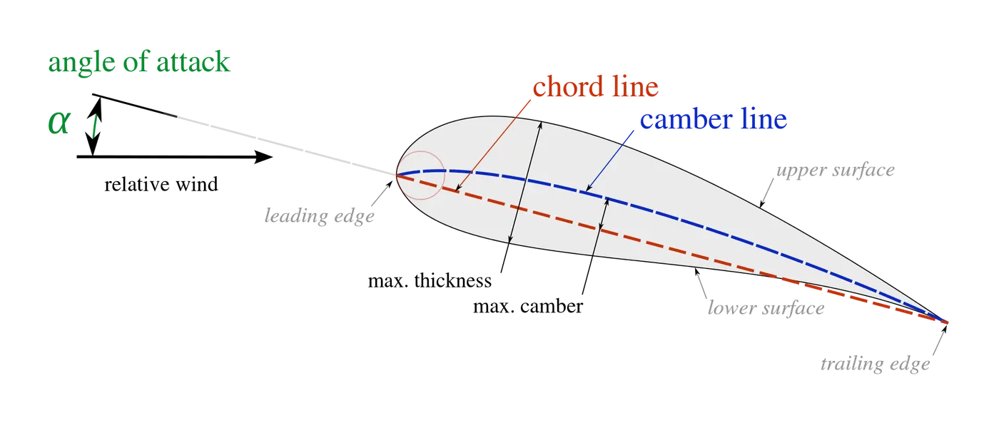
- The suction surface (upper surface) is generally associated with higher velocity and lower static pressure.
- The pressure surface (lower surface) has a comparatively higher static pressure than the suction surface. The pressure gradient between these two surfaces contributes to the lift force generated for a given airfoil.
- The leading edge is the point at the front of the airfoil that has maximum curvature.
- The trailing edge is defined similarly as the point of maximum curvature at the rear of the airfoil.
- The chord line is the straight line connecting leading and trailing edges.
PARAMETERS :
- NACA-2415 data is obtained.
- External flow simulation with Time dependent study
- Medium = Air
- Pressure = 101325 Pa
- Temperature = 293.2 K
- Velocity (X-Axis) = 700m/s
PROCEDURE :
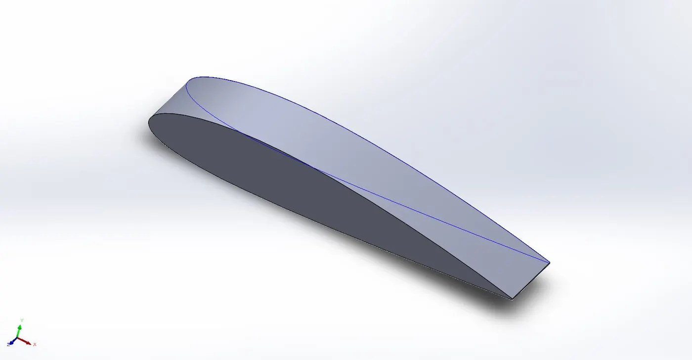
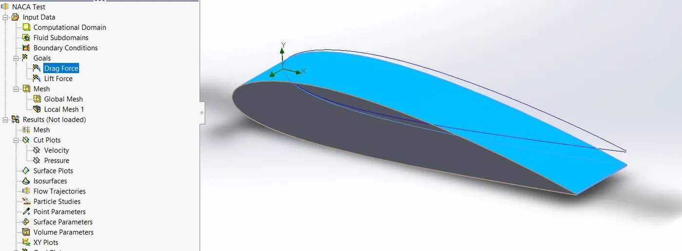
- Input the airfoil curve from the NACA_2415.txt file
- Extrude it after converting the curve into a solid sketch.
- Select the flow simulation wizard with medium as "air" and the above mentioned parameters.
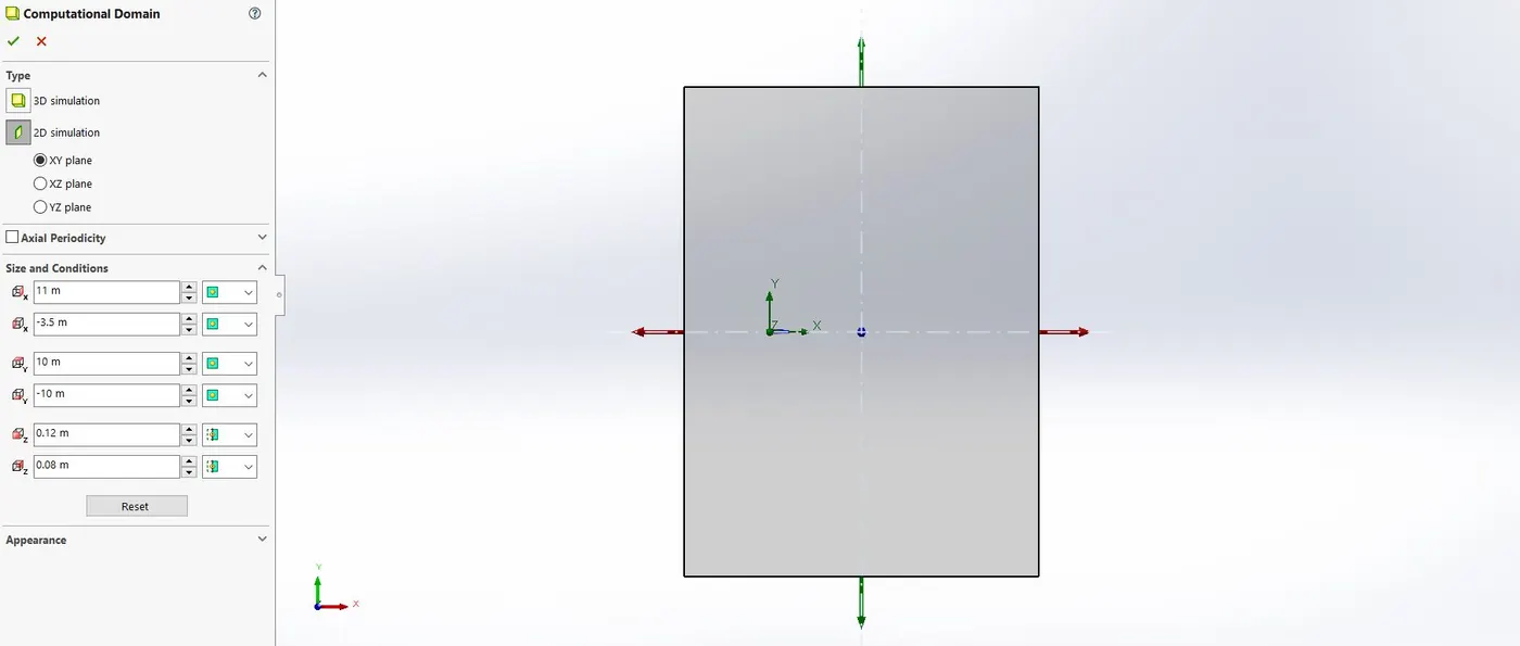
- Set the computational domain to 2D (XY axis) increase the X and Y axis domain so the flow wont deflect during simulation.
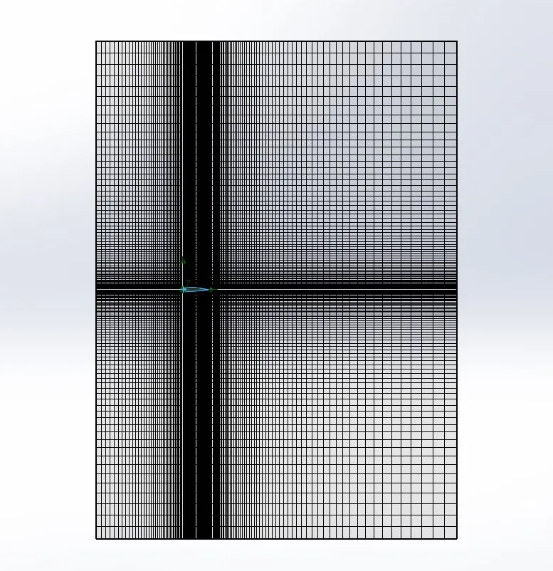
- Define a local mesh on the surface of the airfoil with more fine refinement.
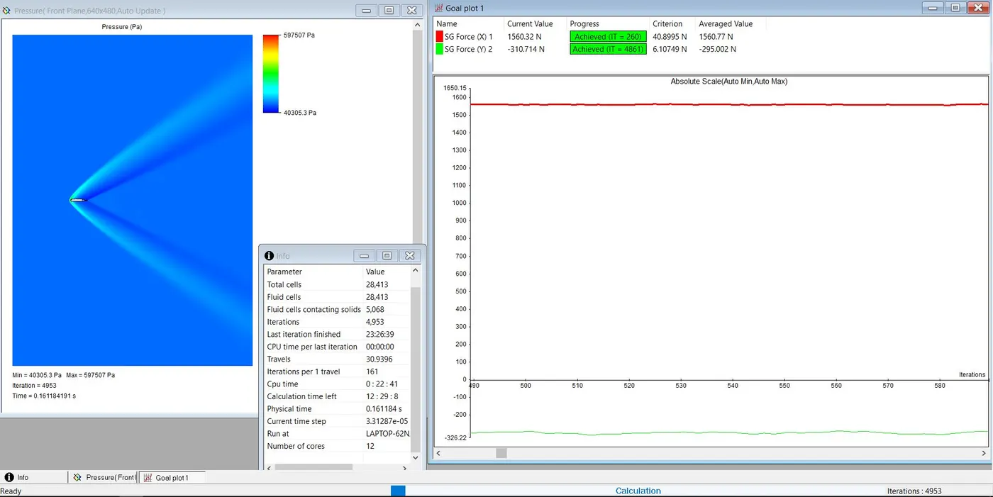
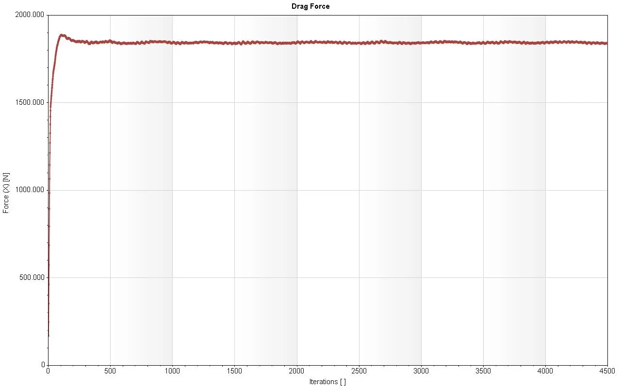
- Set surface goals : Forces along X and Y axis to get the drag and lift forces.
- Run the simulation.
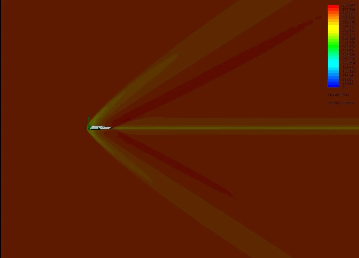
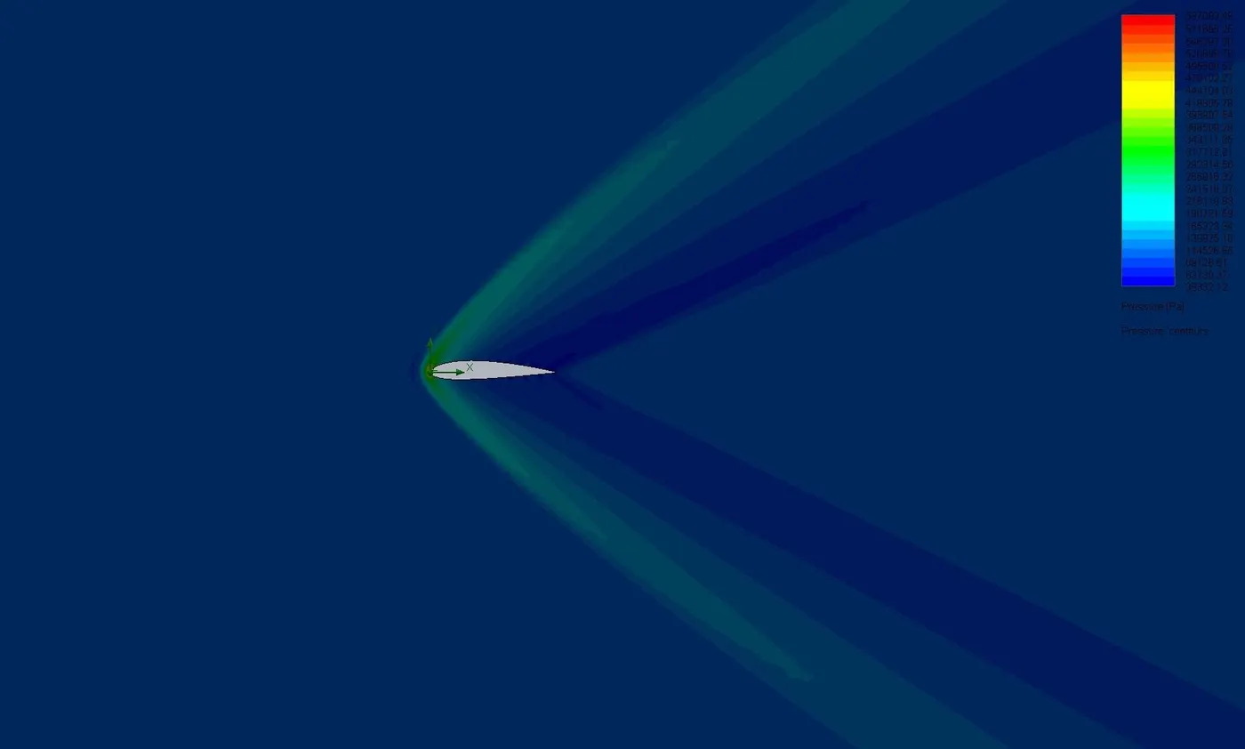
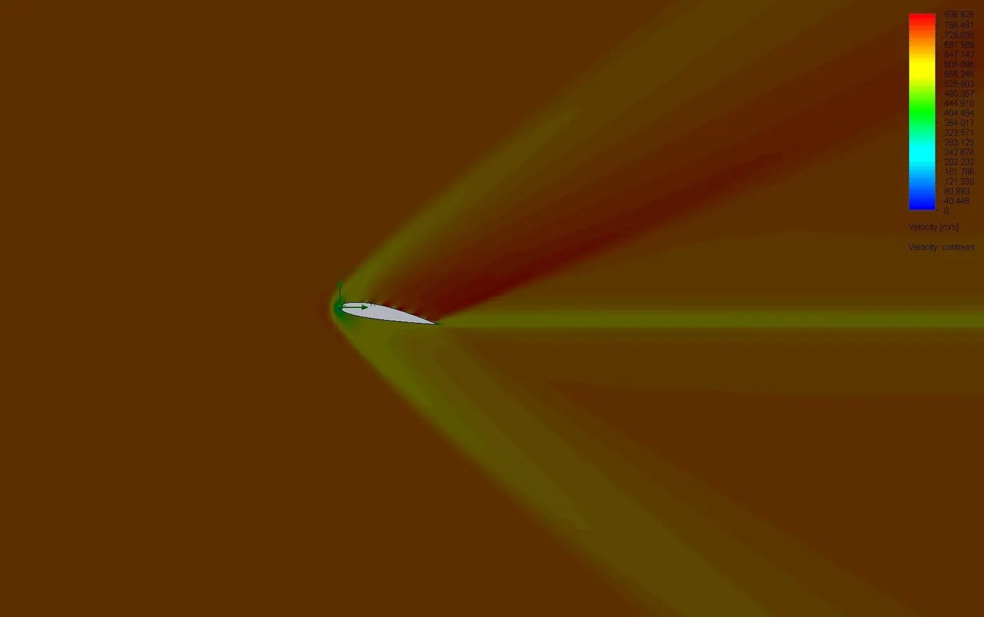
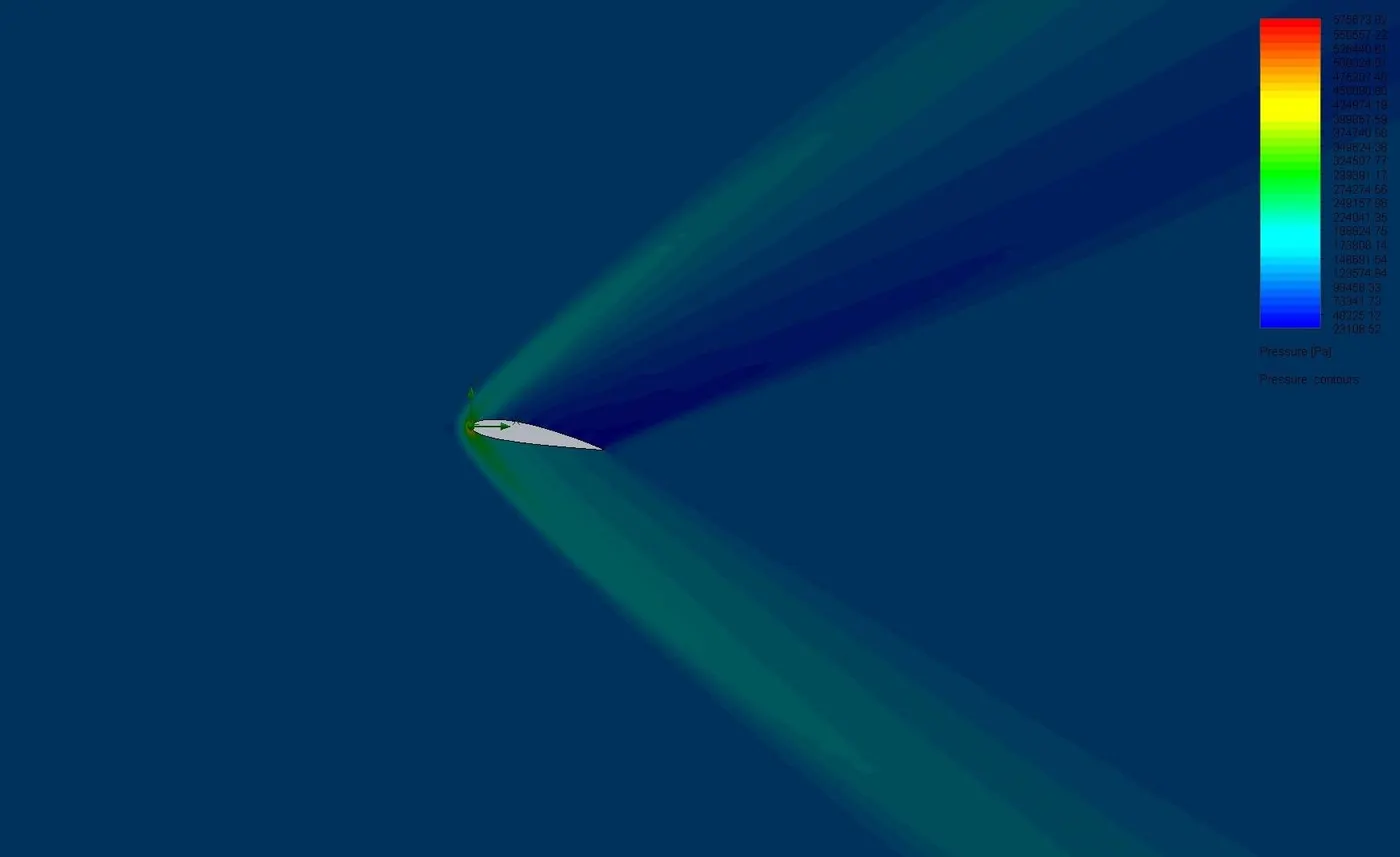
- Insert cut plots to get the velocity and pressure contours.
- Insert goal plots to obtain the drag and lift force results.
NACA-2415 :
GLOBAL MESH :
COMPUTATIONAL DOMAIN :
SURFACE GOALS :
SG FORCE (X) = DRAG FORCE
SG FORCE (Y) = LIFT FORCE
RESULTS AND OBSERVATION :
Case 1 : Angle of attack at `0^o`
| VELOCITY PLOT | PRESSURE PLOT |
 |
 |
SIMULATION :
| DRAG FORCE | LIFT FORCE |
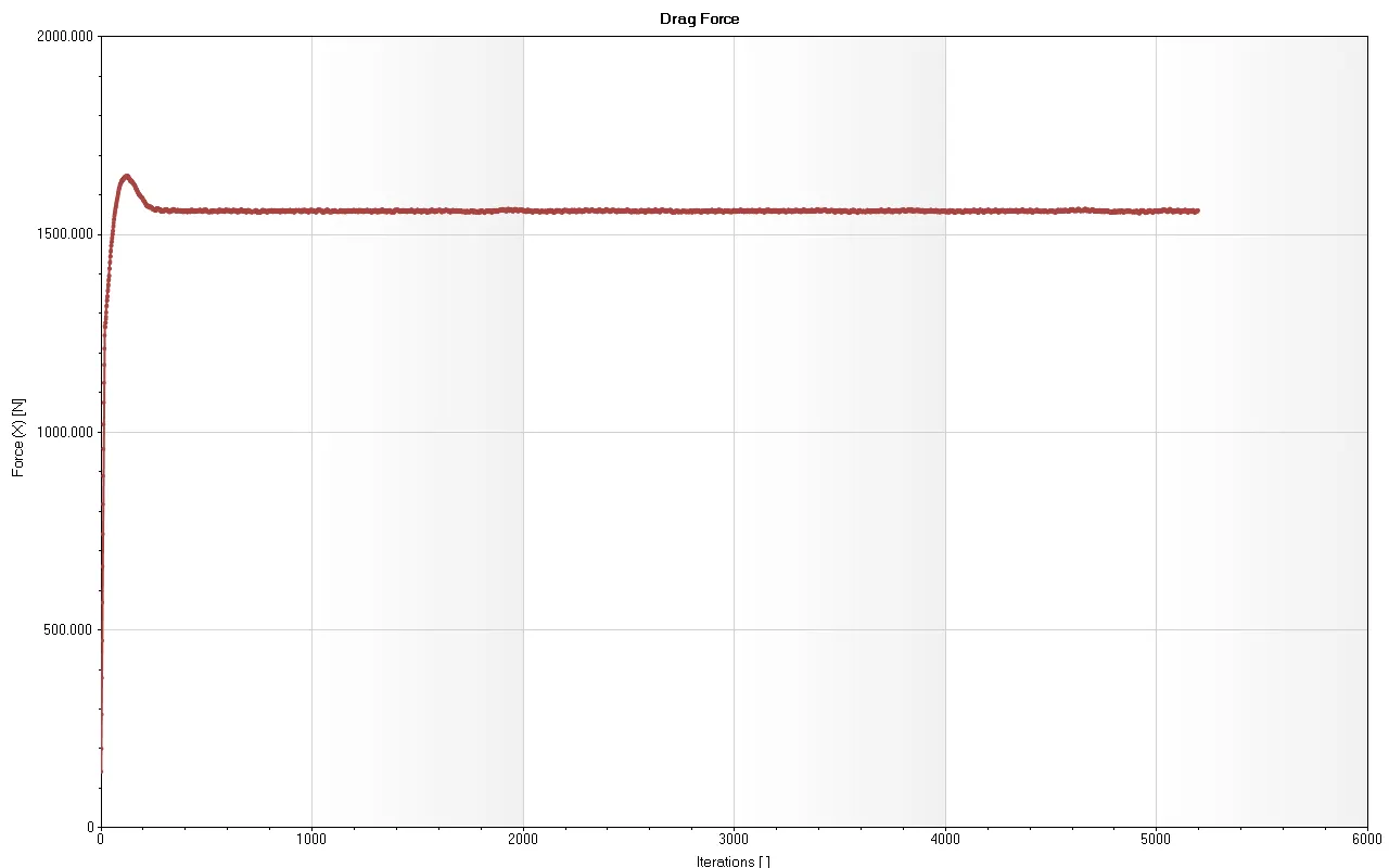 |
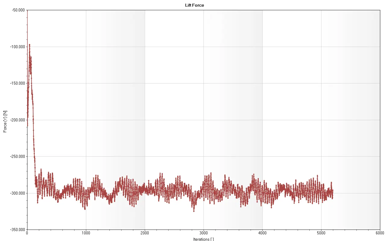 |
DRAG AND LIFT FORCE DATA :

Case 2 : Angle of attack at `2^o`
| VELOCITY PLOT | PRESSURE PLOT |
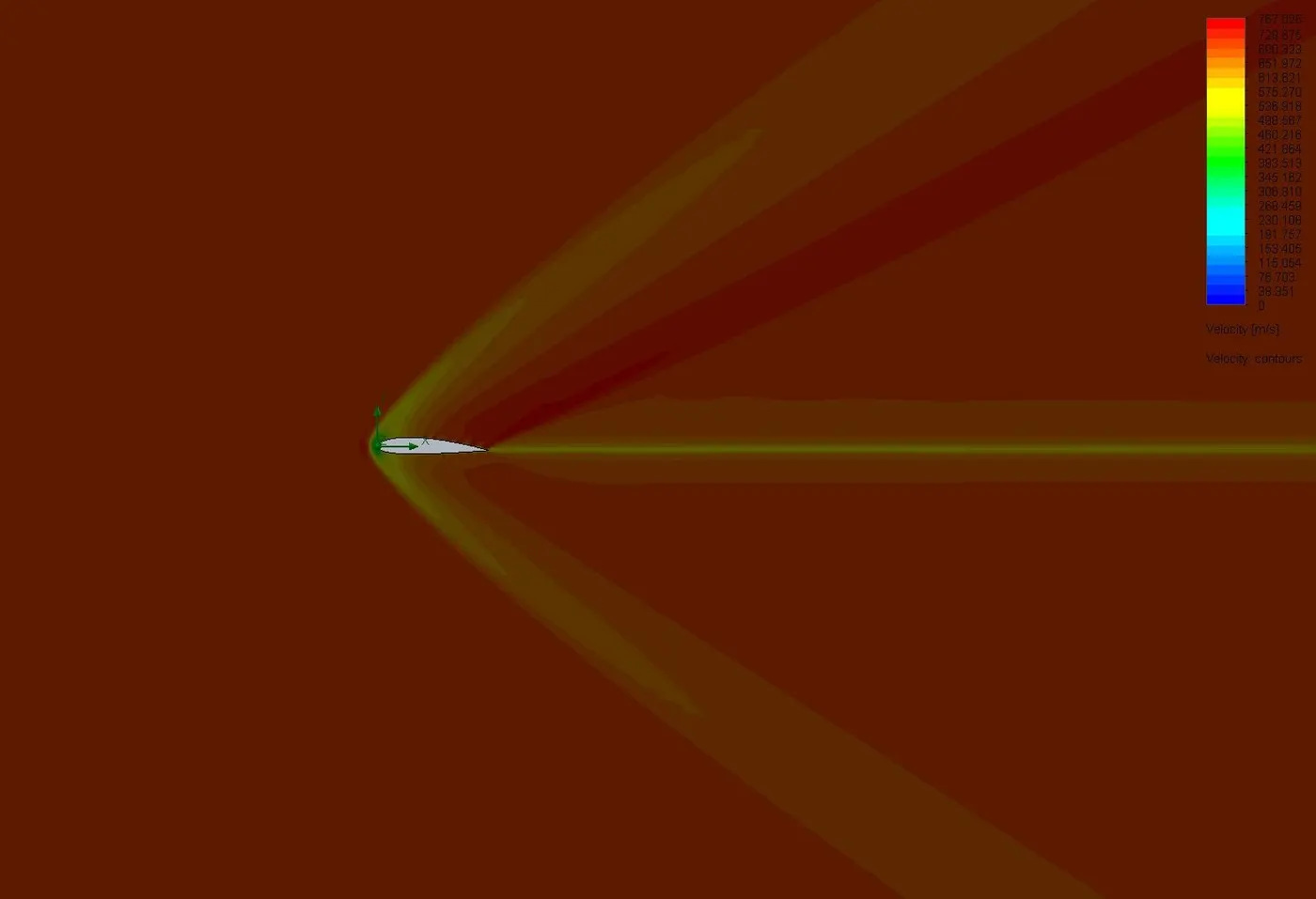 |
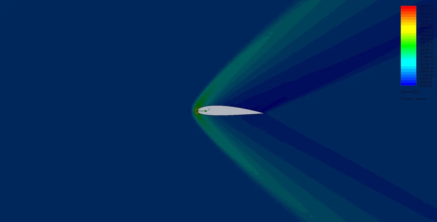 |
SIMULATION :
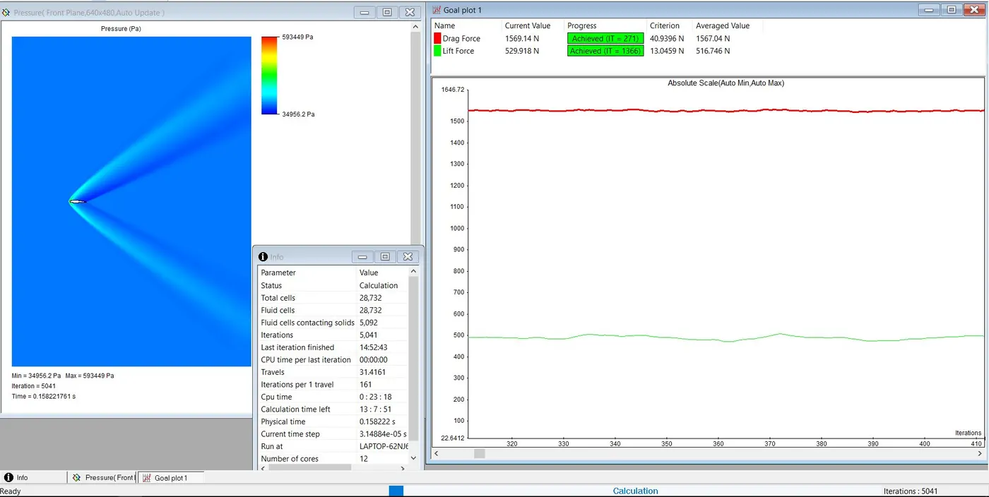
| DRAG FORCE | LIFT FORCE |
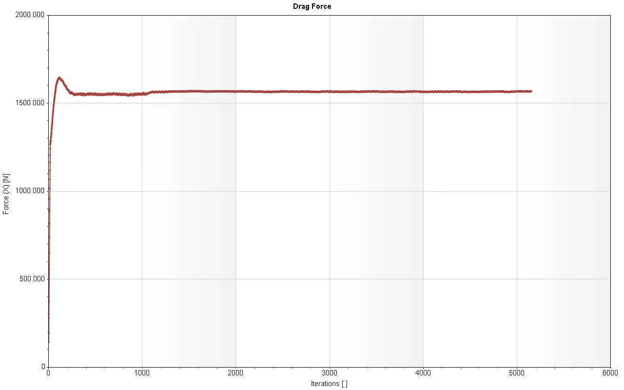 |
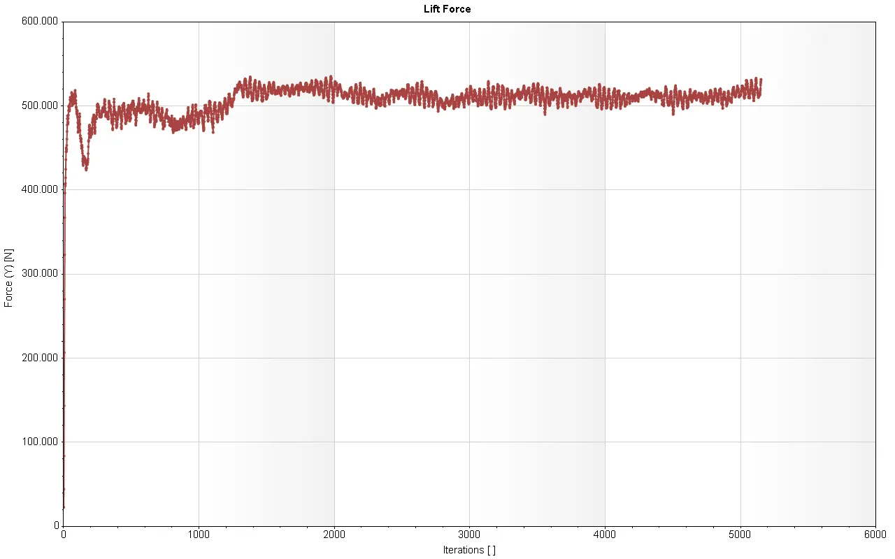 |
DRAG AND LIFT FORCE DATA :

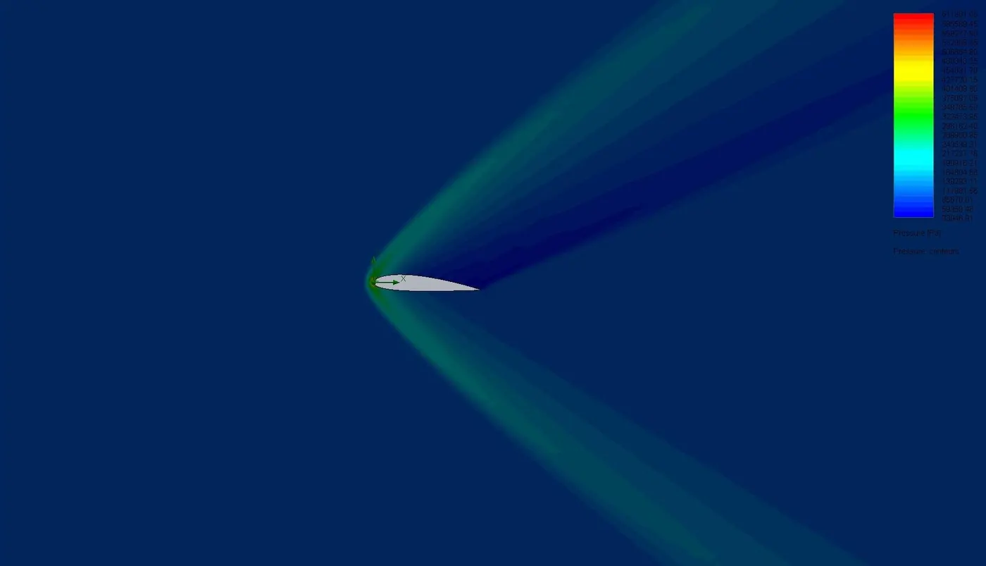
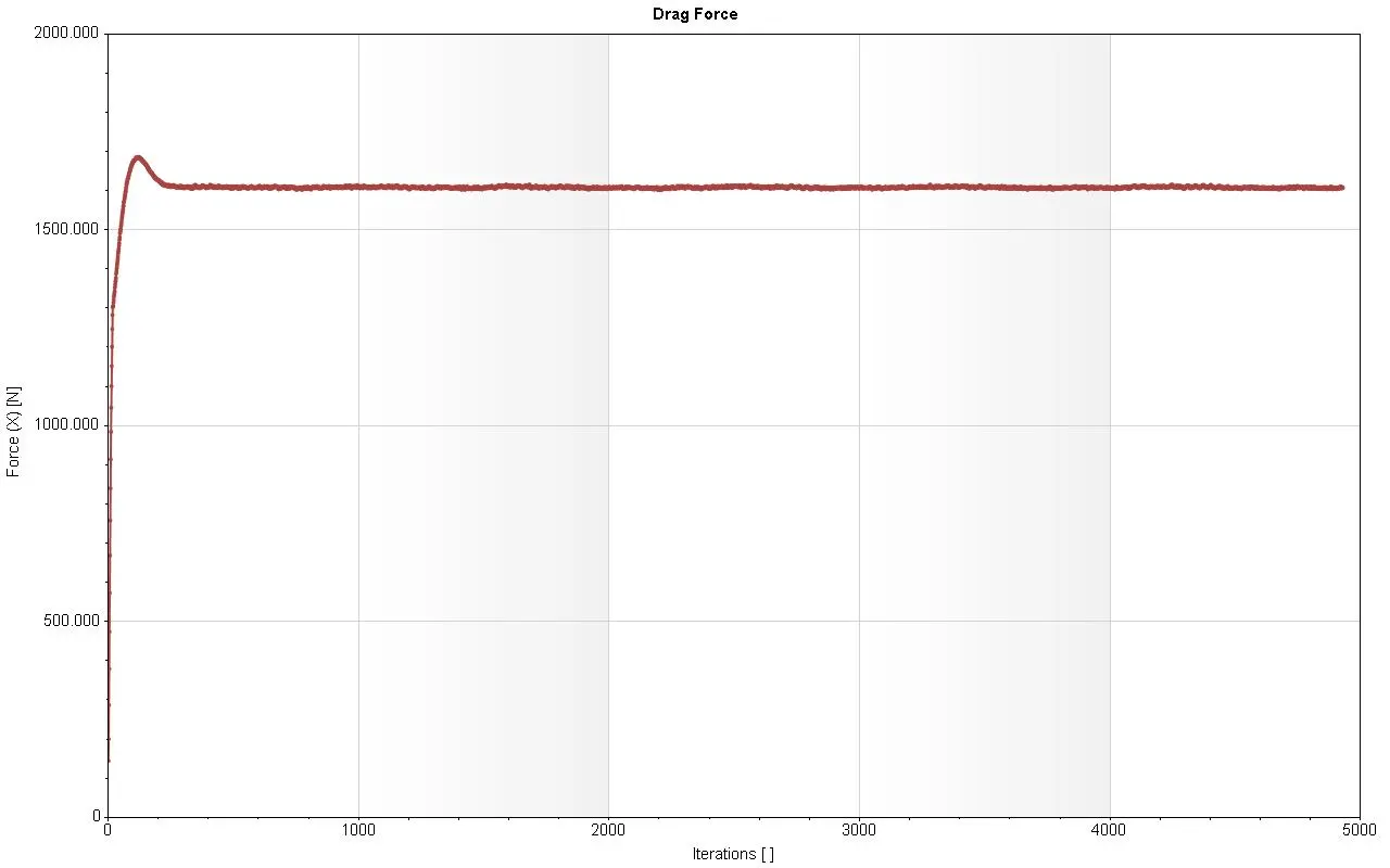
Case 3 : Angle of attack at `4^o`
| VELOCITY PLOT | PRESSURE PLOT |
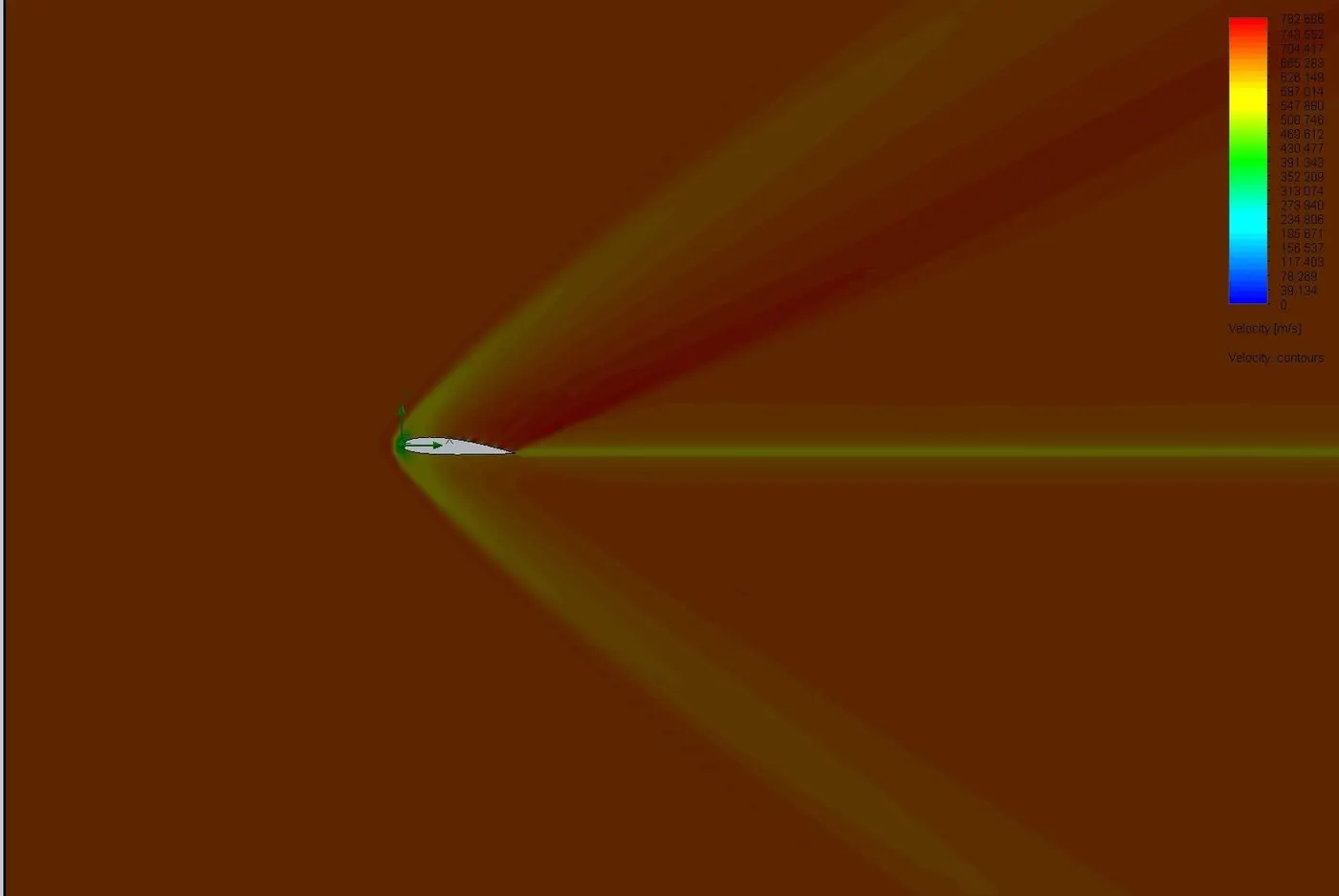 |
 |
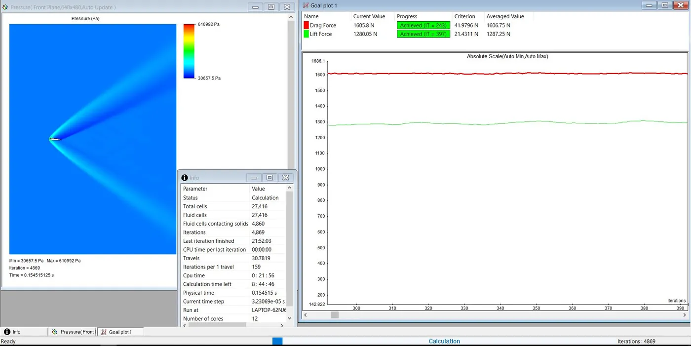
SIMULATION :
| DRAG FORCE | LIFT FORCE |
 |
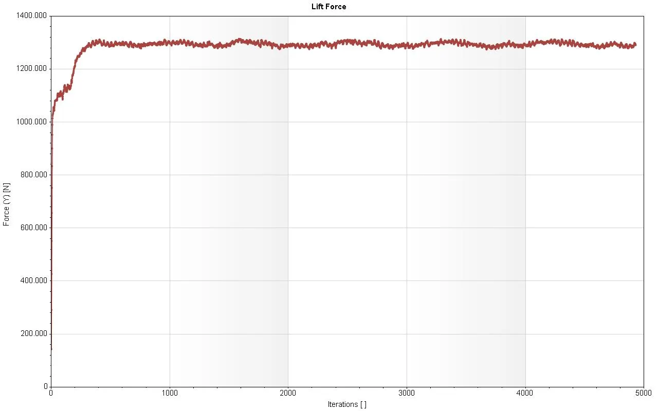 |
DRAG AND LIFT FORCE DATA :

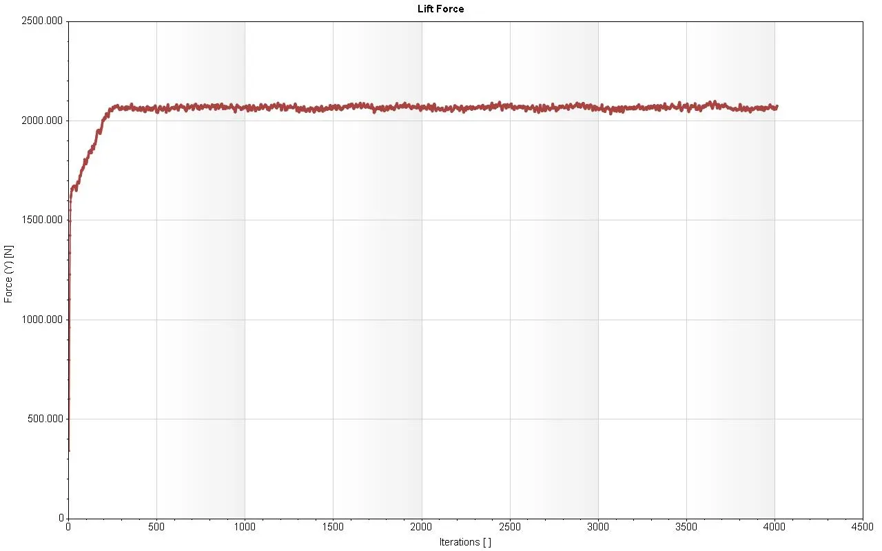
Case 4 : Angle of attack at `6^o`
| VELOCITY PLOT | PRESSURE PLOT |
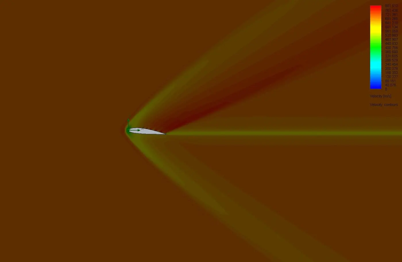 |
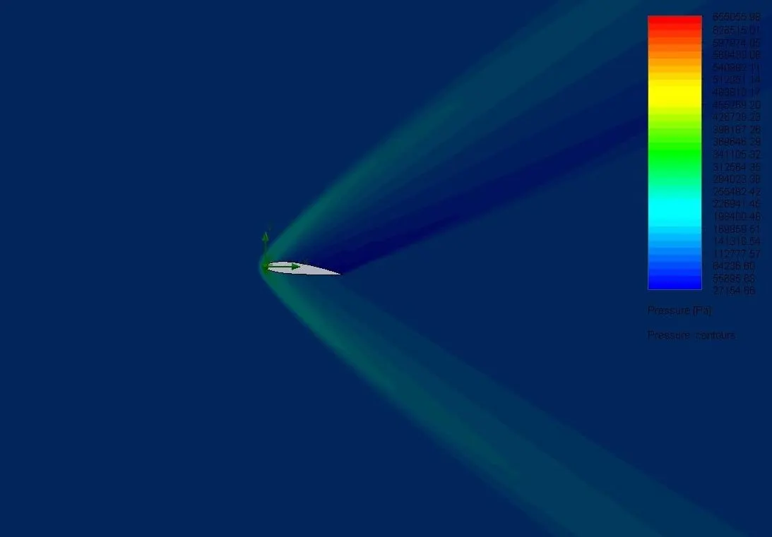 |
SIMULATION :
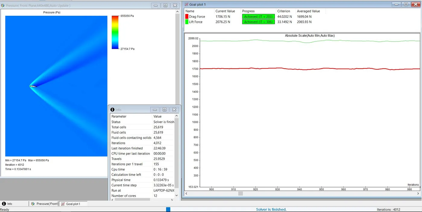
| DRAG FORCE | LIFT FORCE |
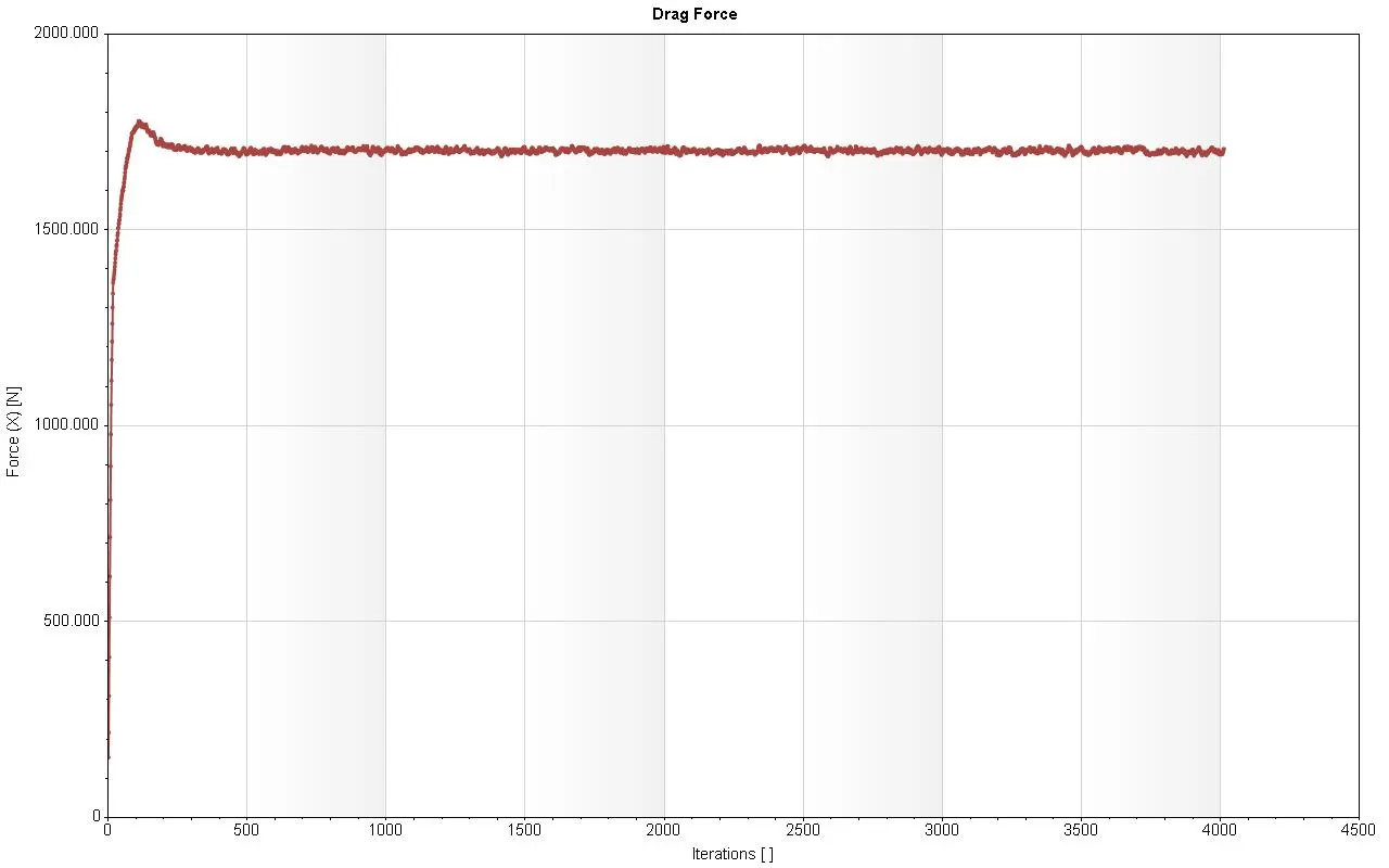 |
 |
DRAG AND LIFT FORCE DATA :

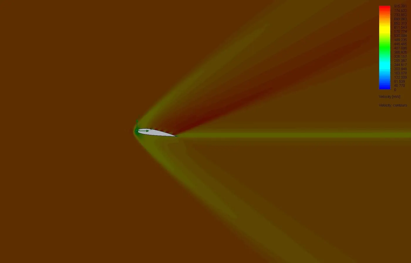
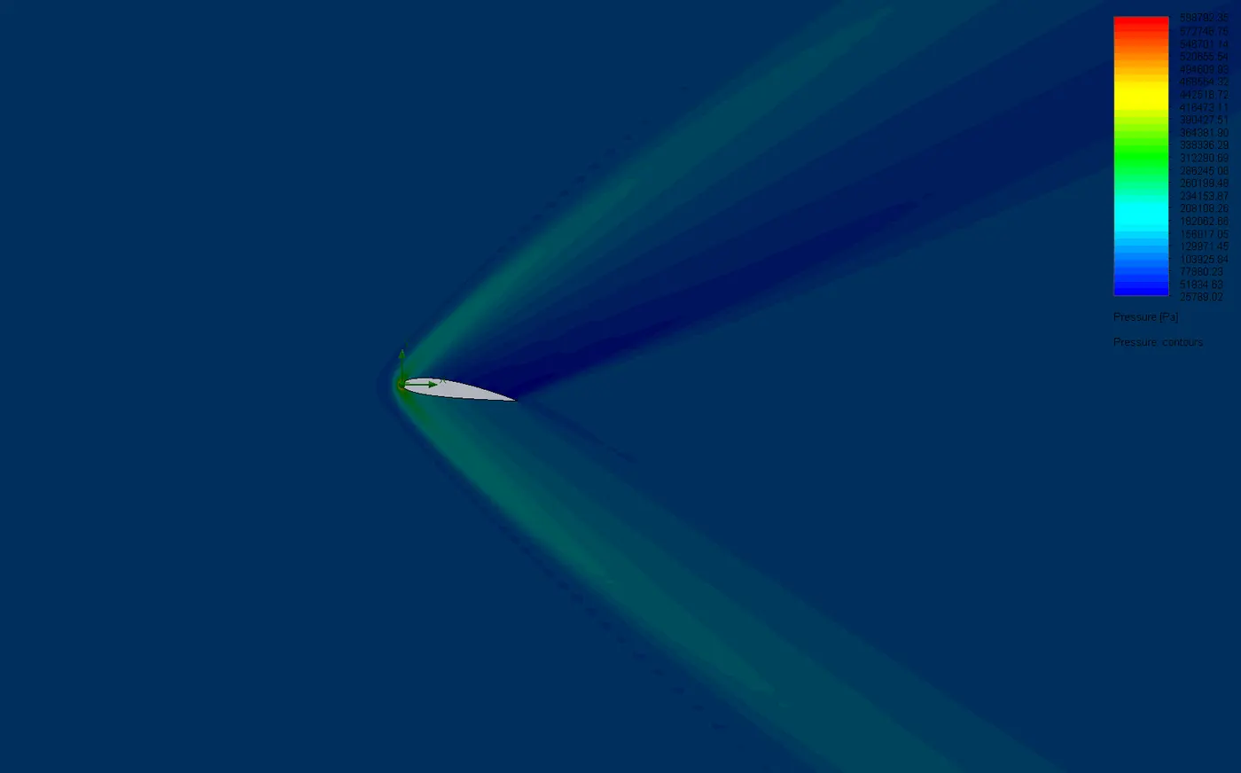
Case 5 : Angle of attack at `8^o`
| VELOCITY PLOT | PRESSURE PLOT |
 |
 |
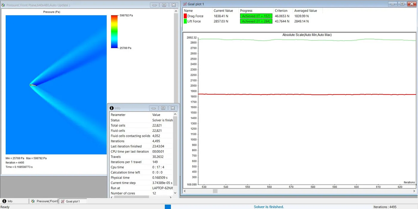
SIMULATION :
| DRAG FORCE | LIFT FORCE |
 |
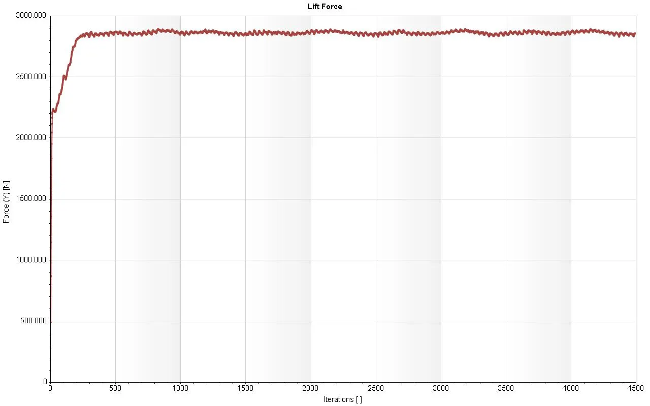 |
DRAG AND LIFT FORCE DATA :

Case 6 : Angle of attack at `10^o`
| VELOCITY PLOT | PRESSURE PLOT |
 |
 |
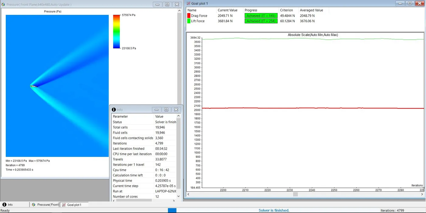
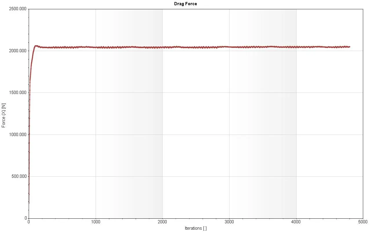
SIMULATION :
| DRAG FORCE | LIFT FORCE |
 |
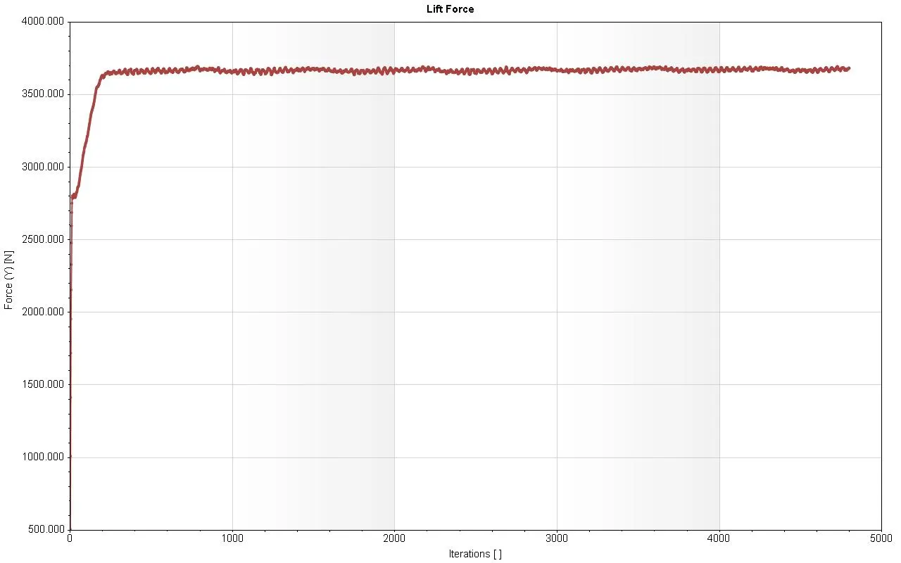 |
DRAG AND LIFT FORCE DATA :

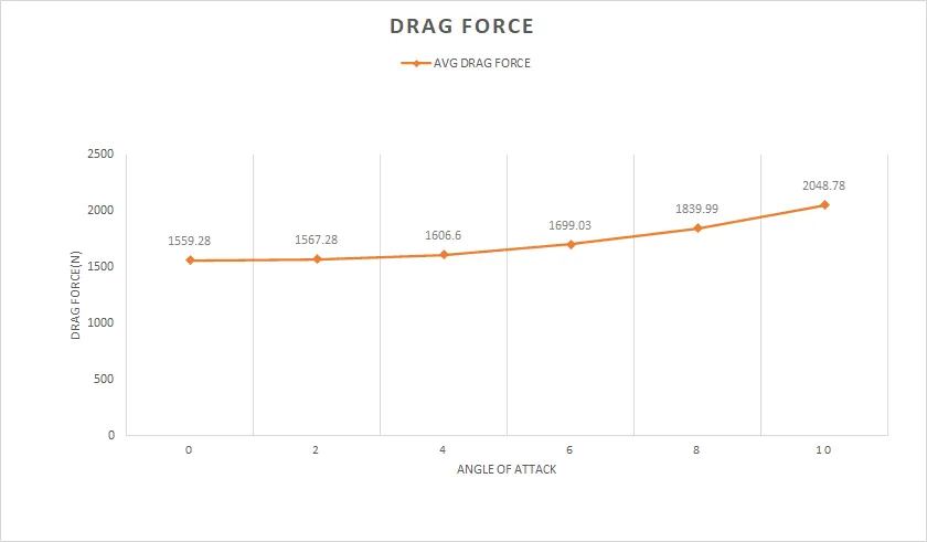
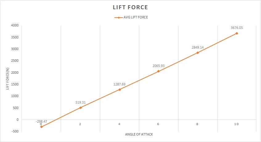
COMPARING LIFT AND DRAG FORCES :
 |
 |
CONCLUSION :
- The analysis of NACA-2415 airfoil has been carried out at various angles of attack and obtained the above result
- When the angle of attack is increased the lift on the surface also increases.
- When the angle of attack is at `0^o` the lift force is negative with a respective drag force.
- From the graph we can see that the lift force increases rapidly.
- With increase in angle of attack the velocity over the airfoil is increased which causes the low pressure region.