Modelling and simulation of flow through a flowbench
Modelling and simulation of flow through a flowbench
AIM :
Modelling and simulation of flow through a flowbench and do the following :
- Grid Dependency Test
- Effect of Valve lift on mass flow rate
INTRODUCTION :
An air flow bench is a device used for testing the internal aerodynamic qualities of an engine component and is related to the more familiar wind tunnel. It is used primarily for testing the intake and exhaust ports of cylinder heads of internal combustion engines. It is also used to test the flow capabilities of any component such as air filters, carburetors or manifolds thats is required to flow gas. A flow bench is one of the primary tools of high performance engine builders nad porting cylinder heads would be strictly hit or miss without it.
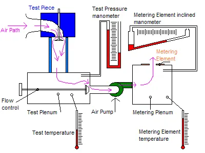
A flow bench consists of an air pump, metering element, pressure and temperature measuring instruments such as manometers and various comtrols. The test piece is attached in series with the pump and measuring element and air is pumped through the whole system. The mass flow rate can be calculated using the known pressure and temperature data to calculate air densities and multiplying by the volume flow rate.
PROCEDURE :
- Create a flow bench model with the required dimensions and constraint these dimensions.
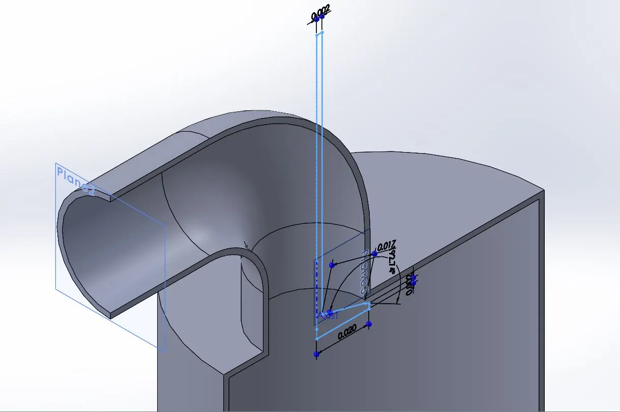
- The valve is opened at Valve Lift = 0.002m
- Run the wizard with internal flow type and fluid as AIR
- Boundary Conditions :
Total Pressure at intake = 501325`Pa`
Static Pressure at exit = 101325`Pa` - Goals :
Surface goal for calculation of mass flow rate at the exit - Set the Global mesh grid size : 5 Level
Create a Local mesh along the valve surface : Refined to 4 Level.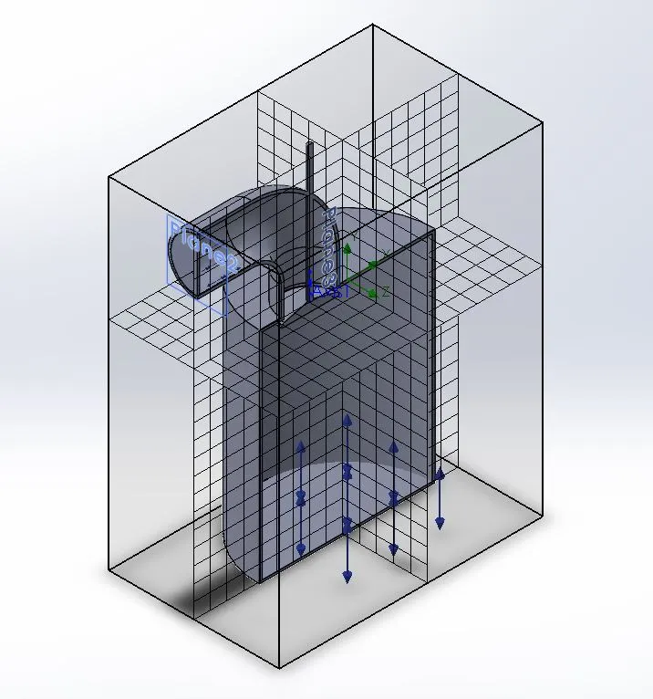
- Cut plots for velocity and pressure, Flow trajectory plot of velocity and Goal plot are inserted to observe the result.
- The basic simulation is run.
Grid Dependency Test :
- Parametric study is started with global mesh size as the input parameters and values 5,6,7 are give as input.
- Cut plots of velocity and pressure, Goal plot of mass flow rate and Velocity flow trajectory are the output parameters.
Effect of Valve lift on Mass flow rate :
- Parametric study is started with Valve open distance as the input parameter
- Cut plots of Velocity and pressure, Goal plot of mass flow rate and Velocity flow trajectory are the output parameters.
RESULT :
GRID DEPENDENCY TEST WITH VALVE LENGTH = 0.002m
| MESH SIZE | VELOCITY PLOT | PRESSURE PLOT |
| 5 | 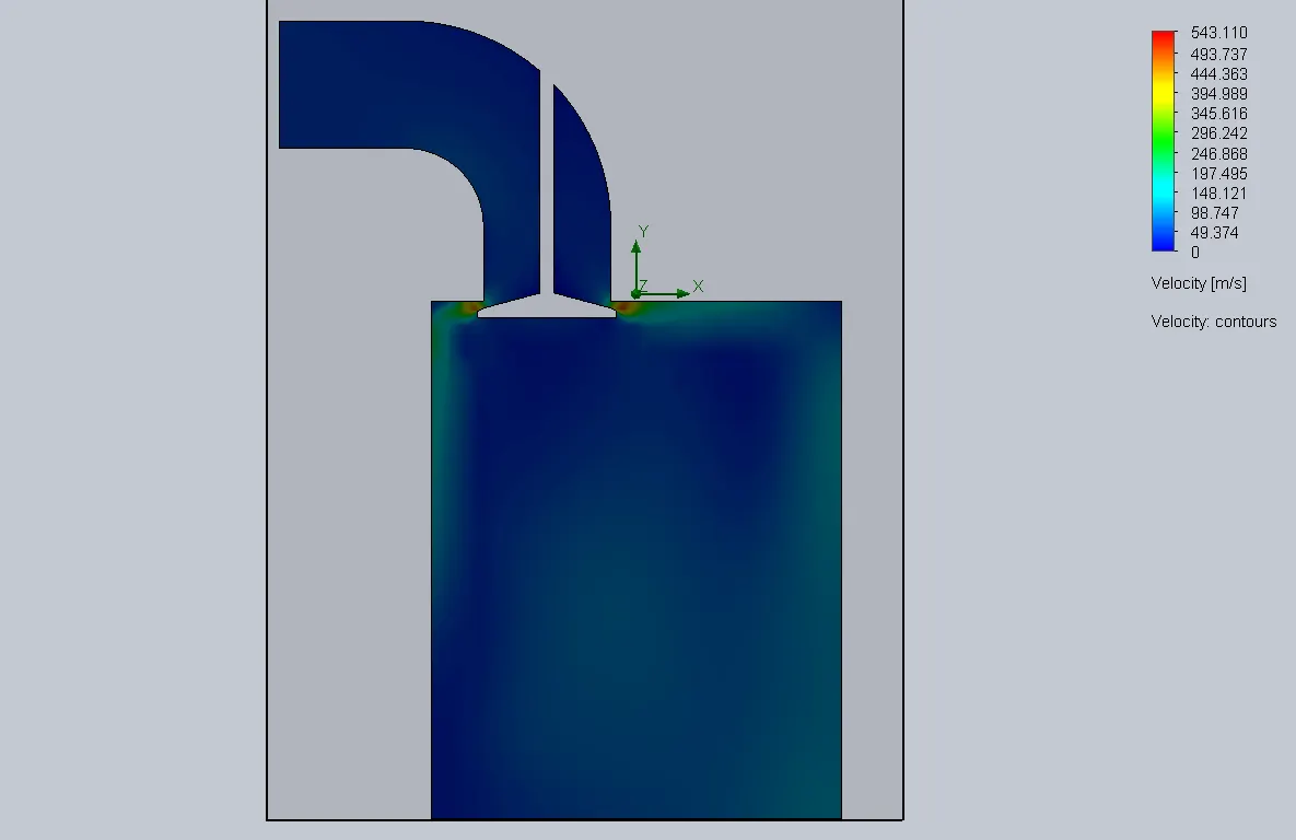 |
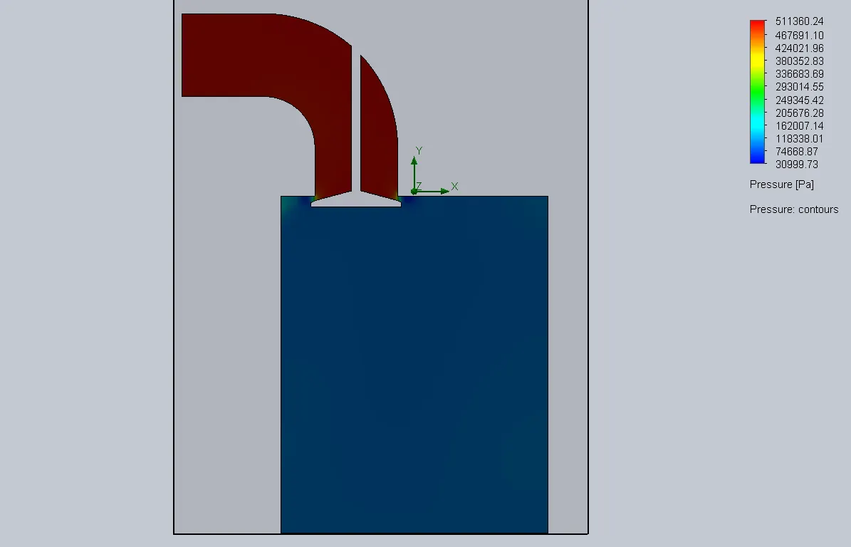 |
| 6 | 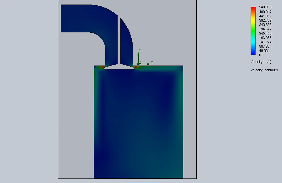 |
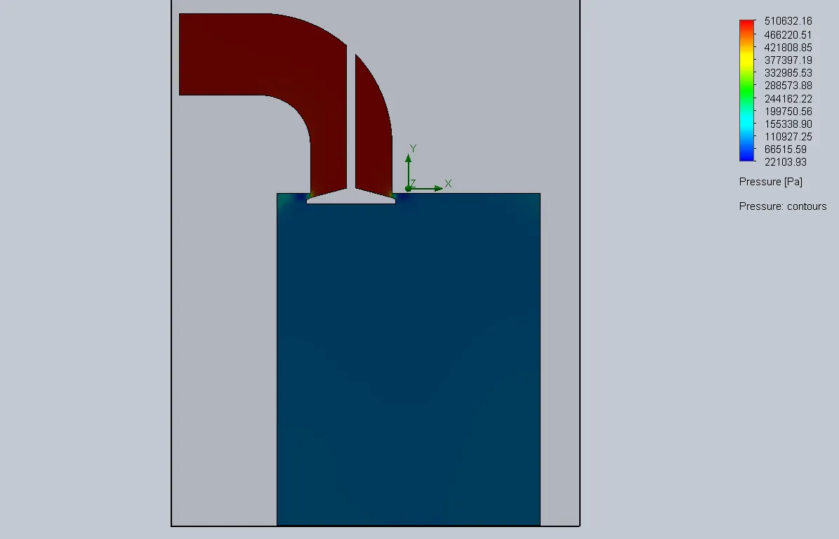 |
| 7 | 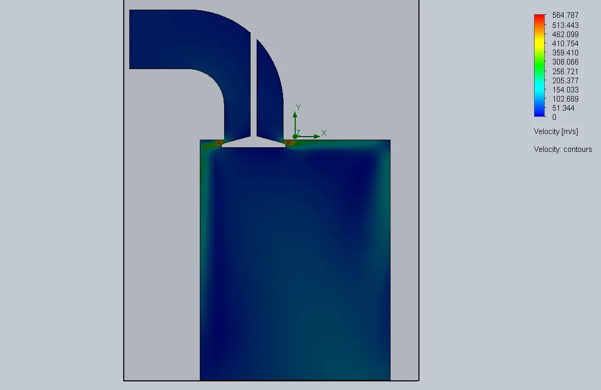 |
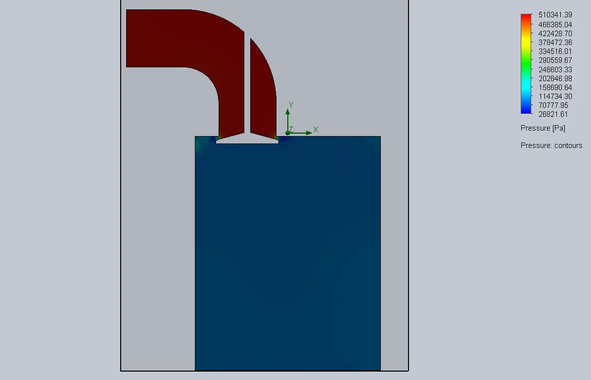 |
TRAJECTORY PLOT :
| MESH SIZE | VELOCITY TRAJECTORY PLOT |
| 5 | 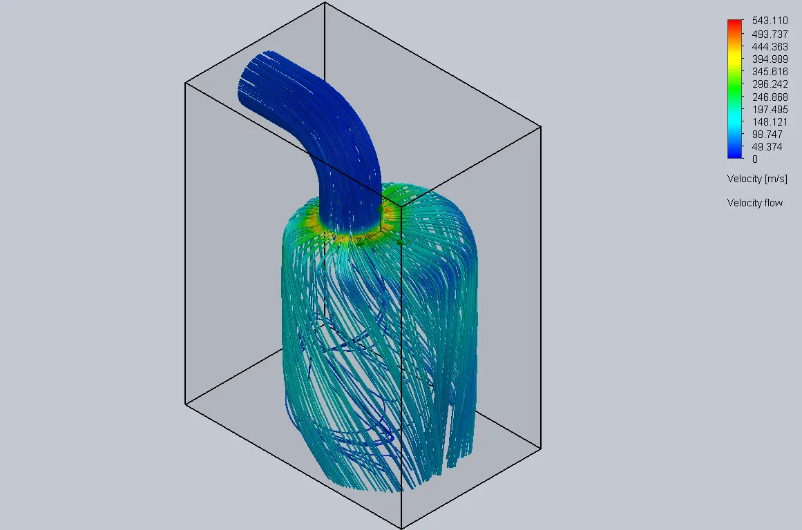 |
| 6 | 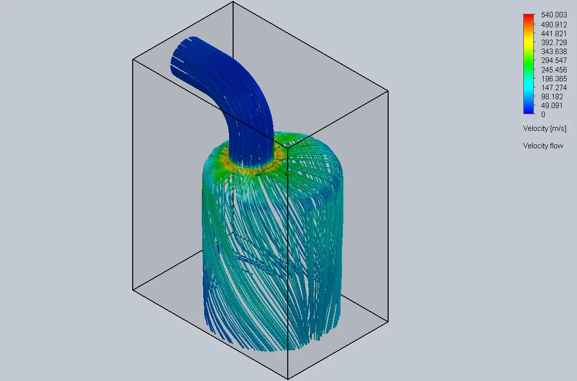 |
| 7 | 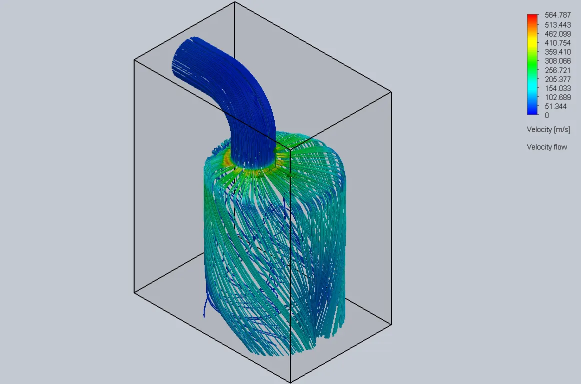 |
MESH SIZE VS MASS FLOW RATE :

Effect of Valve lift(Mesh= Level 6) :
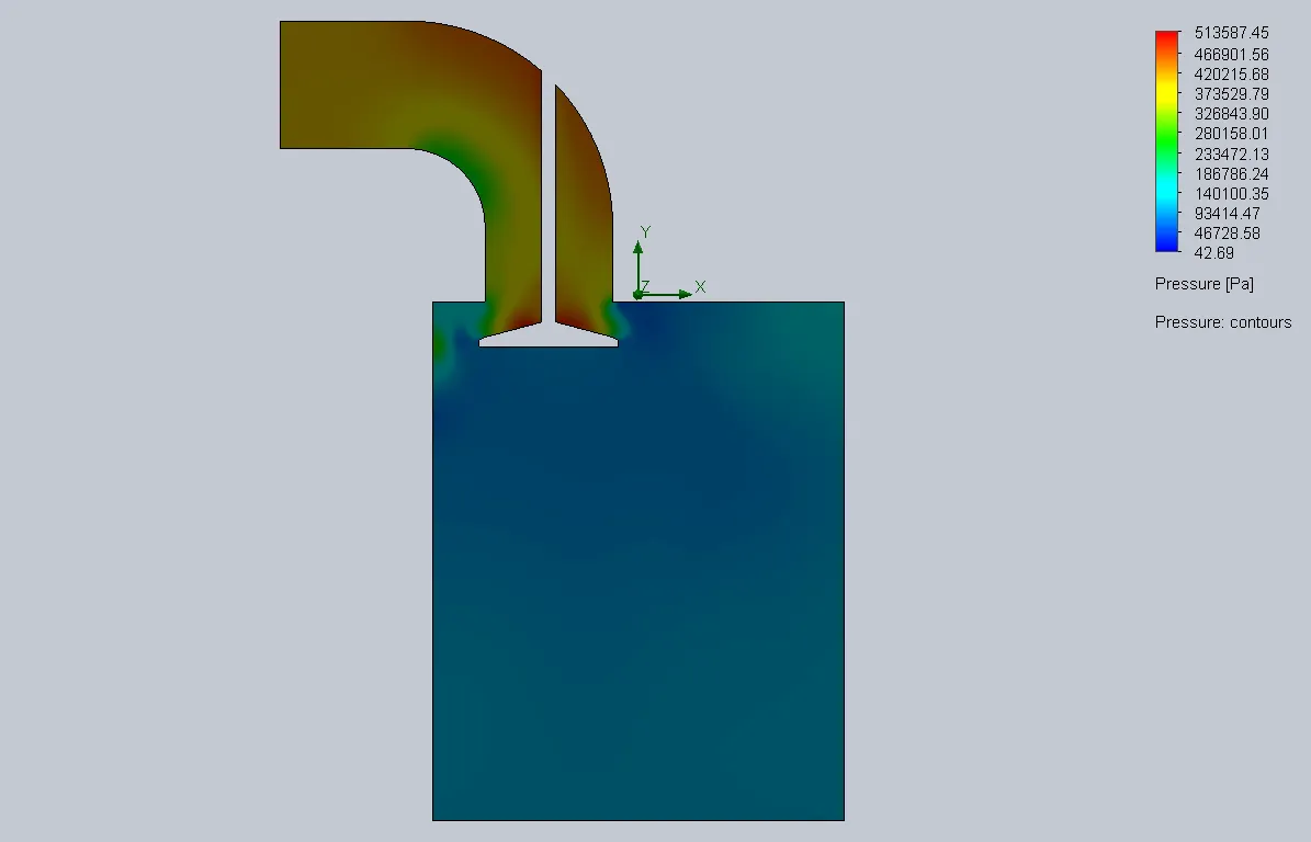
| VALVE LIFT | VELOCITY PLOT | PRESSURE PLOT |
| 0.002m | 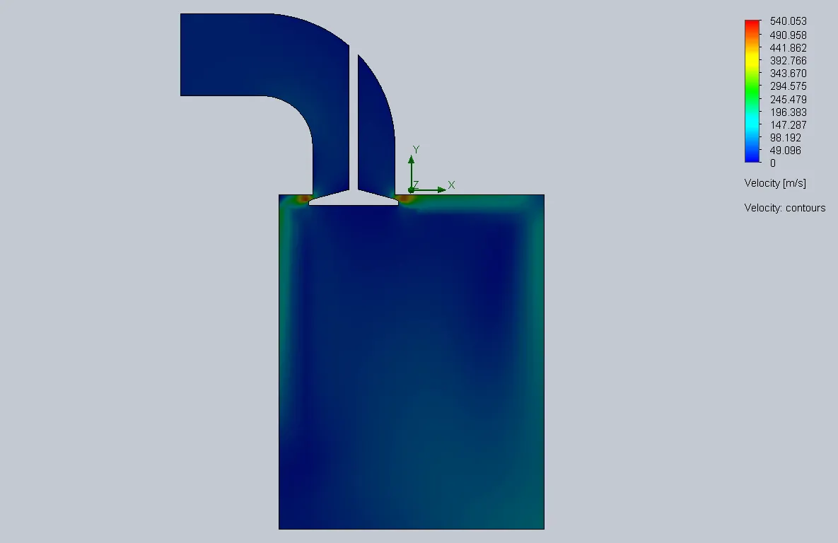 |
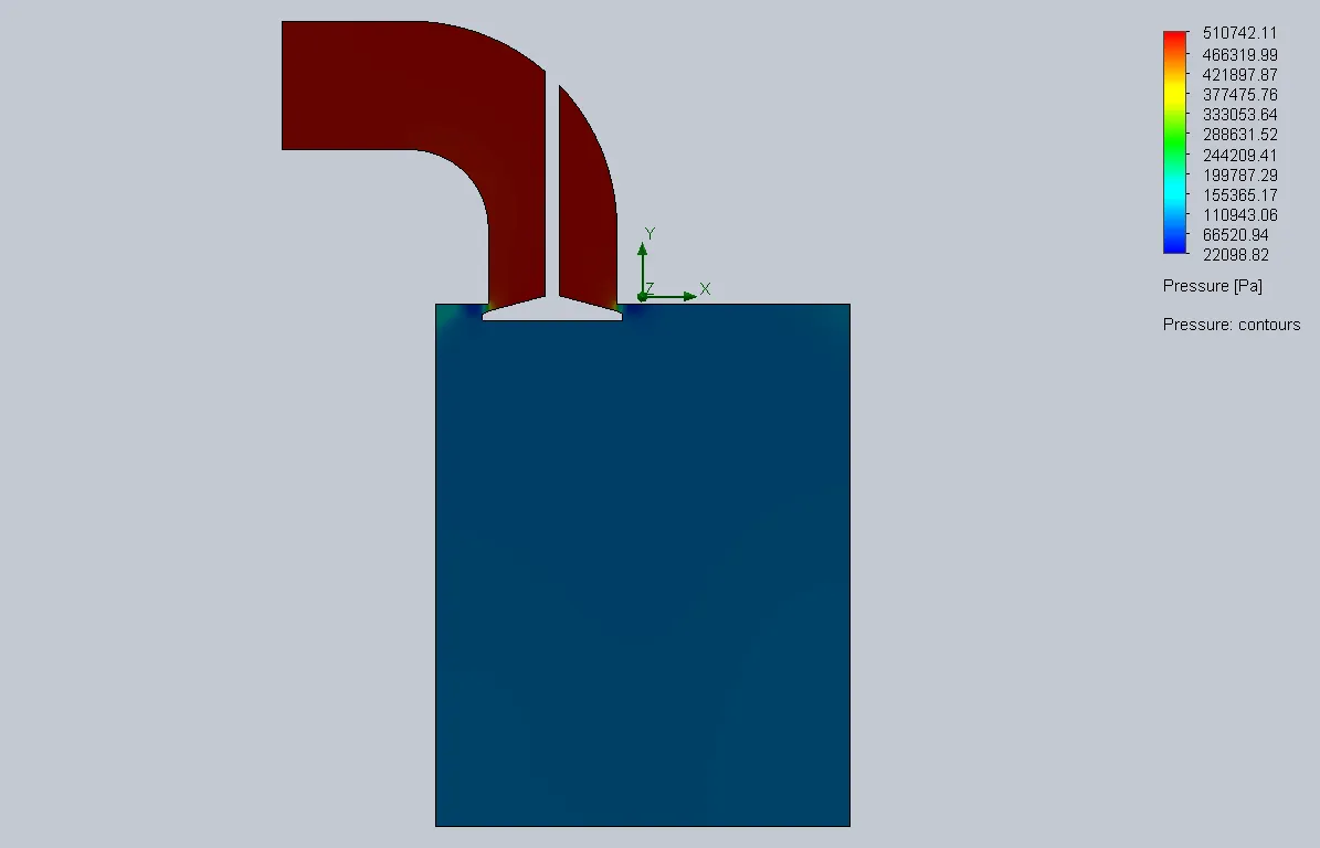 |
| 0.004m | 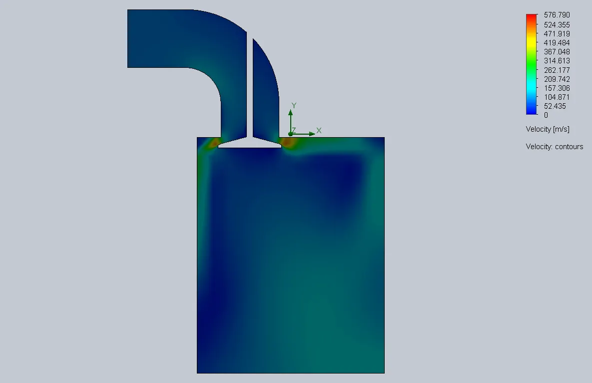 |
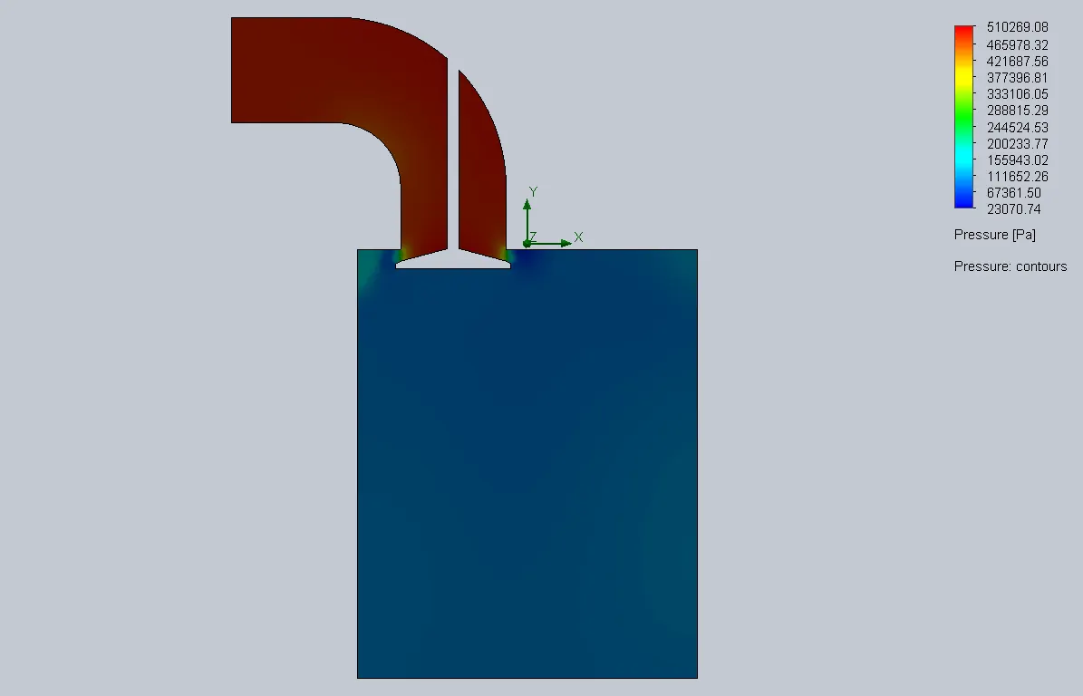 |
| 0.006m | 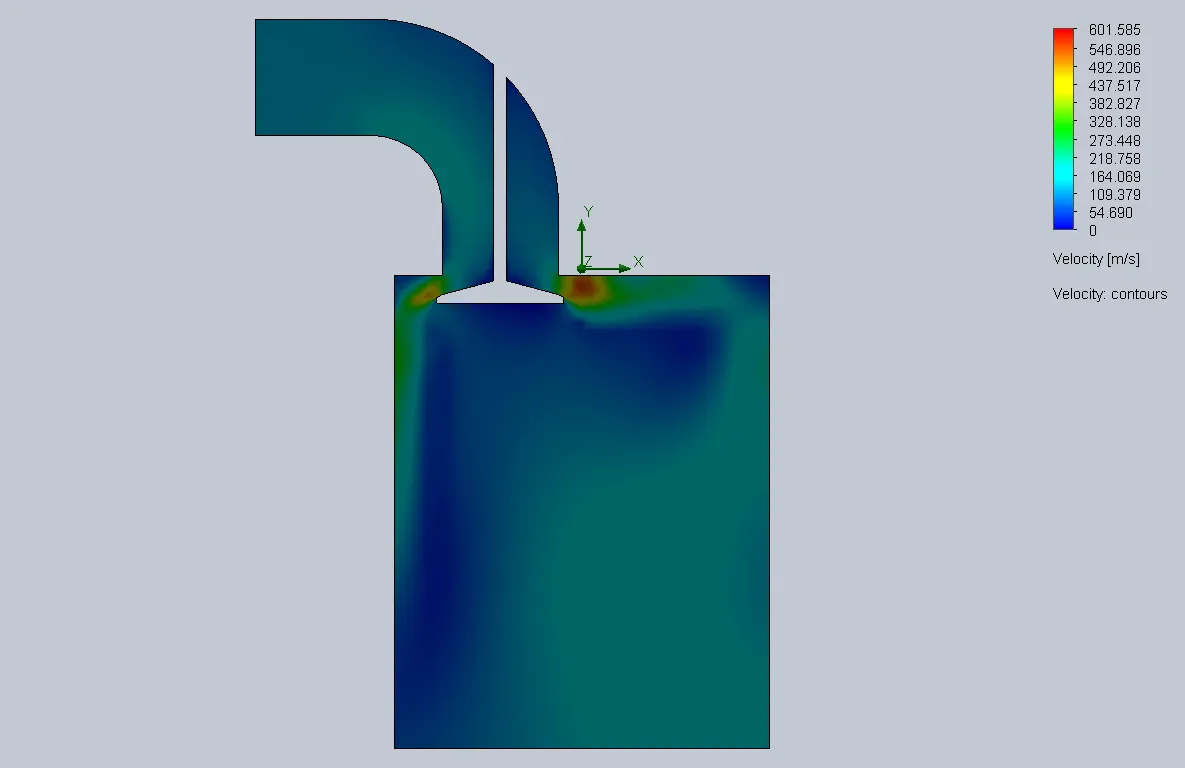 |
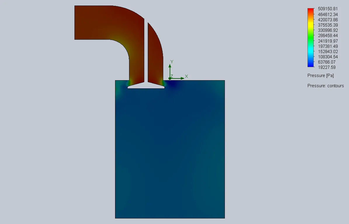 |
| 0.008m | 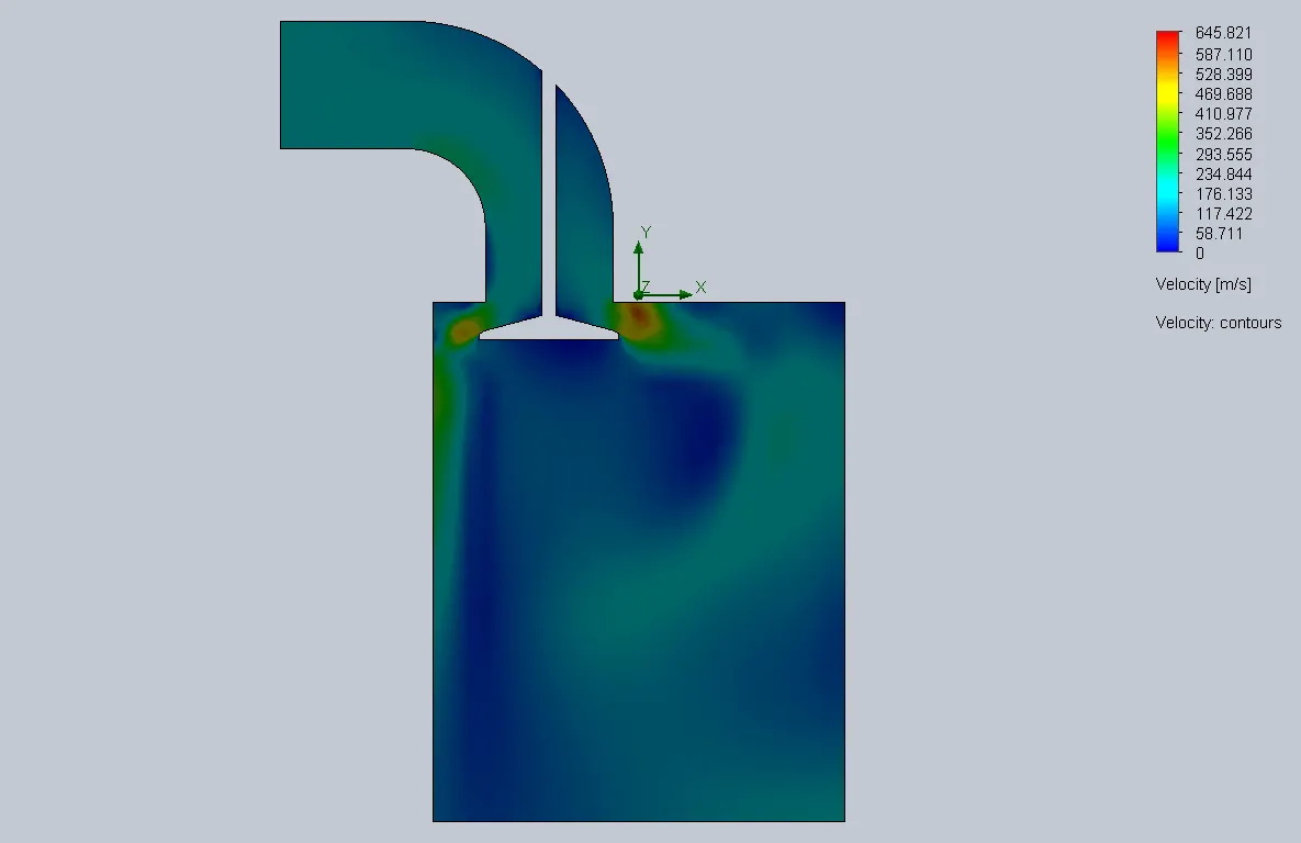 |
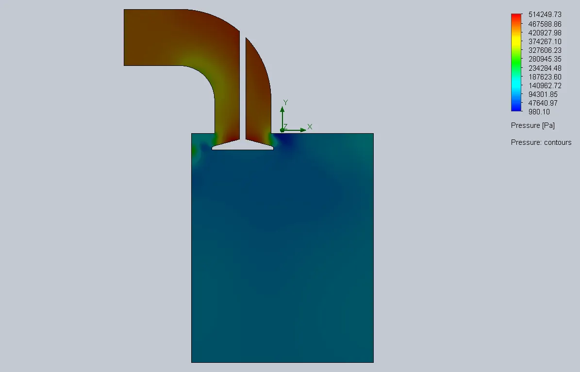 |
| 0.01m | 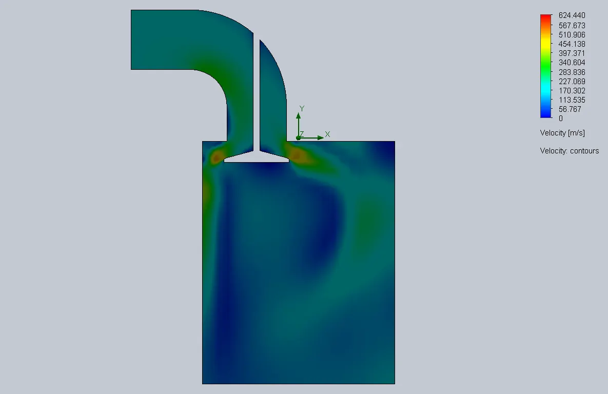 |
 |
TRAJECTORY PLOT :
| VALVE LIFT | VELOCITY TRAJECTORY PLOT |
| 0.002m | 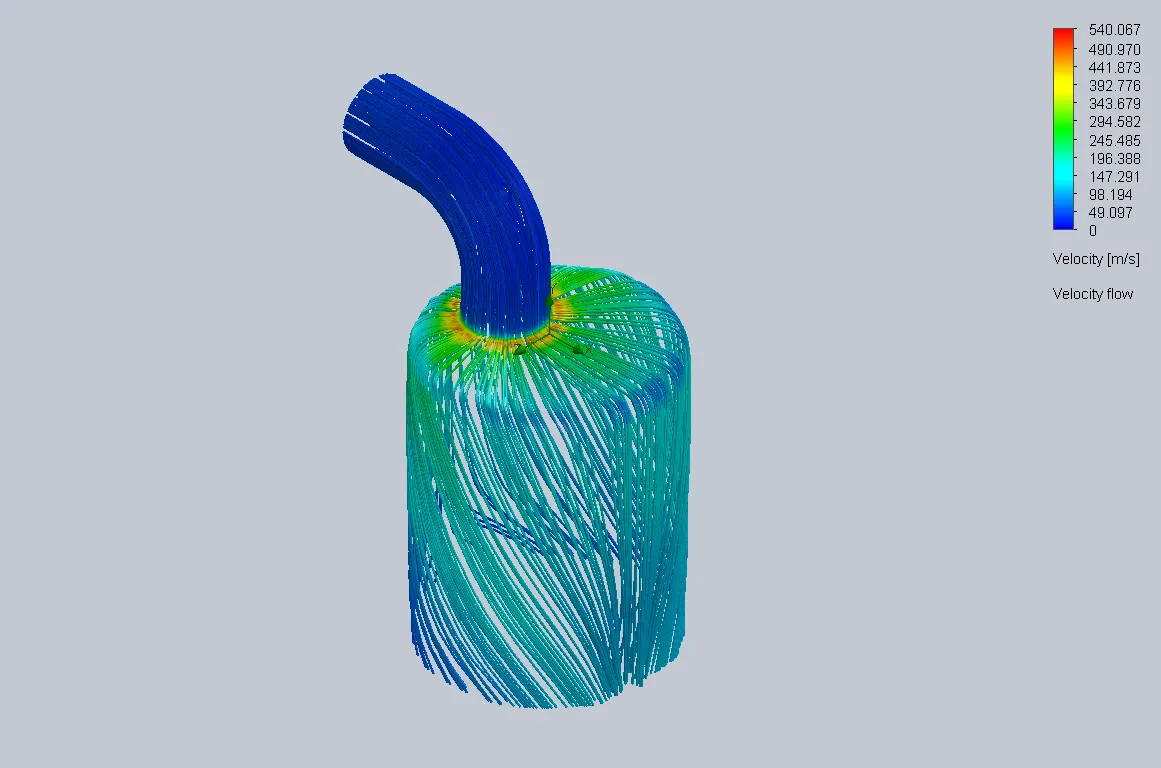 |
| 0.004m | 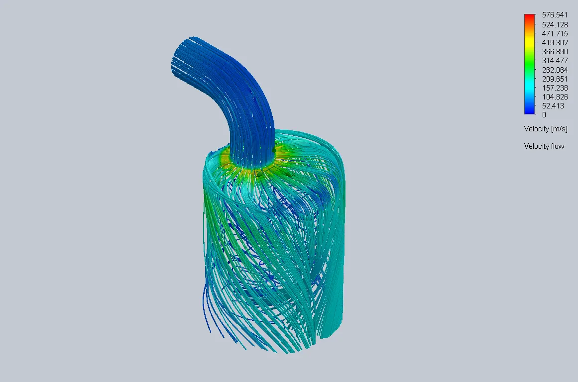 |
| 0.006m | 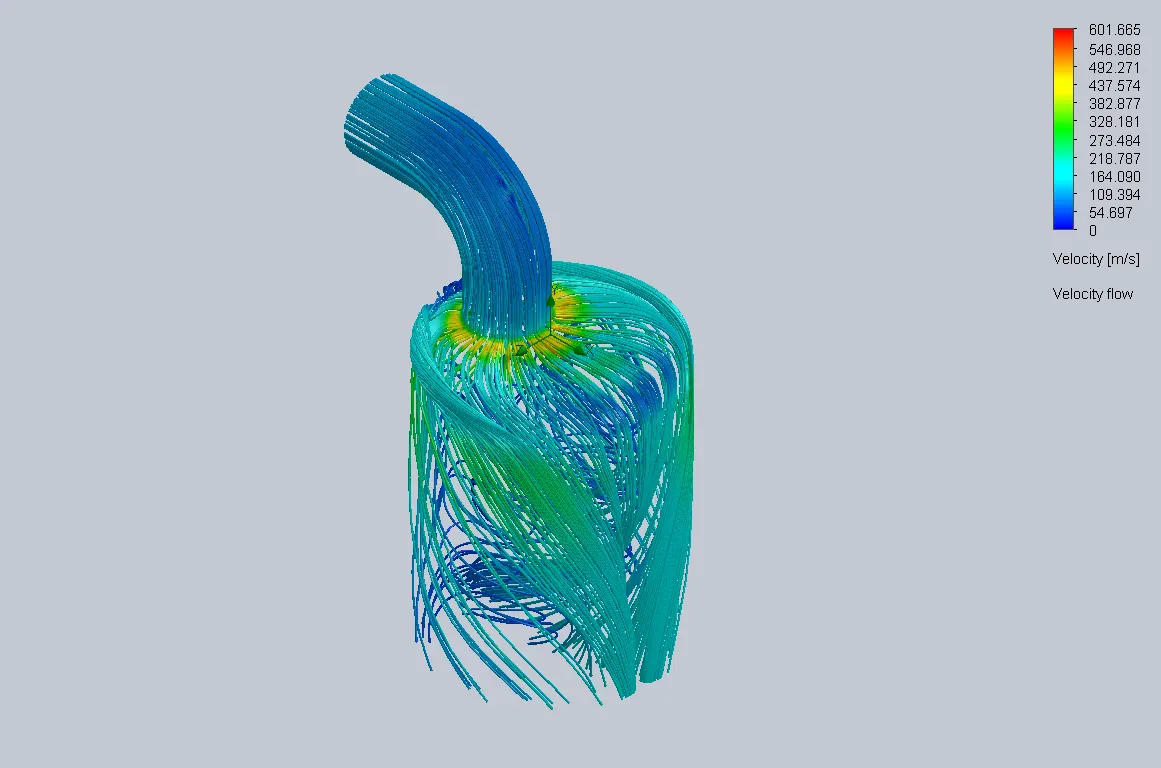 |
| 0.008m | 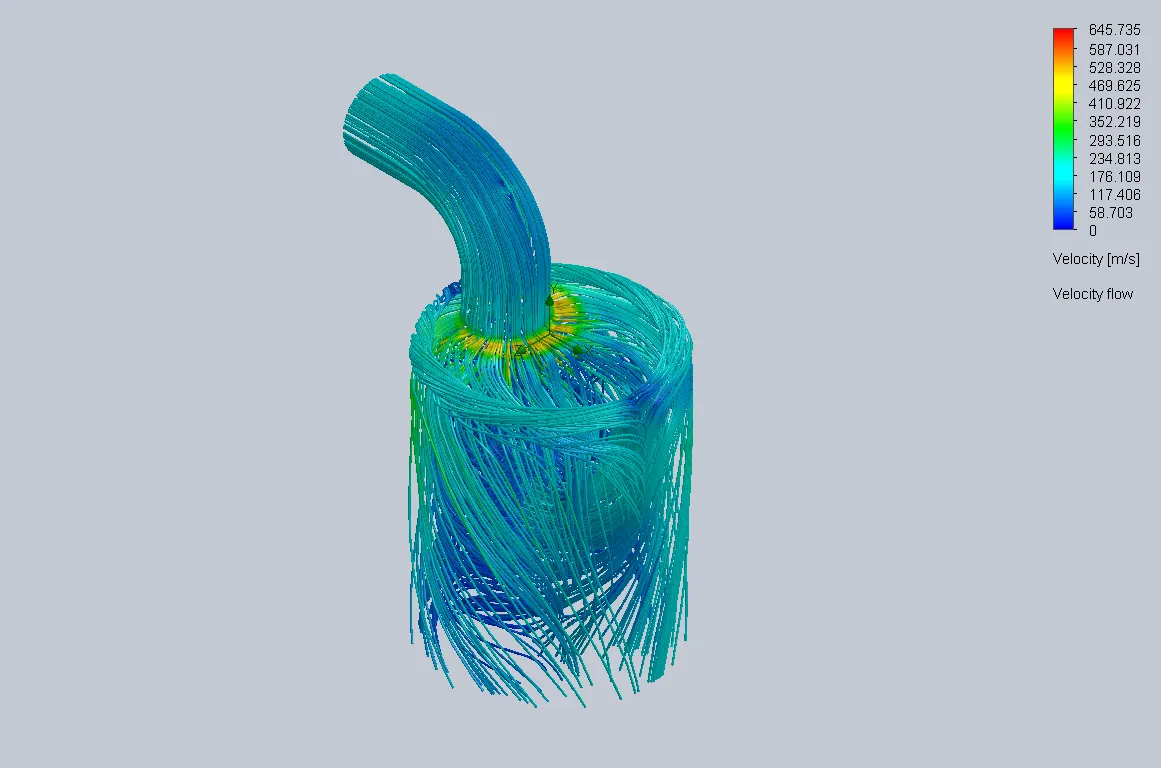 |
| 0.01m | 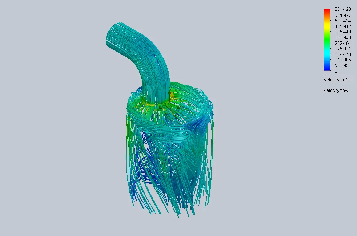 |
VALVE LENGTH VS MASS FLOW RATE :
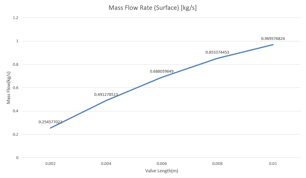
CONCLUSION :
Pressure, velocity and mass flow rate are the important parameters which needs to be considered while designing a flow bench test. This simulation helps us understand what occurs in the suction stroke of an engine. More level of global mesh helps us to obtain more accurate results.