Week 7 Challenge - Assembly Workbench
Assembly Workbench
AIM :
To understand the basic concept and assemble the part with respective relation of the part and constrain with respective object in Catia V5
OBJECTIVE :
1) To create the various individual part models from the 2D drawings provided.
- Quick return mechanism
- CV joint
2) To assemble the part models into a single component.
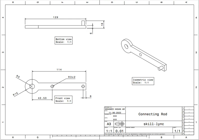
3) To create the 2D drawings of the components which were created.
SKETCH & PART WORKBENCH:
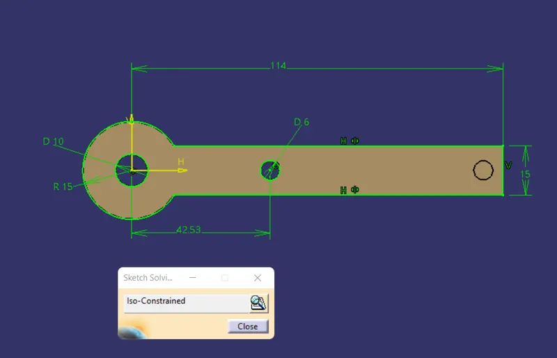
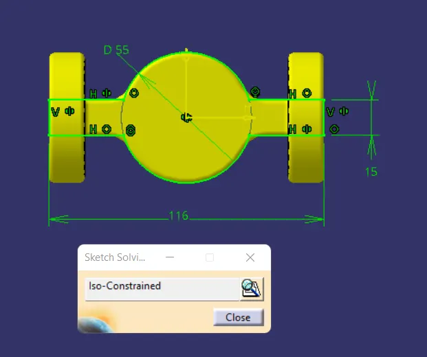
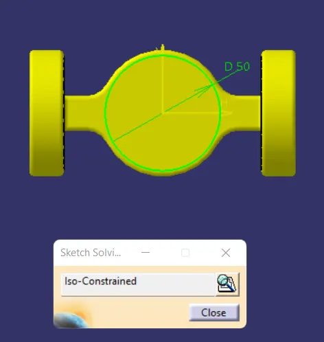
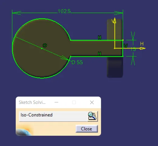
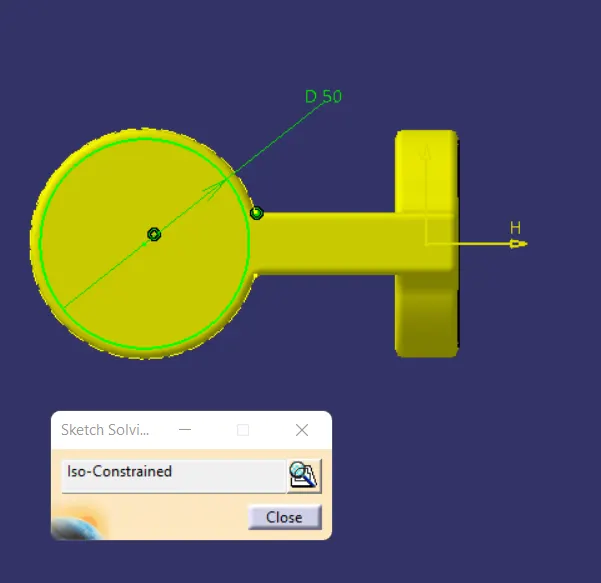
1) Create a all sketch by using positioned sketch command
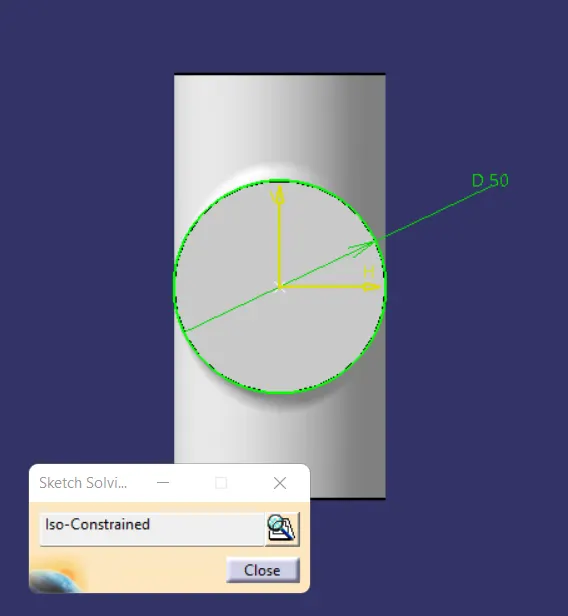
2) Ensure that all the sketches in iso- constrained
3) Use pad command for thicken solid for all sketch
4) bring the desire profile using Boolean Operation.
A) QUICK RETURN MECHANISM:
- ASSEMBLY PART
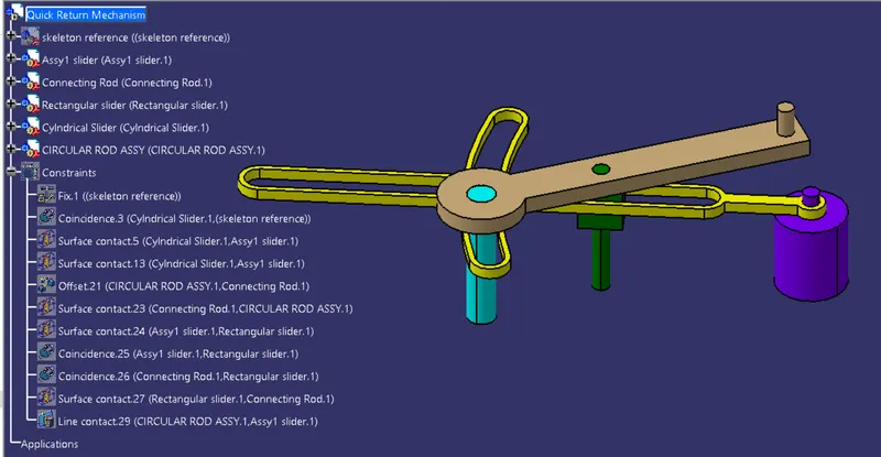
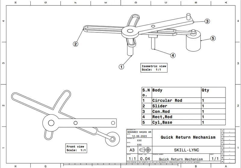
INDIVIDUAL PARTS
- SLIDER
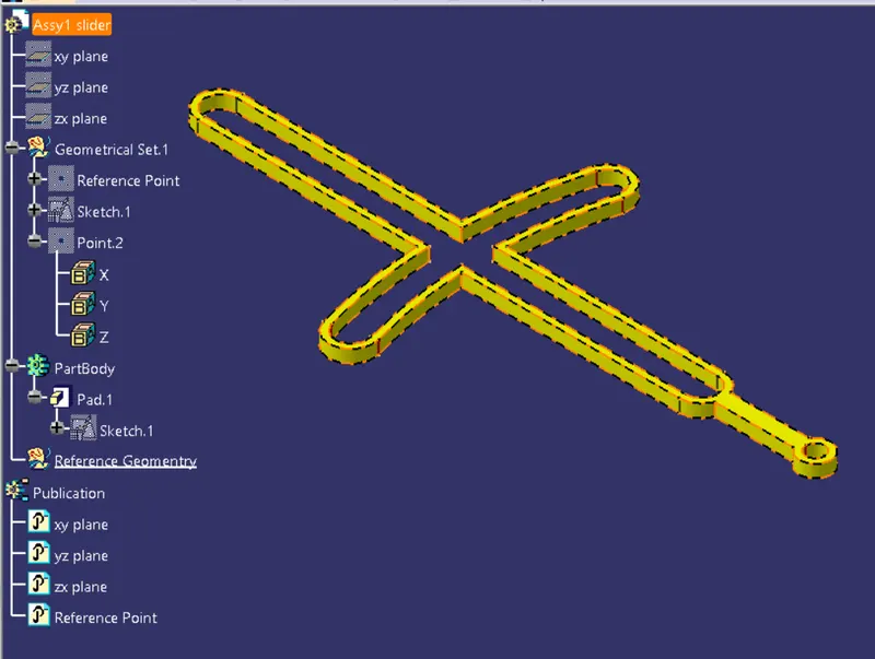
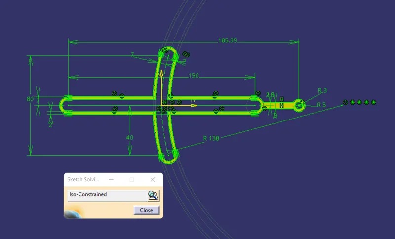
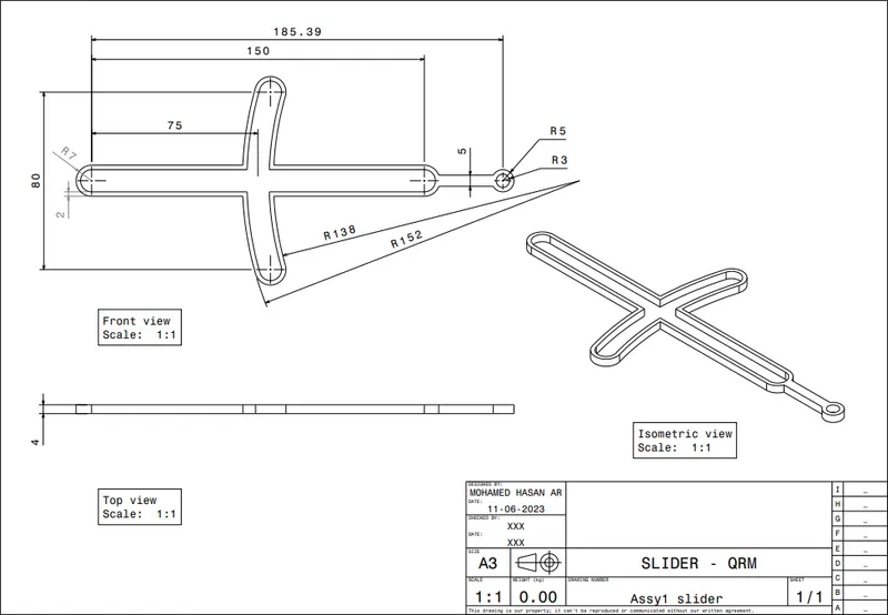
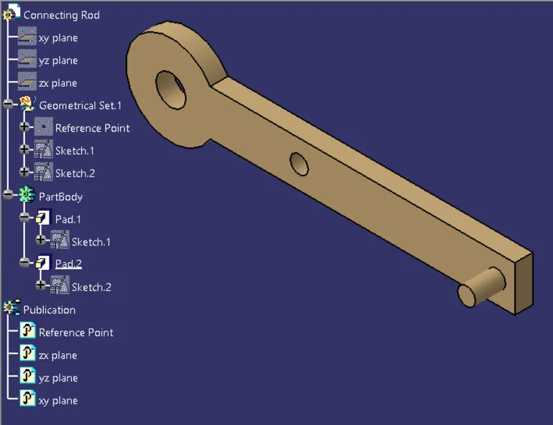
- CON.ROD
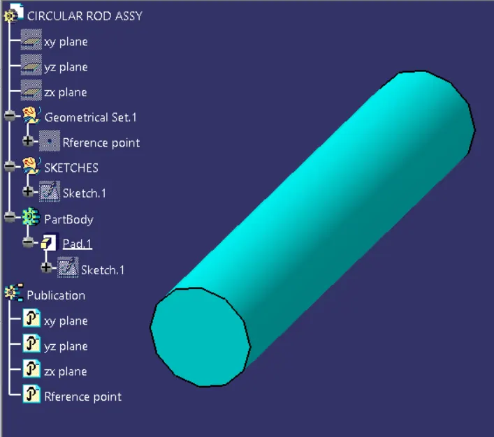
- CIR.ROD
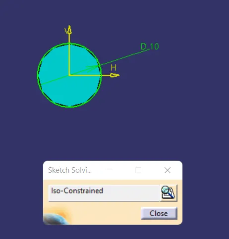
- CYL.BASE
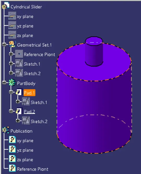
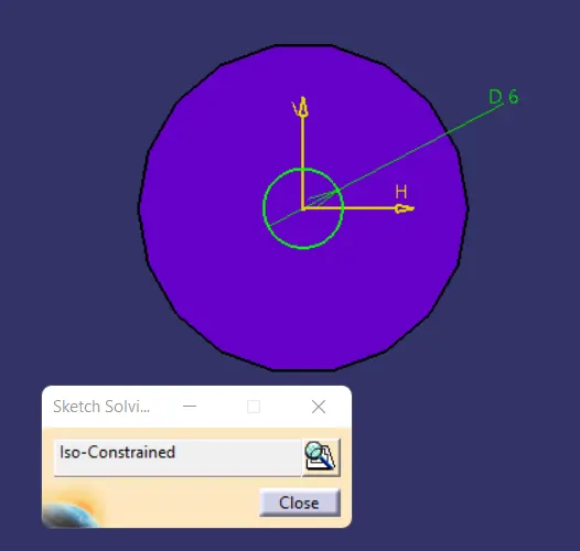
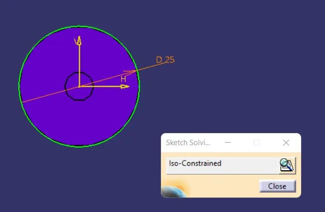
- RECT.SLIDER
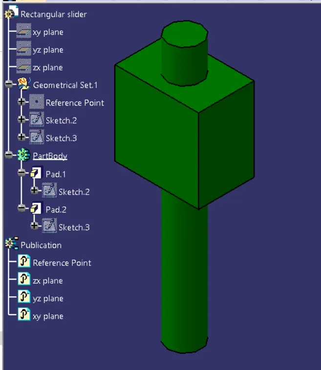
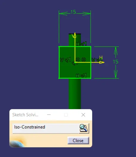
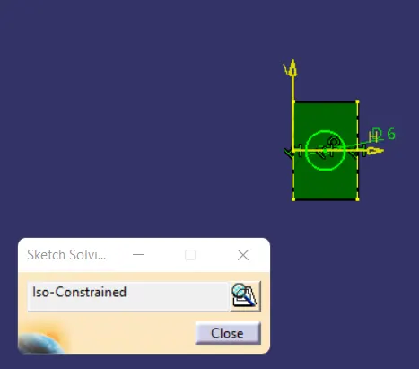
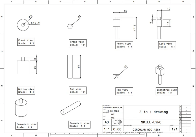
B) CV JOINT
ASSEMBLY PART
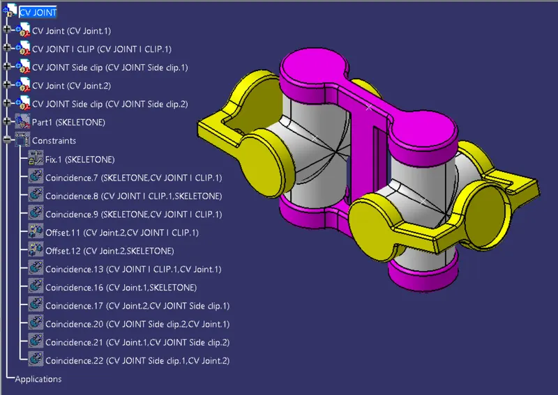
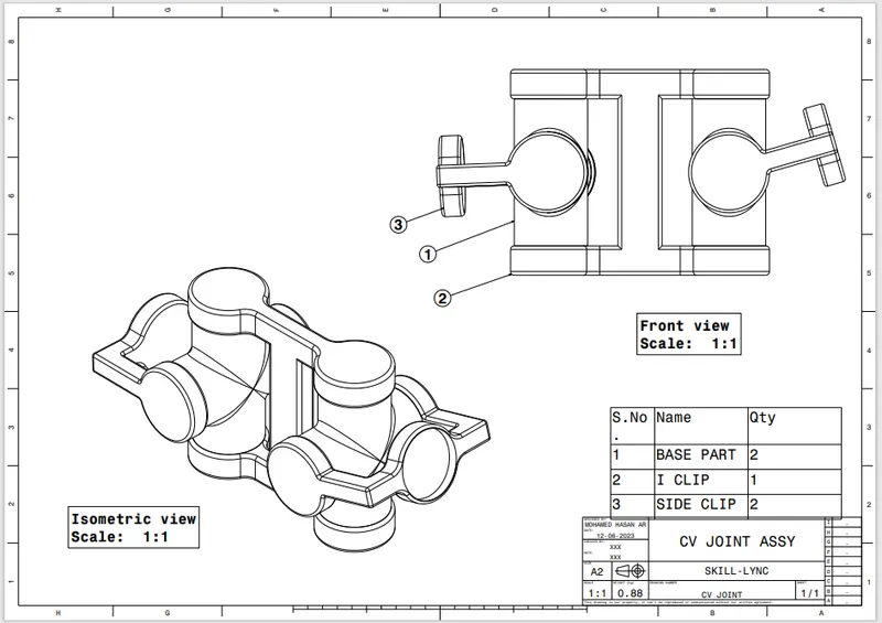
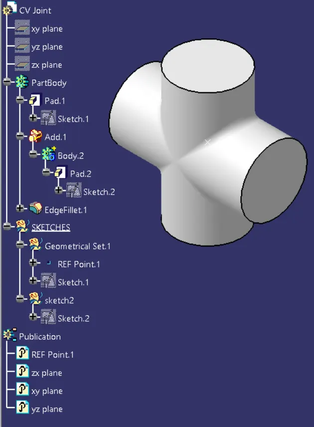
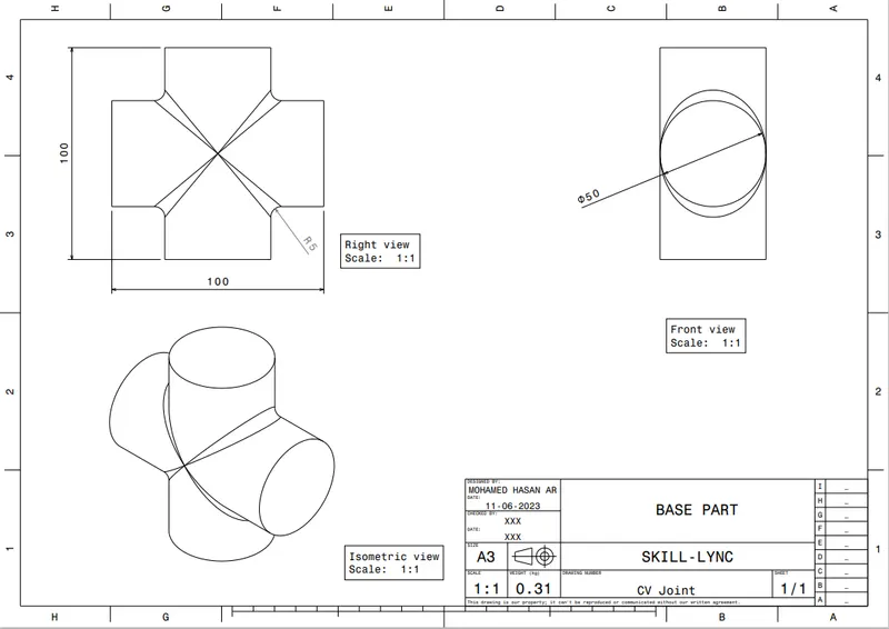
- BASE PART
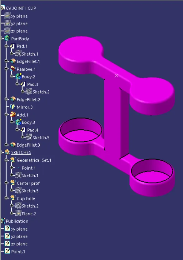
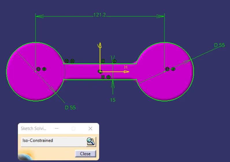
- I CLIP
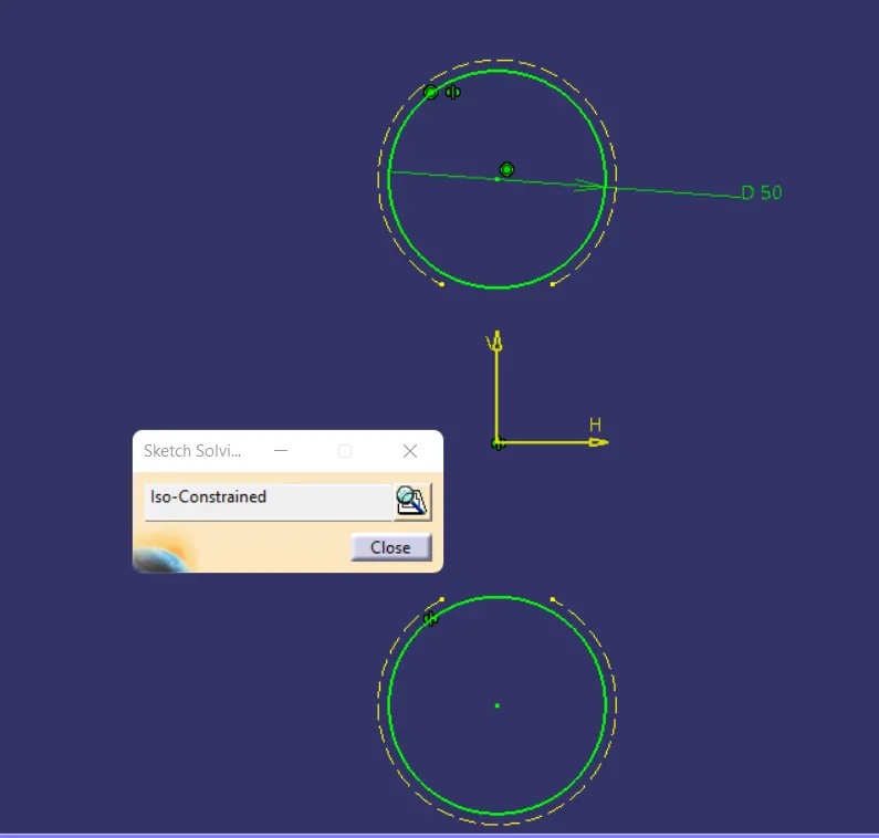
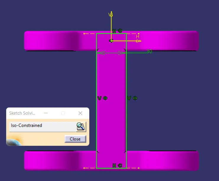
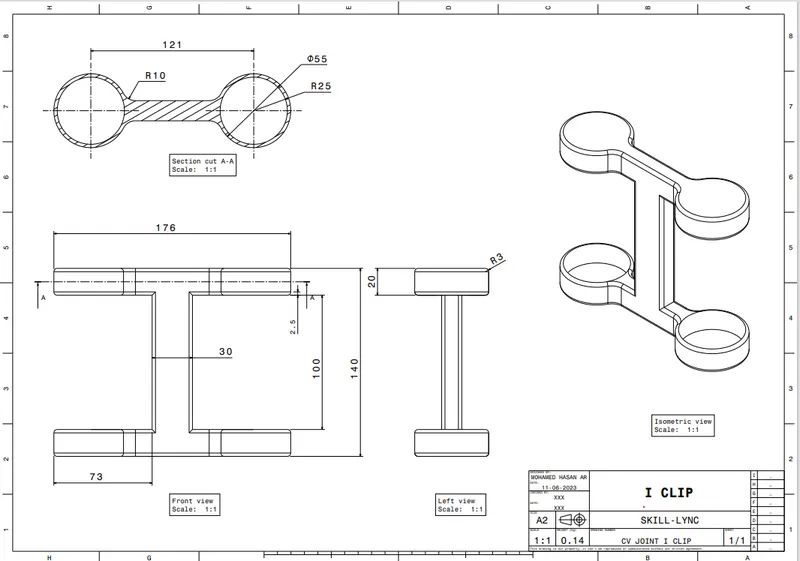
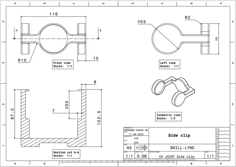
- SIDE CLIP
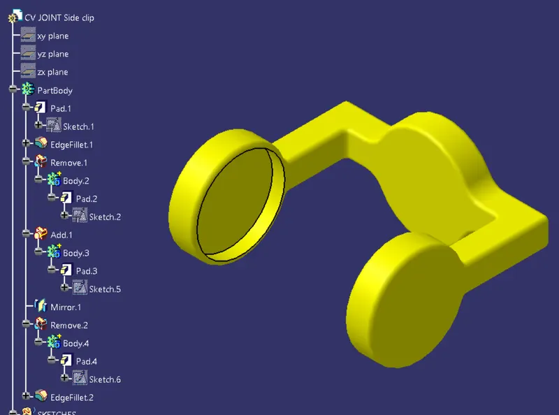
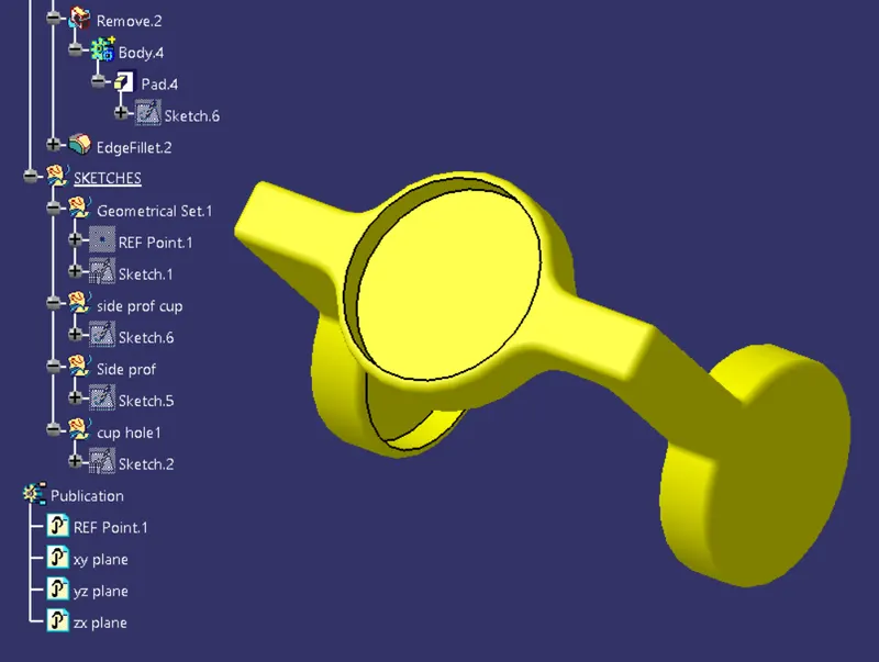
ASSEMBLY WORKBENCH :
1) Create a new CATproduct and insert all the above separate CATPART by using existing component command.
2) Create a reference elements for all catparts
3) Add Reference elements like axis, points wherever we need
4) Use publication tool to make all the necessary elements like planes,points,axis to make visible.
5) Make the reference part fixed.
6) After placing the components in the product file, you need to assemble them. By assembling the components, you will constrain the degree of freedom of the components. the components are assembled using the constraints. Constraints help you to precisely place and position the components with respect to the other components and the surroundings in the assembly. If all degrees of freedom of all components of the assembly are restricted, it is called a fully constrained assembly. Else it is called a partially constrained assembly. If some mechanism needs to be created after assembling the components, some degrees of freedom of the assembly needs to be kept free intentionally, so that movements can be achieved in that direction. Various types of constraints available in CATIA are discussed below.
- Contact Constraint :
The Contact Constraint is applied to make a surface to surface contact between two selected elements from two different components. The elements to be selected can be planes, planar faces, cylindrical faces, spherical faces, conic faces, or circular edges. To invoke this tool, choose the Contact Constraint button from the Constraints toolbar. you are prompted to select the first geometric element of the Contact constraint. Select the element from the first component. Next, you are prompted to select the geometric element to place in contact with the first selection. Select the element from the second component. A Contact constraint will be applied between the two elements and the component will be placed with respect to the constraints after updating. The Contact constraint symbol will be displayed on the assembled components.
- Fix Together :
The Fix Together constraint is used to fix the position of the selected components with respect to each other. Once the selected components are fixed together, they can be moved as a single component such that the position of one component with respect to another component remains the same. To invoke this tool, choose the Fix Together button from the Constraints toolbar; the Fix Together dialog box is displayed. Now, select components to be linked. The part number of the selected components are displayed in the Fix Together dialog box. If you want to remove a particular component from the list, click on its part number in the Components selection area. Choose the OK button from the Fix Together dialog box to apply the Fix Together constraint.
- Moving and Rotating Using the Manipulation Tool
The Manipulation tool is used to move or rotate the component freely by dragging
the cursor. To translate or rotate any component, choose the Manipulation button
from the Move toolbar.
- Offset Constraint
The Offset Constraint is used to place selected elements at an offset distance from
each other. It also makes the two planar faces parallel to each other. To invoke this
tool, choose the Offset Constraint button from the Constraints toolbar. After invoking the tool you are prompted to select the first geometric element for the Offset constraint.
Select a planar face, circular face, plane, axis, or a point from the geometry area. You are prompted to select the second geometric element. Select a planar face of another component. Then enter the values based on that we can maintain the distance between both geometric elements.
CONCLUSION :
The part components and their respective assemblies were created.
The 2D drawings of the components were created.
Necessary files and images were attached.
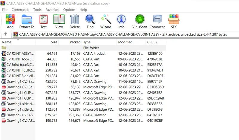
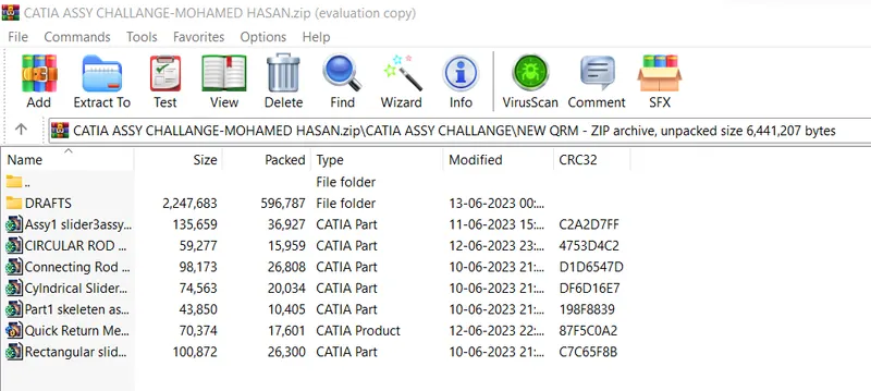
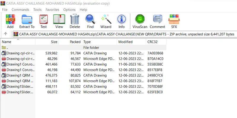
NOTE : All part models(.CATPart), assembly file (.CATProduct), drawing files & pdf are attached in a single ZIP file folder.