DESIGN OF AN AMERICAN PREDATOR YACHT
DESIGN OF AN AMERICAN PREDATOR YACHT
Aim:
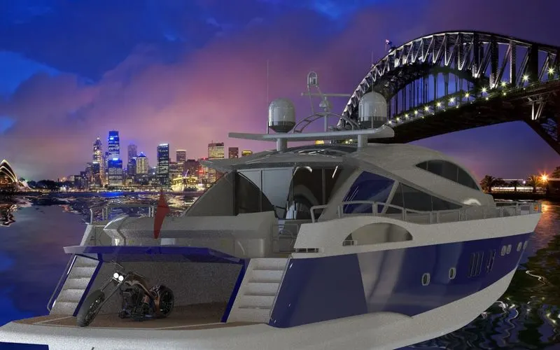
To sketch and modelling a different parts of an American Predator Yacht, Assemble them together, apply decals and rendering the model by photoview 360 in SOLIDWORKS and Photo-realistic rendering using Solidworks Visualize
OBJECTIVE:
• The objective of the project is to design and model all the individual components of an American Predator Yacht with the help of blue prints and assembling the entire model together to form a good aesthetical yacht by Solidworks.
• And to create the Photo-Realistic rendering of the yacht by using a SOLIDWORKS VISUALIZE.
• The main purpose of project is To Learn and apply different tools of surface modeling, understand the all commands in depth that we use in this to create a full yacht
INTRODUCTION:
• Solidworks software is a mechanical cad software which helps the designers to show their idea of a part or model in a realistic view in a virtual representation without actually producing a real part,which is so helpful to make corrections or to make new changes in the model easily before making a physical part product.
• In this project, the American Predator Yacht was taken as a conceptual model, to understand the 3D modelling methodology of Solid modelling and Surface modelling. Each and every part of the yacht was designed and modelled using SOLIDWORKS. Then the modelled parts were assembled by adding proper mates and constraints to create the Photo-Realistic rendered image of the Yacht
• Here almost 90% of the model is modelled using surface modelling and the we make them into a solid body.
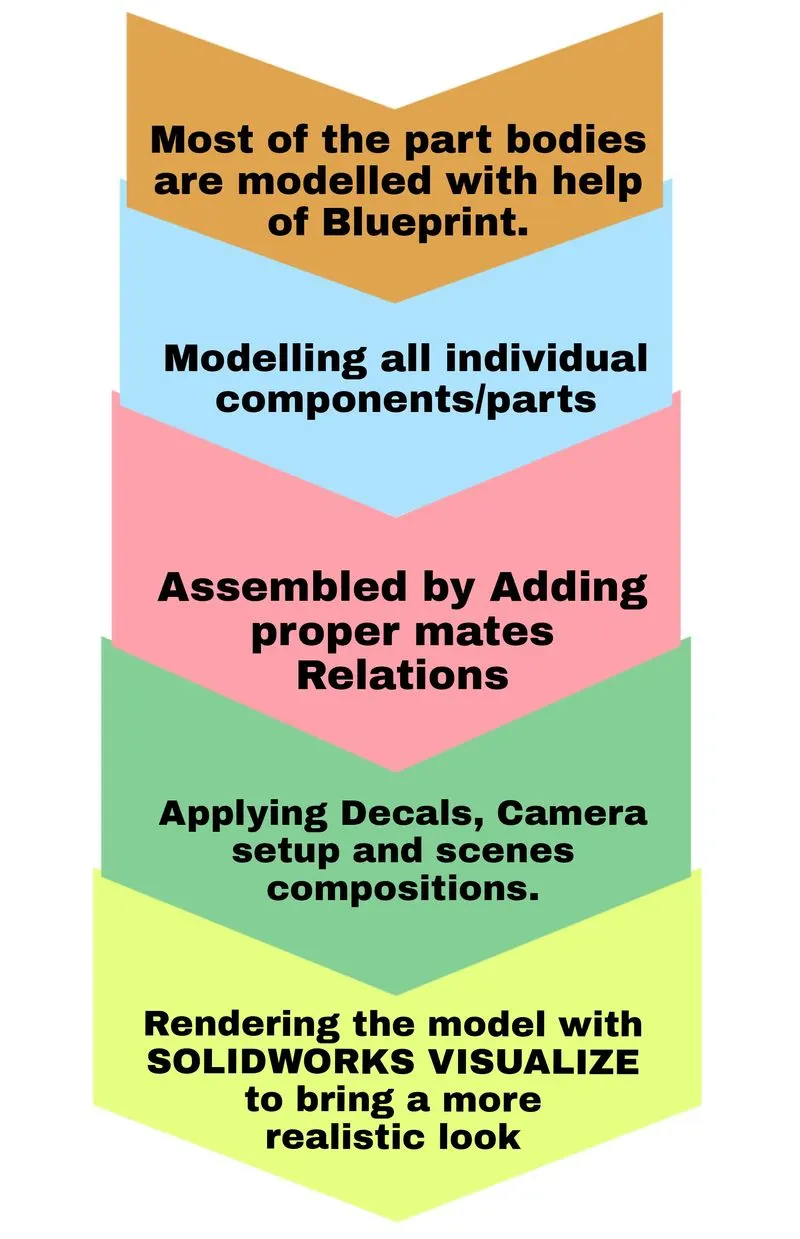
• Most of the part bodies are modelled with help of Blueprint.
• In this report we had discussed about the modelling, assembling and rendering of SUNSEEKER PREDATOR YACHT and included with tools which are used to model the YACHT as well as the quick explanation of each parts.
Design Methodology:
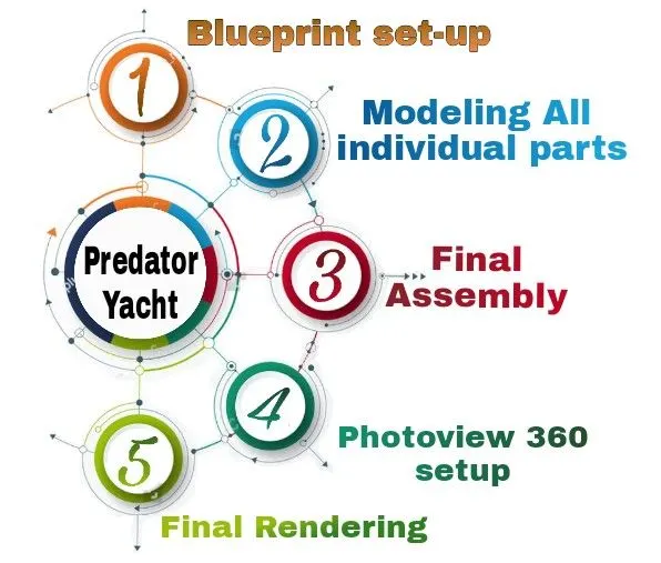
The method used here is bottom up approach which defines that the components are created and assembled with proper mates. For design of yacht we use blueprint setup of the yacht. procedure as follows,
1) Blueprint set-up
2) Modeling All individual parts.
• Hull
• Superstructure
• Radar
• Radar mast
• Garage door
• Propeller
• Front, Middle, and Rear seat
3) Final assembly model of the Predator Yacht
4) Photoview 360
Applying Decals, Camera setup and scenes compositions.
5) Final Rendering using Solidworks Visualize.
Flowchart:
DESIGN APPROACH:
DESIGN INTENT:
In this project, we will be able to sketch and build an entire American Predator Yacht using SOLIDWORKS to understand the 3D- Modelling methodology of Surface Modelling,
and learn, curve generation, surface creation from curves and sketches, different types of surfaces:
• boundary surfaces
• lofted surfaces
• filled surfaces
• ruled surfaces
• reference planes
• surface trims
• surface knit
• move/copy surfaces
• mirror surfaces etc.
DESCRIPTION:
Parts of an American Predator Yacht:
• Propeller.
• Radar.
• Hull.
• Garage Door.
• Front Seat.
• Middle Seat.
• Rear Seat.
• Superstructure.
• Radarmast.
COMMANDS USED:
SKETCHING:
• Sketch
• Line
• Rectangle
• Circle
• Arc
• Spline
• Fillet
• Mirror
• Dynamic Mirror
• Sketch Picture
• Smart Dimension
• Offset Entities
• Convert Entities
• Intersection Curve
• Trim Entities
• Extend
• Linear Sketch Pattern
• Circular Sketch Pattern
FEATURES:
• Extruded Boss: Extruded a sketch or selected sketch contours in one or two directions to create a solid feature.
• Revolved Boss: Revolves a sketch or selected sketch contours around an axis to create a solid feature.
• Swept Boss: Sweep a closed profile along an open or closed path to create a solid feature.
• Lofted Boss: Adds material between two or more profiles to create a solid feature.
• Extruded Cut: Cuts a solid model by extruding a sketched profile in one or two directions.
• Revolved Cut: Cut a solid model by revolving a sketched profile around an axis.
• Swept Cut: Cuts a solid model by sweeping a closed profile along an open or closed path.
• Fillet: Creates a rounded internal or external face along one or more edges in solid or surface feature.
• Chamfer: The chamfer tool creates a beveled feature on selected edges, faces, or a vertex.
• Shell: Removes material from a solid body to create a thin walled feature.
• Reference Geometry: It defines the shape or form of a surface or a solid.It includes items such as planes, axes, coordinate systems, and points. You can use reference geomentry in the creation of several kinds of features.
• Curves: You can create several types of 3D curves.
• Dome: Select one or more planar or non-planar faces you can apply domes to faces whose centroid lies outside the face this allows you to apply domes to irregularly shaped countours.
• Combine: It can manually combine the solid bodies.
• Split: It is able to split faces on multiple bodies.
• Pattern: Pattern repeats the selected features in an array based on a seed feature. You can create a linear pattern, a circular pattern, a curve driven pattern, a fill pattern, or use sketch points or table coordinates to create the pattern.
• Mirror: Mirror copies the selected features or all features, mirroring them about the selected plane or face.
SURFACING TOOLS:
• Extruded Surface: Creates an Extruded surface.
• Swept Surface: Creates a surface feature by sweeping an open or closed profile along an open or closed path.
• Lofted Surface: Creates a lofted surface between two or more profiles.
• Filled Surface: Constructs a surface path within a boundary defined by existing model edges, sketches or curves.
• Offset Surface: Creates offset surfaces using one or more contigous faces.
• Ruled Surface: Insert ruled surfaces from edges.
• Delete Face: Deletes faces from solid bodies to create surface or delete faces from a surface bodies.
• Extend Surface: Extends the edge, multiple edges or the face on a surface, based on end conditions and extensions type.
• Trim Surface: Trims a surface where one surface intersects with anouther surface, a plane or a sketch.
• Knit Surface: Combines two or more adjacent, non-intersecting surfaces together.
PARTS MODELLED:
1) BLUEPRINT SETUP:
A blueprint is a reproduction of a technical drawing or engineering drawing using a contact printing process on light-sensitive sheets. A blueprint is a guide to creating a design or pattern that can be followed. They were easy and fast to read.
For Solid modelling and Surface modelling of Yacht, in this project I have taken some reference of blueprints. The setup of blueprint is shown as below. The main thing to consider while modelling is that it is used as a reference only, accuracy of sketching might slightly differ from the blueprint.
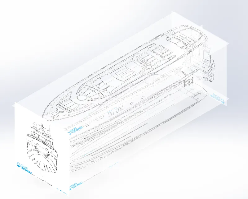
The above shown Blueprint was used to model the Yacht in a fully defined constraints. For setting up the Blueprint the Sketch pictures options were used and placed the different blueprints at the required planes.
2) HULL:
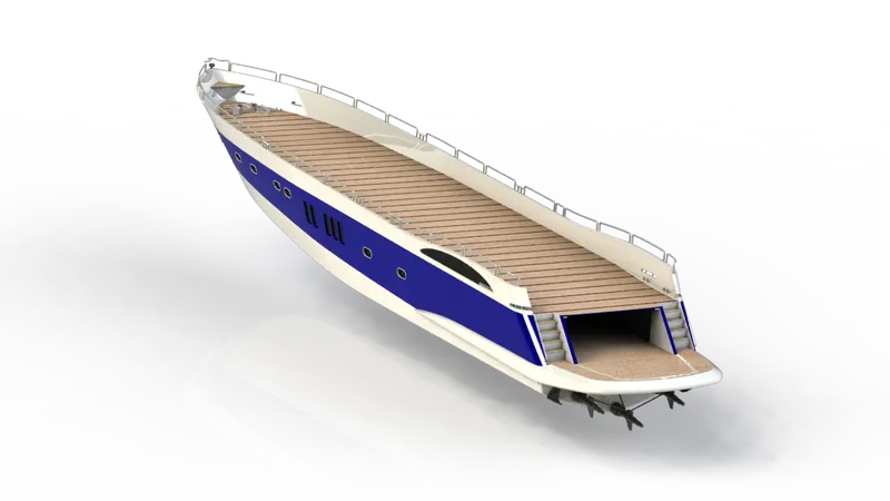
Hull is the base of the yacht and it is a symmetric model. Therefore it is enough to model one half and the other half could be mirrored.
First, the hull is developed in surface modelling, then after completing the model by surface it is converted to solid and proceeded with solid modelling. This is because hull consists of surface with complex curvature, therefore it is wise to model with surface then convert it as solid.
The Design of Hull involves preparation of outer shell surface and the deck surface. The outer shell is drafted with the required curves initially and are extruded and lofted, to obtain the required surface the cures are drawn on different planes and they are projected so that the required curvature is obtained in between the planes
Features used :
• Sketch
• Project Curve
• Surface Loft
• Surface Trim
• Surface Extrude
• Surface Knit
• Surface Fill
• Shell
• Cut Extrude
• Fillet
• Chamfer
• Sweep
• Boss Extrude
• Revolve
• Dome
• Helix/Spiral
• Linear Pattern
• Add/Delete Face
• Thin Extrude
• Thin cut Extrude
• Split Line
• Offset Surface
• Mirror
3) RADAR:
A Radar marine device acts as a major navigation aid for boaters.
It is a very important device in any yacht/ship.
It helps in detecting boats, birds, landmasses, and weather systems - even if the visibility is less than usual. Radar is a vital navigation component for safety at sea and near the shore
Features used:
• Boss Extrude
• Cut Extrude
• Sketch Pattern
• Split Line
• Mirror
• Fillet
4) RADAR MAST:
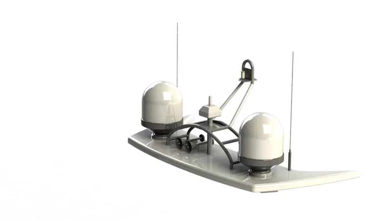
Radar is mated with a part called radarmast and placed on the topmost part of the yacht. it is a symmetric model so the other half is mirrored
The Radar mast supports the radar, antennas, satellite domes and lights. It was designed after importing the top surface of the Superstructure as interface surface.
Features used :
• Boss Extrude
• Revolve
• Fillet
• Boss Sweep
• Mirror
• Project Curve
• Chamfer
• Mirror
5) Front Seat:
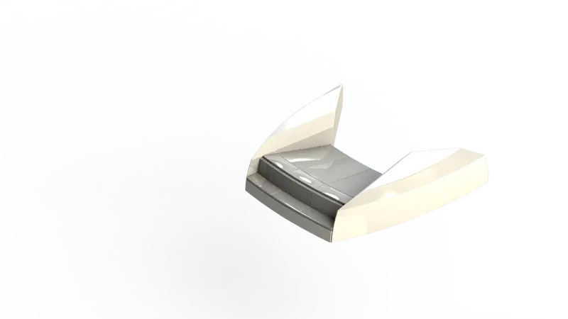
Front seat was placed in front of the Superstructure on the hull. It was designed after importing the deck surface of the Hull as interface surface.
The front seat in our model was placed before the superstructure and also it has sun pads to rest on it. Sun pads are a great way to reclaim lost space on our boat.
Features used :
• Surface Sweep
• Surface Extrude
• Surface Fill
• Surface Trim
• Surface Loft
• Surface Knit
• Revolve
• Cut Extrude
• Cut Thin Extrude
• Chamfer
• Fillet
• Mirror
• Dome
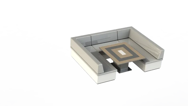
6) MIDDLE SEAT:
The middle seat in our model was placed just behind the back door of superstructure in the middle of the yacht on shaded area. It is modelled based on the surface deck imported from hull.
Unlike other seats it modelled completely in solid modeling.
It is provided with a luxury table to dine out. It can also be used to have casual meetings with co-passengers.
Features used:
• Boss Extrude
• Mirror
• Cut Extrude
• Chamfer
• Fillet
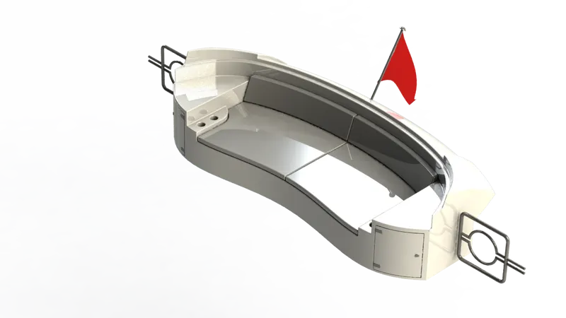
7) REAR SEAT:
Rear seat was placed over the garage behind the Superstructure. It was designed after importing the deck surface of the Hull as interface surface. The rear seat consist of locker racks and steel doors for our stairs. The flag was also placed behind the rear seat since it’s the end part of our yacht. To have a nice view from the yacht while having a drink the rear seat was also provided with a slots to rest the glass or mug.
Features used :
• Surface Sweep
• Surface Offset
• Surface Trim
• Ruled Surface
• Surface Knit
• Surface Extend
• Surface Extrude
• Surface Loft
• Boss Extrude
• Cut extrude
• Chamfer
• Boss Sweep
• Mirror
• Revolve
• Fillet.
8) Garage Door:
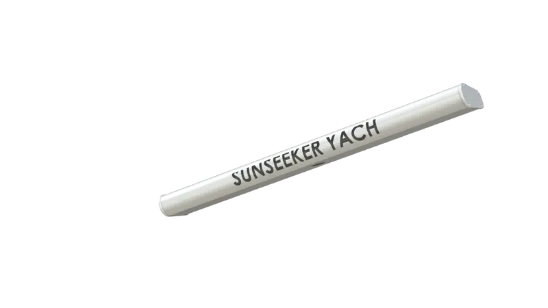
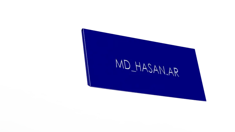
This part is modelled in a solid model which is the part that is extracted from the hull structure rear part using split entities option and is been saved using different file name. It is a symmetric model, therefore the other half is mirrored. The name is engraved using text and cut extrude (offset from surface) commands. it is edited to fit in the hull a cover or door to the garage space created for storing or equipments or vehicles.
Features used:
• Cut Extrude
• Shell
• Mirror
• Fillet.
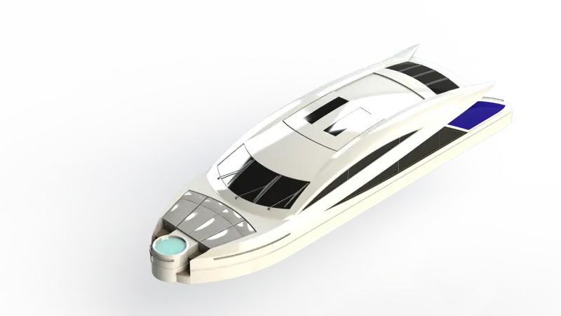
9) Superstructure:
The most complicated part of the whole yacht design is its superstructure which is placed on the top of the hull. It is also a symmetric model therefore it is enough to model one half so that the other half could be mirrored.
This super structure also designed with the help of the imported blue print top, front and side views. It is modelled in a way same as hull, the model is started in surface modelling with a deck surface imported from hull as reference. The desired surfaces are modeled and the surface model is converted into solid and proceeded with solid modelling.
Features used:
• Surface Sweep
• Surface Knit
• Project Curve
• Surface loft
• Surface Fill
• Surface Extrude
• Surface Trim
• Ruled Surface
• Surface Extend
• Fillet
• Cut-Extrude
• Face Delete
• Boss Extrude
• Surface Offset
• Thickness
• Dome
• Boss Sweep
• Extrude Thin
• Split Line
• Mirror
• Chamfer
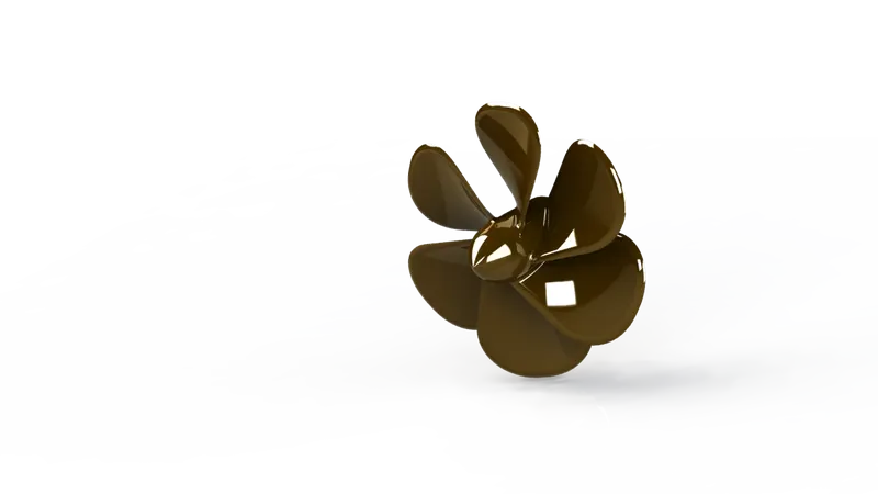
10) Propeller:
Propeller looks like a fan, it is placed such that it is submerged inside water. Propeller is the main component for the navigation of yacht/ship, it receives power from the engine, it helps the yacht/ship move forward or backward by pushing the water in opposite direction, for instance if the ship is moving forward the propeller pushes the water backward and vice versa
Its rotary motion through the air creates a difference in pressure between the front and back surfaces of its blades. It provides thrust so that the yacht moves easily.
Features used:
• Sketch
• Revolve
• Loft
• Cut Extrude
• Circular Pattern
• Fillet
ASSEMBLY OF YACHT:
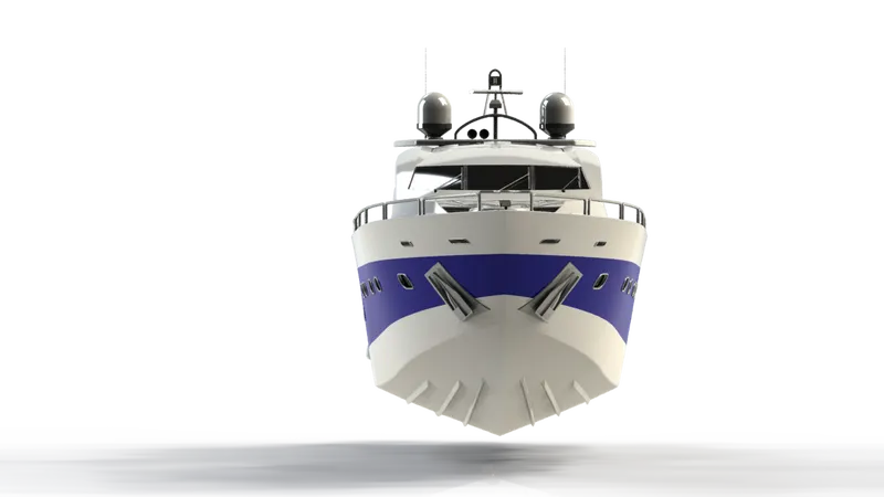
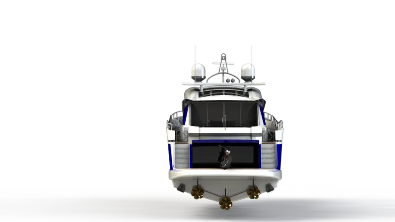
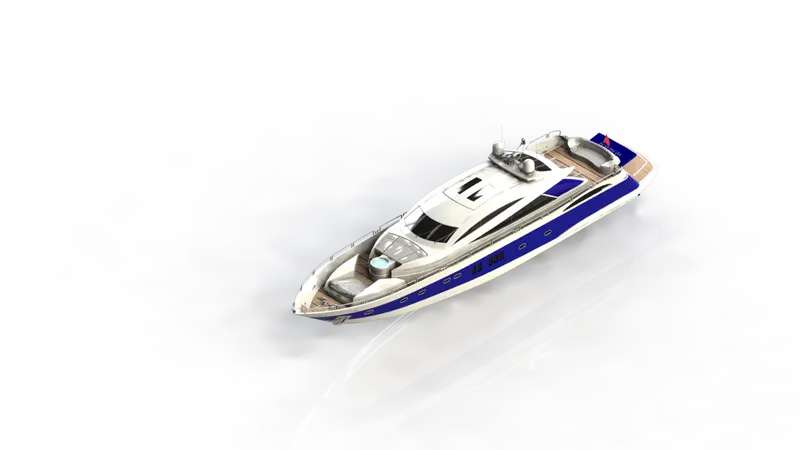
After modelling the individual parts Import all the parts manually in an order by using Insert Components option.
Then fix the Hull part by applying the coincident mate to the Top, Right and Front planes of the Assembly and Hull respectively mated with required constrains. The commonly used constrains are coincident, offset, concentricity etc.
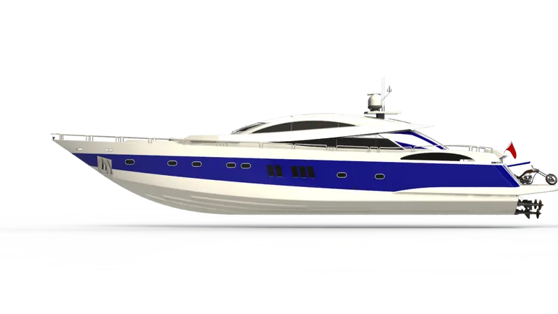
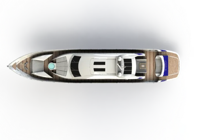
First, the hull is imported in SolidWorks assembly work area and is fixed. Since parts like superstructure, front seat, middle seat, radarmast are modelled based on the deck surface of previous parts there is no need to position the above mentioned parts it will position itself in the assembly environment when we import the parts and they are fixed automatically.
RENDERING:
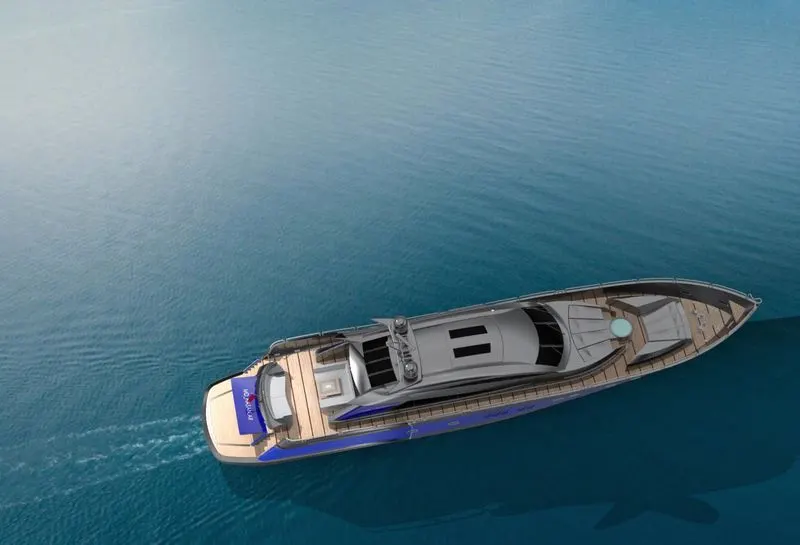
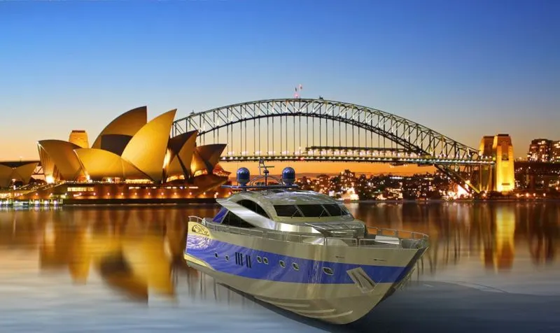
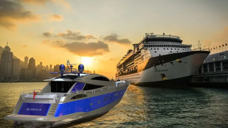
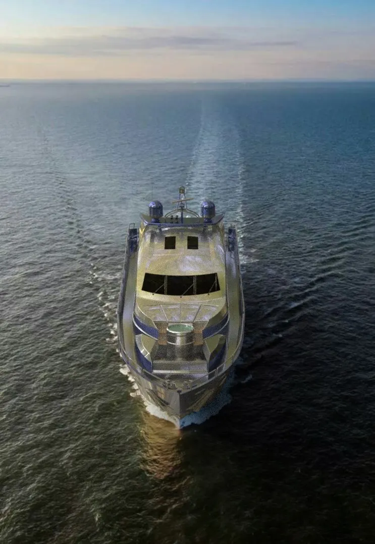
Rendering of the Solidworks model is done using PhotoView 360 and Solidworks Visualize.
• PhotoView 360 is a SolidWorks add-in that produces photo-realistic renderings of SolidWorks models. The rendered image incorporates the appearances, lighting, scene, and decals included with the model.
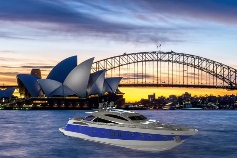
• SOLIDWORKS Visualize: In this we need to import required solidworks part/assembly components and by Backplate we get the rendered output. the product to be seen under environmental conditions with different views. It gives a realistic view of the model relative to the environment
CONCLUSION:
In this project, I understand the importance of the Blueprints and proper
arrangement of feature tree it made whole modelling easy and confusion free.
Moreover, This project helps me to enhance my designing skills and I learned Solidworks software as a design tool in an industrial manner. And it help me to become industry ready for the role of Mechanical Design Engineer.
Thus, the overall DESIGN OF AN AMERICAN PREDATOR YACHT project was successfully modelled, Assembled and Rendered