Week 9 - Challenge 1 - Base Bracket Design
<!--StartFragment-->
BASE BRACKET DESIGN
Aim:
To Create the Base Bracket Plastic component class-B and class-c surface by given Class-A surface. Also make tooling axis and draft analysis to check the manufacturing feasibility.
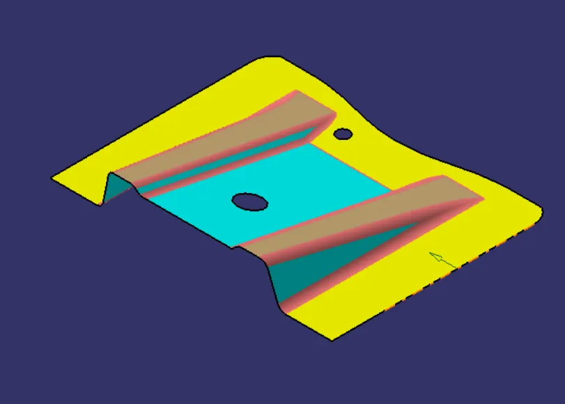
Class A Surface:
Class A surface means visible surface. it will give styler.
In Class A surface we must Check the connectivity of the Surface. Ensure that there is no gap between the component, using join command. And also we can visually check it or by clicking boundary command.
Creation of Tooling Axis:
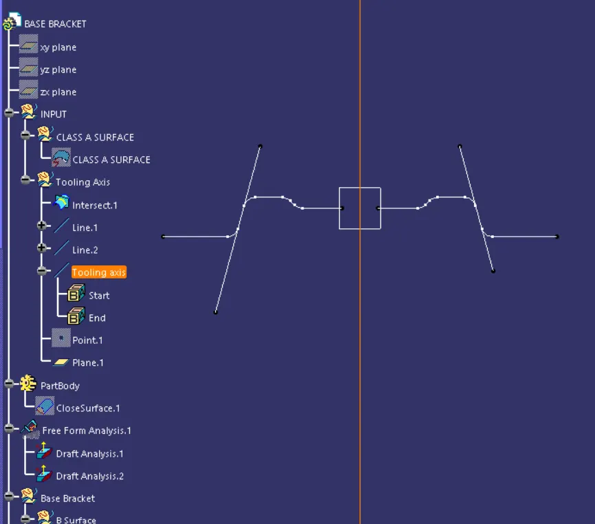
Study the class A surface to find the "Tooling Axis" of the component. The tooling axis is nothing but the axis of cavity opens.
Visually check all three axis to find the best possible tooling axis.
From given Class-A surface Z-axis is the best suitable tooling axis.
Intersection line created against z axis and Class-A Surface.
Creating the Bisecting line by extending slope lines on either sides. Thus the tooling axis created.
Creation of Draft Analysis:
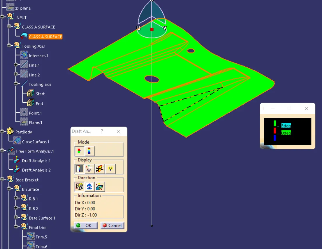
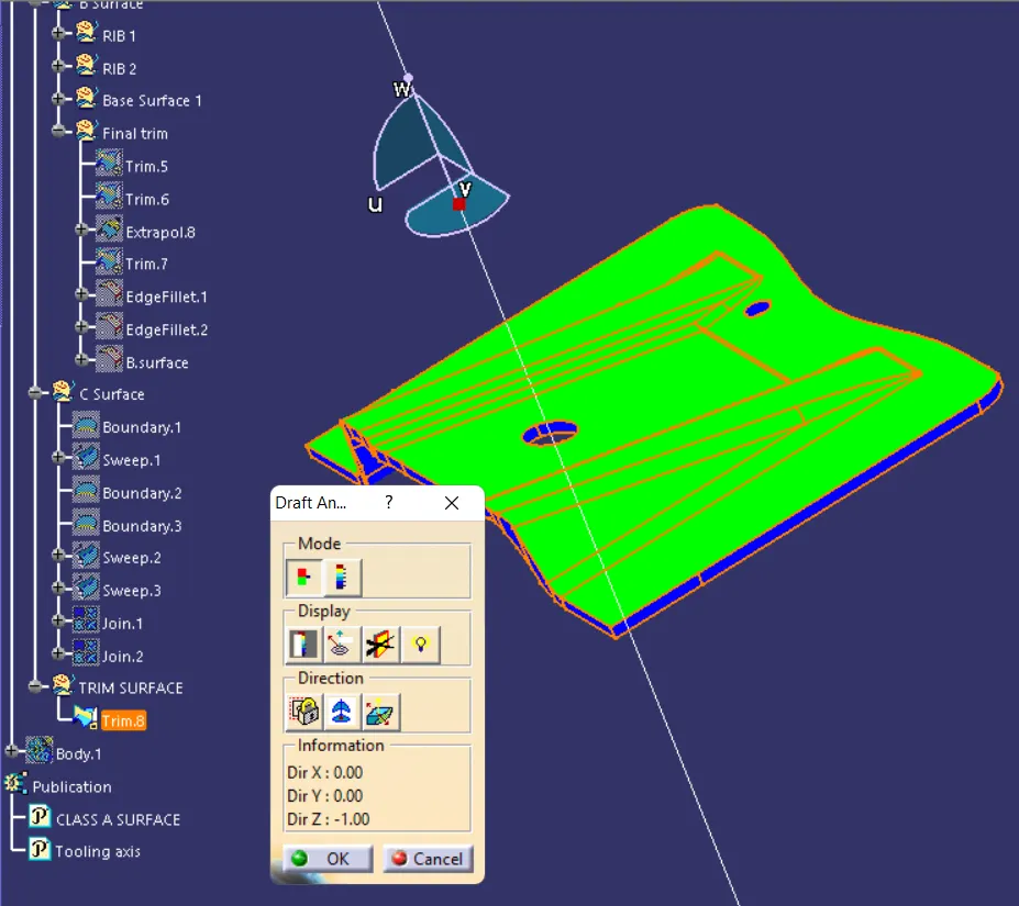
Insert >>Analysis >> Feature Draft Analysis
Above command is used to perform draft analysis.
Select the compass and set it on the tooling axis in upward direction.
By clicking on the surface, The color scale on the bottom visualizes, whether the draft angle meets the requirements or not (3 deg) by indicating the colors Green, Blue and Red.
In plastic design, the draft angle that is considered in the OEMs is 3 degree. If the part attains 3deg then the whole part turned into green color. If blue was visible that meant that the analysis was inversely done so just by flipping the direction.
Creation of Class B:
Now for Class B creation, we have extracted surface from Class A and untrimmed them to obtain the original parent surface.
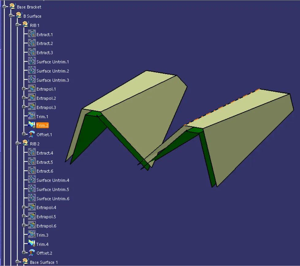
These surfaces is a copy of the class A surface. It offset at a distance equal to the thickness of the part.
After offsetting, all the surfaces are trimmed into the required shape.
Required fillets are given to the surfaces with a value of radius+thickness of the part i.e. (3 + 2.5 = 5). 5mm was given.
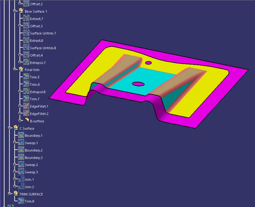
The final surface created is shown below and is surface B
Creation of Class C Surface:
It is the combination of Class A, Class B and Class C surfaces. To create a class C surface, I used the sweep command by considering the outer boundary of the class A surface.
Now select the outer boundary and tooling axis, give 3 deg in the angle
In the same manner, the two holes on the sheet were also swept by creating the boundaries and later sweeping them both simultaneously
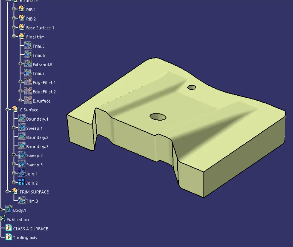
The required 3 surfaces were joined together taking holes into consideration too. All the three surfaces were lastly trimmed to get the final part which is shown below
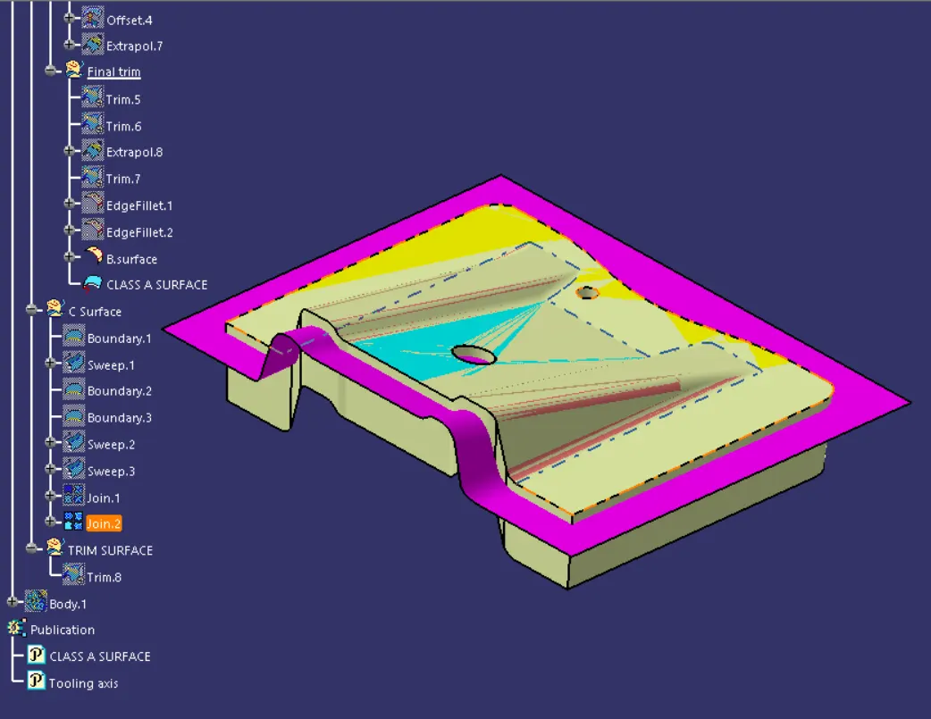
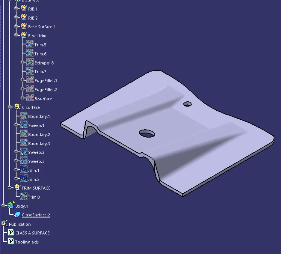
To make sure that there is no open boundry between class A, B and class C surfaces to make the hollow part into solid body by going the part body option and then selecting close body surface.
Conclusion :
Thus we created base bracket Class B & C from given Class A. Then tooling axis were created and draft analysis done for given Class A. Also another draft analysis done for final output and found ok with 3 deg draft.
<!--[endif]-->
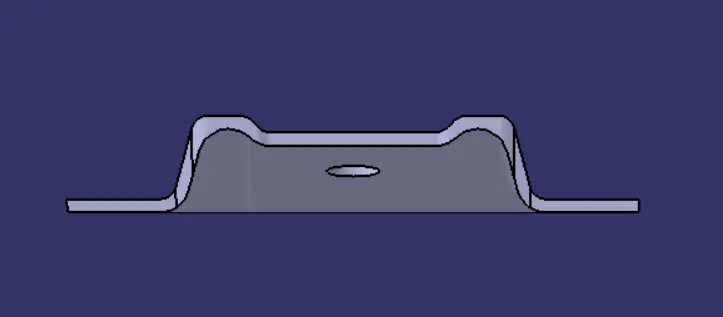 Front view
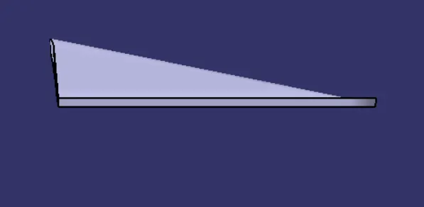 Side view
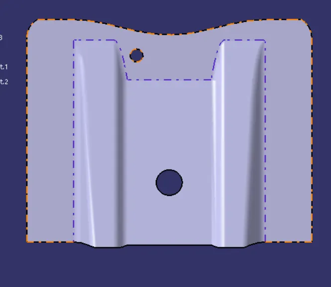 Top view
<!--/data/user/0/com.samsung.android.app.notes/files/clipdata/clipdata_230914_214857_620.sdoc--><!--EndFragment-->