DESIGN OF AN AMERICAN CHOPPER BIKE AND REALISTIC RENDERING
DESIGN OF AN AMERICAN CHOPPER BIKE :
Aim:
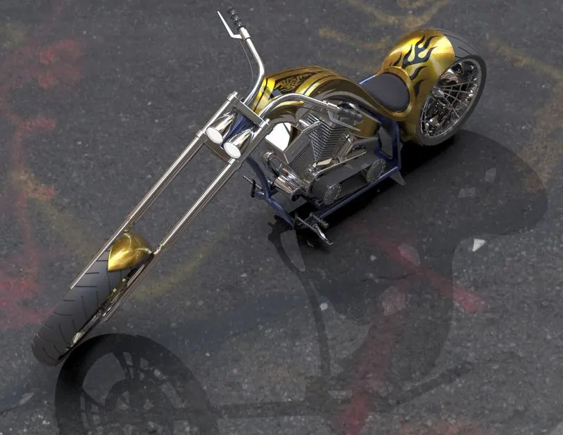
To sketch and modelling a different parts of an American Chopper Bike, Assemble them together, apply decals and rendering the model by photoview 360 in SOLIDWORKS and Photo-realistic rendering using Solidworks Visualize
OBJECTIVE:
The main objective of this project is To learn and apply all solid and surface modeling techniques and mastering some very important features/tools and To get a good understanding in the basics of SolidWorks part modeling, assembly and Photorealistic rendering
To get a practical Rendering knowledge in photoview 360 and SOLIDWORKS VISUALIZE to set the Appearances, decals, scenes, cameras, lights. And to Render the model with appropiate quality and enviornment To bring a more realistic look
Also, to understand the mechanical design process by applying the theory of CAD and basic engineering principles and practical. Learning SolidWorks is actually an industrial approach, and this Project has enhanced creativity and skills in mechanical design which also make us industry ready for the role of mechanical design engineer and to be able to design an industrial product keeping the design intent.
INTRODUCTION:
In this project, I had detaily explained about how I designed this American Chopper Bike. It is a type of custom motorcycle which employs radically modified steering angles and lengthened forks for a stretched-out appearance.
The design initially started with ideation process followed by part modelling of all individual parts one by one.
After that parts are assembled using proper mates and relations in assembly environment in Solidworks and then rendered using SOLIDWORKS visualize.
DESIGN METHODOLOGY:
While designing anything in the industry it has to be passed from certain steps.
1. It first started with ideation. In ideation, the designer tries to portray the sketch on paper which is already created in his mind by doing some brainstorming. After several trials and errors, one sketch is finalised.
2. Modelling various components/parts
In this part modelling, first the 2D sketch of the part is sketched using the tools in sketch tab and then the 2Dsketch is converted into a 3D part using features in the features tab.
3. Assembly of components/parts
*Once the modelling of all parts is done they are assembled in an assembly environment.
4. Setting up decals and camera, scenes, environment, lights.
5. Final rendering using rendering tools like photo view 360, and SOLIDWORKS visualise.
Flowchart: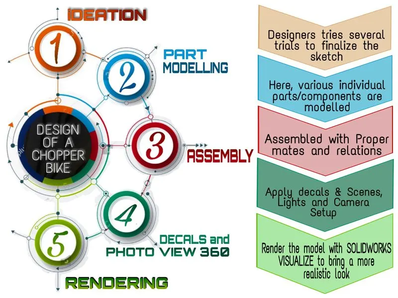
The Above flow chart represents the whole process i have done for designing an American chopper from beginning to end.
DESCRIPTION :
Solid modelling of all the parts of the American Chopper Motorcycle and the sketches used as well as its features is explained in this section briefly.
Tools and Features:
* Boss Extrude: Extrude feature allows to form 3D solid body from surface or plane.
* Extrude Cut: Extrude cut feature used to cut/remove the 3d object in linear path according to sketch.
* Revolve cut: Revolve cut is used to cut or reduce the extrude of cylindrical round surface.
* Fillet: Fillet is a feature used for making round internal or external edges to avoid sharp edges and make it smooth.
* Shell: Shell tool hollows out a part and creates thin-walled features on all sides, leaving the selected faces open.
* Linear Pattern: The linear parent is used to create a different number of instances required to create the pattern linearly.
* Curve Driven Pattern: Curve driven pattern is used to make any pattern which followed by the curve is sketched before.
* Move/copy body: This feature is used to move/copy the 3D body to one place to another place.
* Sweep cut: Sweep cut is same as sweep feature but its directly proportional to sweep which makes a cut along with the sweep path.
* Swept Surface: sweep surface command allows you to sweep a surface along a given curve, to form a complex surface geometry.
* Loft Surface: Surface loft feature is used to generate complex surfaces by specifying cross sections made from sketches.
* Split surface: As the name suggests, split surface feature allows you to split a surface into two separate surfaces
* Knit surface: Surface knit feature is used to merge 2 surfaces into one surface.
* Projection Curve: Projection curve is a 3D curve which is projected on the basis of the two different 2D curves in two different planes.
* Blocks: You can make save, edit and insert blocks from the drawing items and sketch entities that you use often such as standard notes, title blocks, label positions and so on you can attach blocks to geometry or to drawing views
* DECALS: A decal is something called a “transfer”, and it consists of a picture, image, pattern, or design that’s printed on metal body. We have added decals on gas tank, rear fender and oil tank of chopper. It gives nice appearance to the chopper.
Parts of the Chopper Bike:
1. Transmission Belt
The main function of transmission belt is to transmit power.
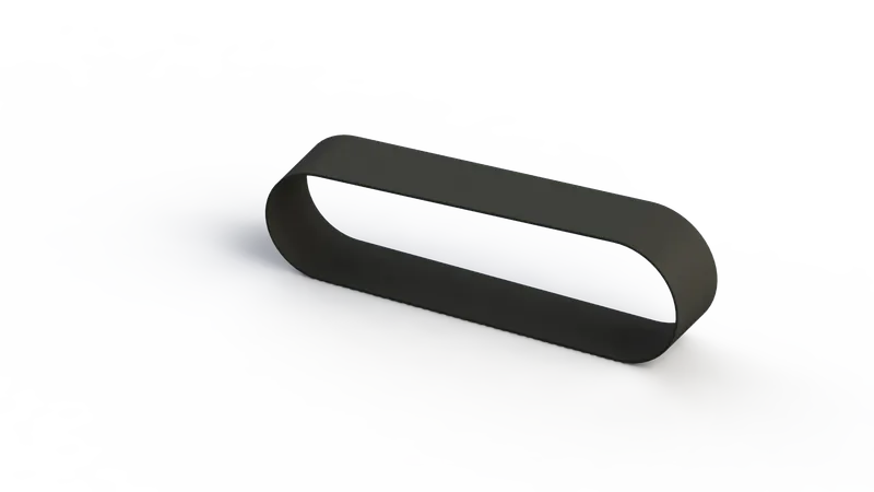
It is a simple model created using very fewer tools like
• Extruded Cut
• Loft
• Dome
• Offset entities
• Extrude boss
• Fillet
• Appearances, etc.
Transmission belt is located at the round surface of the pulleys. To transmit the power with help of pulleys. the appearance given is matte rubber
2. Kickstand
Kickstand allows the bike to stand upright without any external support.
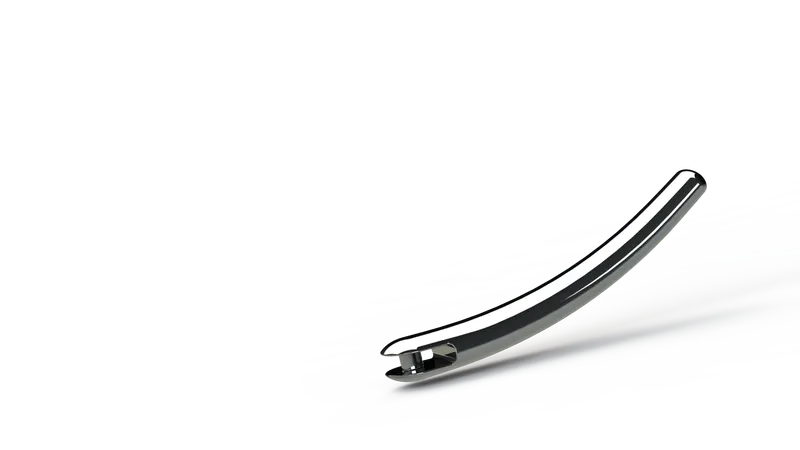
The features used for modeling the kickstand such as
• Loft boss
• Extrude boss
• Extrude cut
• Dome
• Split
• Fillets
• appearance, etc.
Kickstand for this bike is of a very simple kind made by the application of sweep feature and the Dome is applied at the ends of the kickstand.
3. Front Fender
The primary purpose of the fender is to prevent mud, dust and rocks from being thrown towards the rider or bike components.
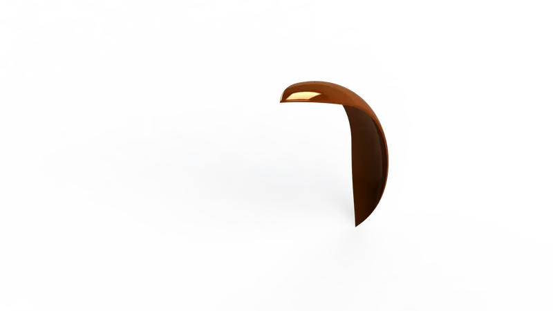
The features used for modeling the front fender are,
• Offset entities
• Trim entities
• Revolve boss
• Dynamic Mirror
• Split
• Appearances, etc.
Here we revolved the sketch using an axis and created half curved solid body. Some sharp edges designed on the both sides of fender by using the split tool the material is removed. The edges of the fender are filleted.
4. Rear Fender
The rear fender is thicker but shorter compared to the front fender. It doesn't have a pointed end like the front fender, rather rounded end as in the Idea of sketch.
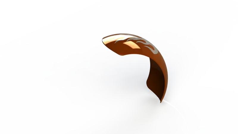
The features used for modeling
• 2D Sketch
• Surface Trim
• Extruded Cut
• Fillet
• Shell
• Offset Entities
• Revolve boss
• Appearances, etc.
Same procedure is used to make rear fender as it was used in front fender. Only the difference between the two are sizes as according to the size of the tire. Revolve and split tools are the most used tools here.
5. Oil Tank
It simply holds the oil. The oil tank is placed above the engine block which is also made hollow inside by shell feature.
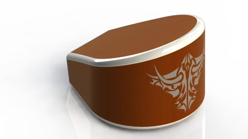
Features used to create the Oil tank:
• 2D sketch
• Surface Extrude
• Fillet
• Surface Trim
• Surface Knit
• Shell
• Boss Extrude
• Combine
• Appearance, etc
Fillet is applied on the outer edges to make it round. The appearance given to the oil tank is sienna colour and the edges filleted are given white paint.
6. Chain
Chain is used to transmit power from the engine to rear wheel through sprockets.
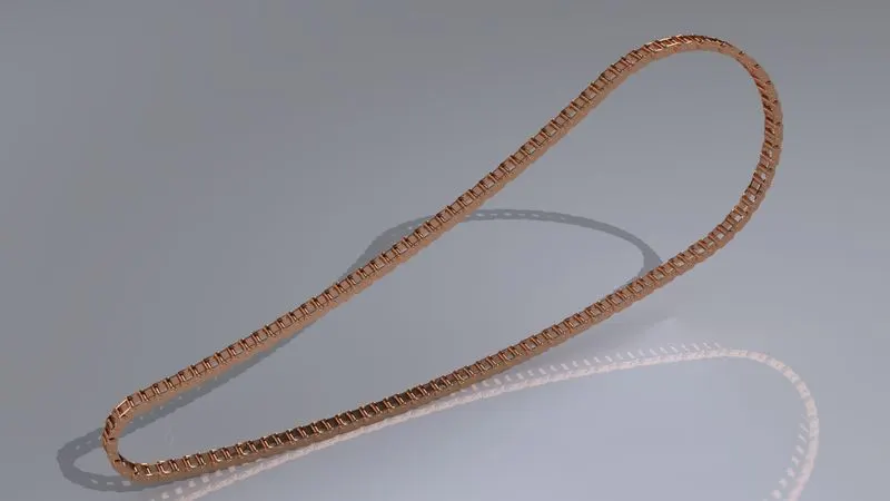
Some of The features used for modeling the chain are,
• 2D sketch
• Mirror
• Curve Drive Pattern
• Trim entities
• Fillet
• Blocks
• Extrude boss
• Linear Patterns
• Appearances, etc.
It is the most complex part of the whole design project. It consists of 390 bodies including separate bodies for all the inner plates, outer plates, and the pins.
It is essential to keep all the elements of this chain as a separate body (BLOCKS) because it has to rotate along the curve and around the sprocket which is not possible if it is merged to make a single body
7. Pedal
A pedal is a strong rigid body it is used to rest the foot while riding bike and used to operate brakes or switch gears in the vehicle. 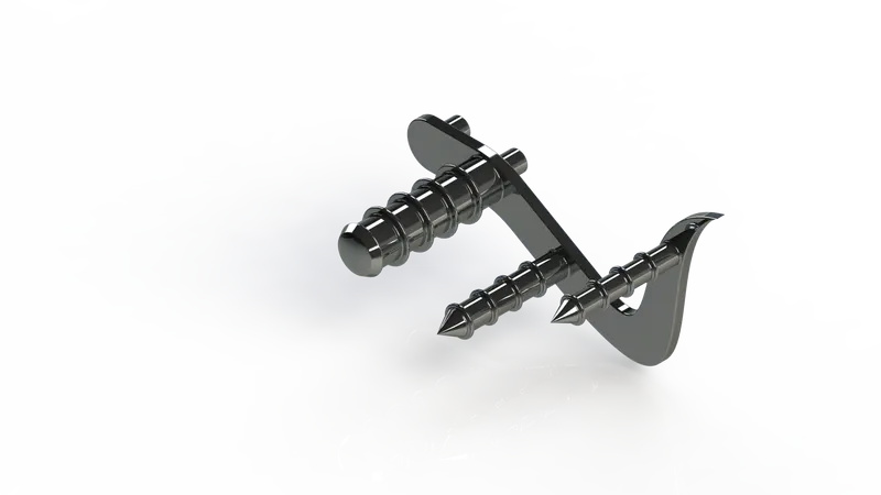
There are two pedals, left and right. Among them, only the right pedal was sketched and designed in the part design environment and the left was made using the in-context features of the assembly environment.
Features commonly used to create the Pedal:
• Extrude
• Revolve
• Dome
• Linear pattern
• Fillet
• Chamfer
• Appearance, etc.
8. Front Wheel
Front wheel helps to turn the vehicle while moving.
It is thinner and having larger diameter than the rear wheel to manage impact better than the rear.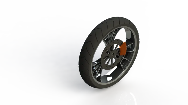
Front wheel is designed to be a multi-body part consisting of the rotor, sprocket, rim, tire, and the calliper all are made to be single bodies. the spider webbed spokes were created by using splines and offsetting them. Mostly used features,
• Extruded Cut
• Revolve boss
• Trim entities
• Boss Extrude
• Sketch Fillet
• Chamfer
• Linear Pattern
• Mirror
• Circular Pattern
• Appearance, etc.
9. Rear wheel
The rear wheel is the powered wheel in bikes. It propels the bike. 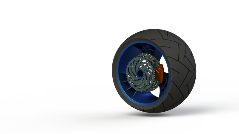
Just like the front wheel, it is also designed to be a multi-body part.
The steps were followed same like front wheel and appearance given is also same only the component added here sprocket to link the chain.
The features used for modeling the rear wheel are,
• Extrude boss
• Planes
• Revolve boss
• Revolve Cut
• Fillet
• Chamfer
• Linear Pattern
• Mirror
• Circular Pattern, etc.
10. Front Fork
The front fork connects wheel and axle to the vehicle chassis. It is the most unique part of this American Chopper bike. It is typically made with triple clamps.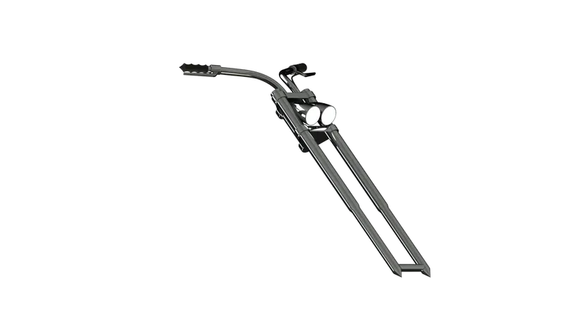
First the half portion of the front fork has been created and the whole body is mirrored about the plane. Projected curves were used to model the handles and the cables.
Some of the Features used to create the Front fork:
• Extrude boss
• Revolve boss
• Sweep boss
• Shell
• Split
• Combine
• Move/copy body
• Linear Pattern
• Projected Curve, etc.
11. Chassis
The chassis is the frame that bears most of the load on the bike. And the modelling of chassis starts with using chopper image for reference. 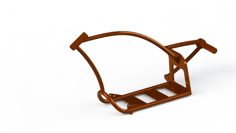
The lower tube is mirrored with respect to the mid-plane. The rear plate supports the rear arm which holds the hub from only one direction so it is designed to be stiff enough. the features used such as,
• Extrude boss
• Combine
• Revolve Cut
• Mirror
• Sweep boss
• Split
• Dome
• Fillet
• Chamfer
• Projected curve
• Offset entities
• Convert entities, etc.
12. Engine
The main part of the bike is engine. It provides necessary power to drive the bike. A picture is taken for the reference for modelling.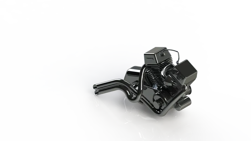
The engine used in this bike is a V engine with two exhaust pipes. It incorporates the cooling fins, spark plug representation, intake and exhaust manifolds, crank shaft, motor and transmission unit
the features used to create:
• Extrude Cut
• Offset entities
• Revolve boss
• Chamfer
• Projected Curve
• Linear Pattern
• Circular Pattern
• Composite curves
• Sweep boss, etc.
13. Gas Tank
Gas tank form an important point of contact between bike and rider. It is hollowed out by shell to make a tank for the fuel inside. 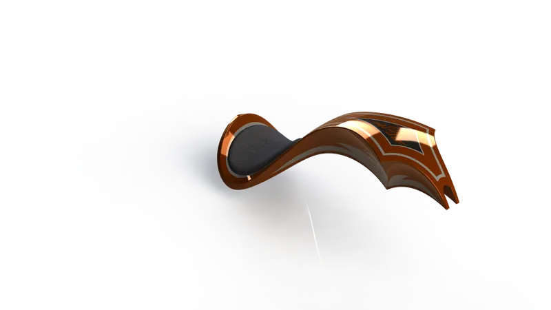
The seat was modelled on the top of the gas tank. The half part of the gas tank first created and then it is then mirrored about the plane. The two separated parts were made single part by using knit feature.
Features used to create the Gas tank:
• Surface Sweep
• Split line
• Surface Loft
• Surface Offset
• Surface Knit
• Fillet
• Projected curve
• Shell
• Mirror
14. Assembly
In order to assemble the parts, all the parts are inserted in assembly file one by one as per the requirement. After that required mates were applied to each and every individual component for proper alignment.
Most widely used mates are:
• Concentric Mate
• Coincident Mate
• Tangent Mate
• Distance Mate
• Angle Mate
• Parallel Mate
• Mirror Part, etc.
which in solidworks comes with an individual category termed as “standard mates”
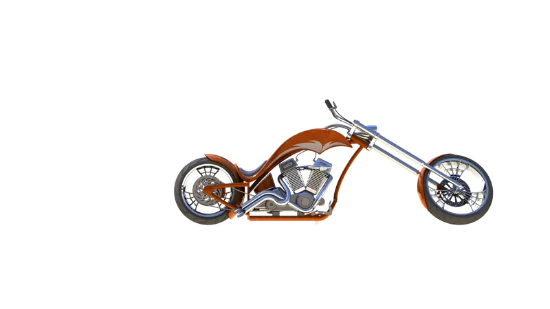
ASSEMBLY CAMERA VIEW
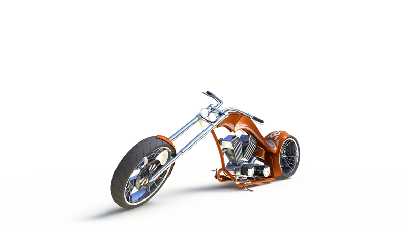
ASSEMBLY FRONT VIEW
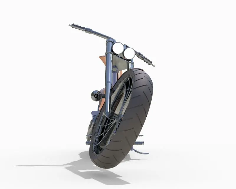
ASSEMBLY RIGHT VIEW
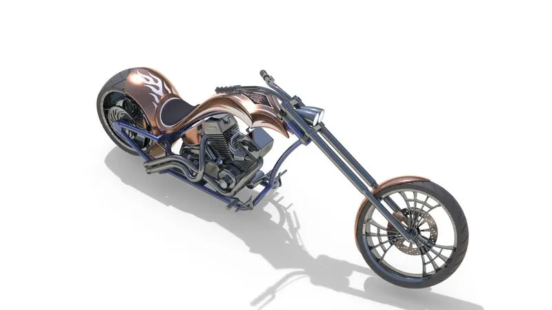
ASSEMBLY ISOMETRIC VIEW
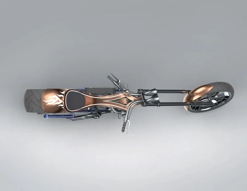
ASSEMBLY TOP VIEW
RENDERING:
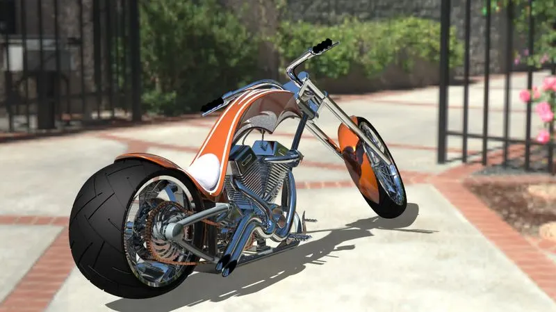
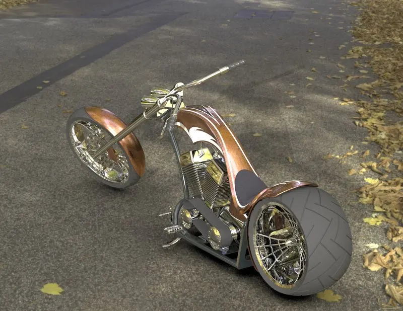
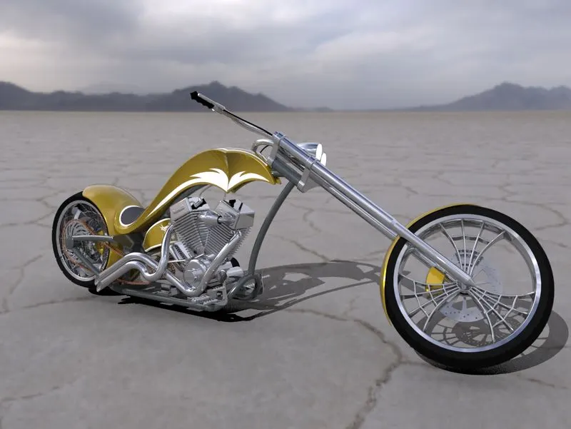
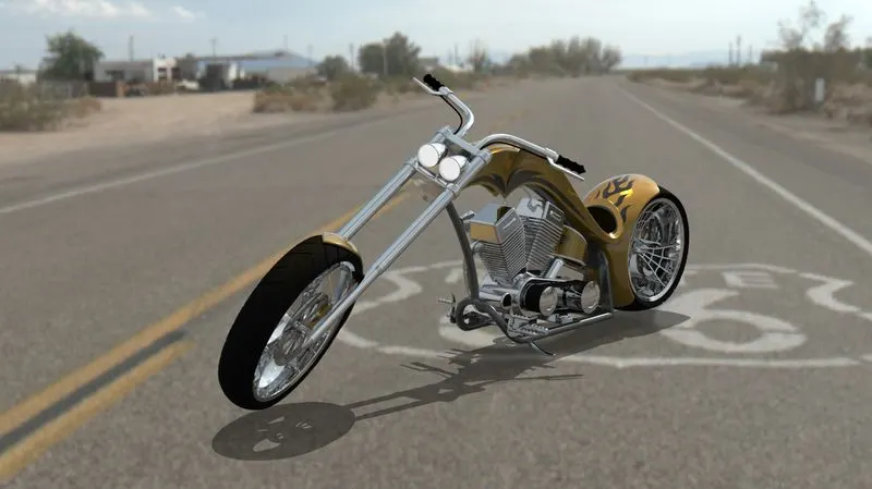
I rendered it in different views. Metallic chrome was applied to various engine components, handle bars, wheels etc. Rubber material was applied to both tyres and belt. Applied few different materials and paints to remaining parts. Then I applied a hdr environment to bring realistic look.
CONCLUSION:
In this project I understand the importance of the Blueprints and proper
arrangement of feature tree it made whole modeling easy and confusion free.
Moreover, This project helps me to enhance my designing skills and I learned Solidworks software as a design tool in an industrial manner. And it help me to become industry ready for the role of Mechanical Design Engineer.
Thus, the overall DESIGN OF AN AMERICAN CHOPPER BIKE project was successfully modelled, Assembled and Rendered.