Week 9 - Challenge 3 - Bumper
AIM
To create the Bumper Plastic component through the given Class-A surface. To begin with, the tooling axis for the given Class-A Surface should be created meeting the requirements of the draft angle and at the end perform the Draft analysis on the model.
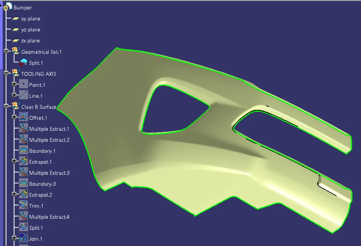
CREATION OF CLASS-A SURFACE
A surface made by the designer which is given as an input to the plastic modeler to work on. It is aesthetic surface
and the outer most surface.
CREATION OF TOOLING AXIS:
Tooling axis is the direction in which a core or cavity of mold opens. This Axis is very important to determine the orientation of the component in mold, core and cavity design.
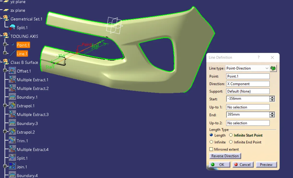
First create a tooling axis with respect to the CLASS A surface by the inertia method by using the steps as follow
• Click “Measure inertia” and select the A-surface then Click “Create geometry” in the Measure Inertia window.
• In the Creation of Geometry window, select Non-associative geometry.
• Click “Center of Gravity”
• The Inertia point is created.
• The component is viewed in all axes namely X,Y and Z.
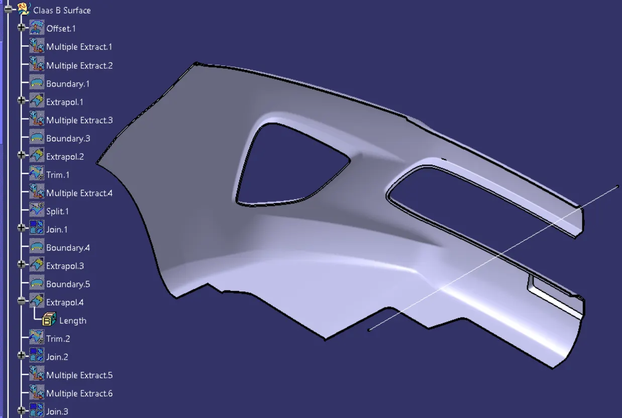
• It is determined that the X-axis will be the direction for the Tooling axis and a line is created Using the CG point and X-direction as direction of the line
Draft Analysis
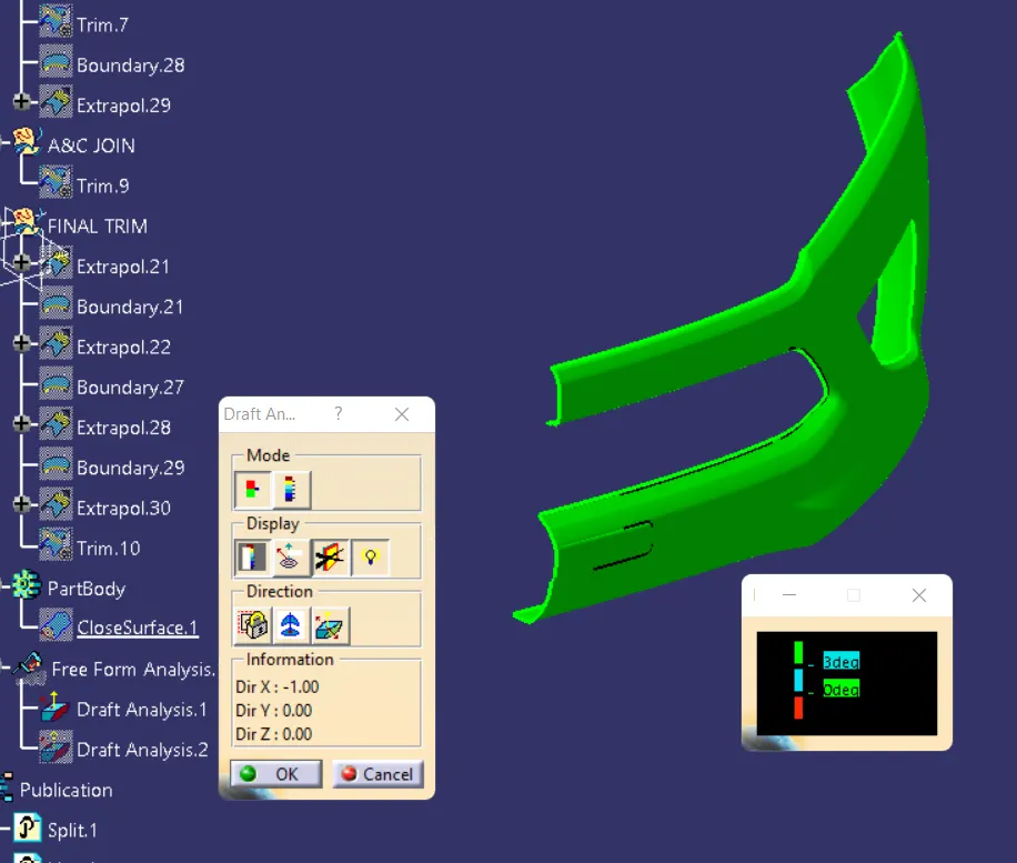
Draft analysis is a most importent thing for a part body design. Its reasult says that the perticular body is manufacturable or not. Even it also analise that how simple or complex will be the manufacturing process. So to do that analysis first we have to create a tooling axis that will be along the movement of mould open and close axis
Now we go to insert< analysis< draft analysis and follow usual procedure to do the analysis.
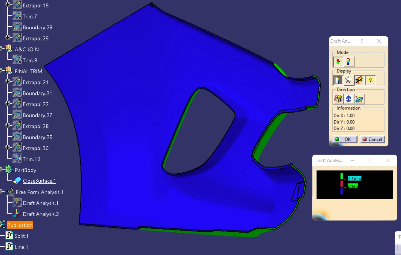
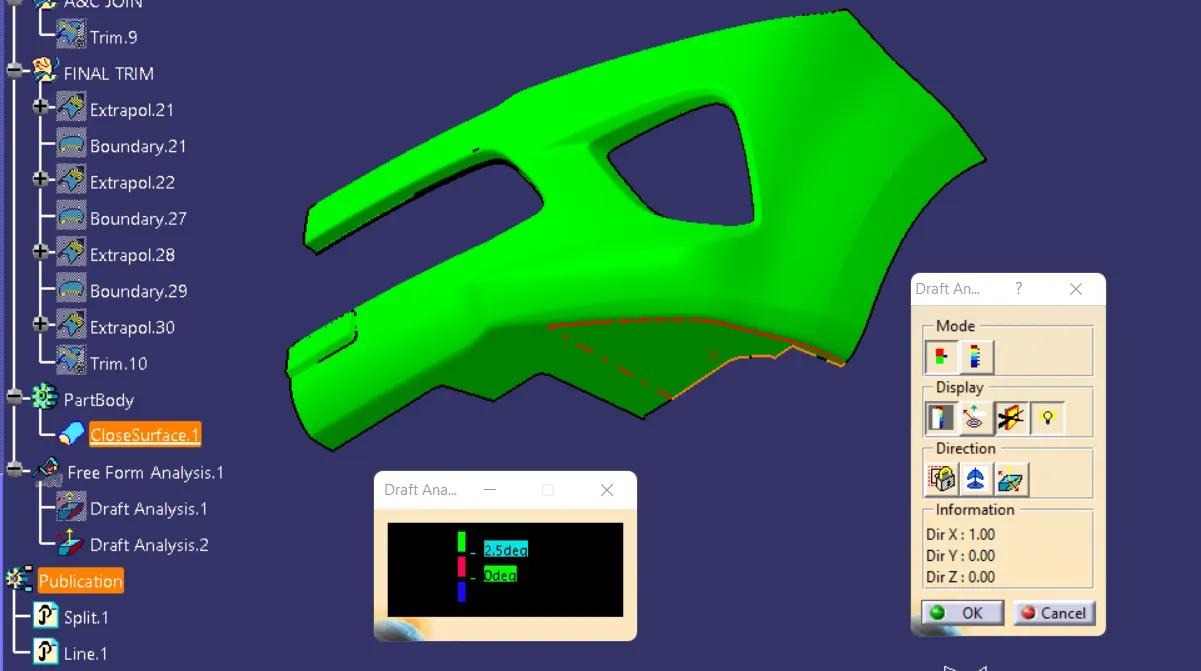
then we need to select the class a surface after that we need to make it into material mode after that we need to place the axis system on the tooling axis then lock the movement of the axis system after that need to click on the class A surface then the surface colour changess as per the criteria as shown in the above figure.
As we intersected to proceed we observed that the side walls are not given any draft. Hence we assume the axis normal to the base surface and parallel to side walls.
CREATION OF CLASS-B SURFACE:
A surface below a certain thickness from the class-A surface is class-B surface. This is the surface that contains engineering aspects of a model.
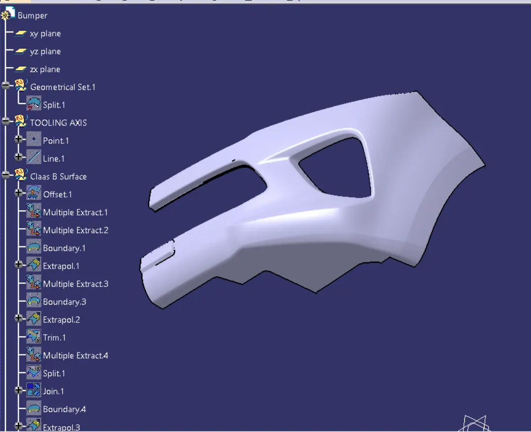
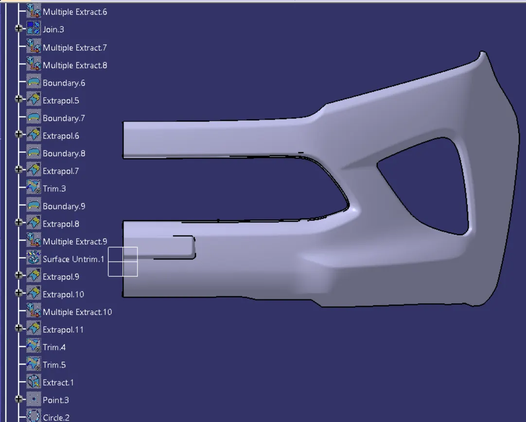
• First create a geometrical set and named it as CLASS B surface and make a offset from the class a surface.
• The Areas where the B-surface has issues are corrected by using extrapolate and boundary function untrim the surfaces and trim it to the required conditions.
• Then give fillets to the sharp edges
• Then using a Multi section, Sweep, Offset and extract. boundry and extrapolate features use trim to make a class c surface.
• B surface created is checked for any gaps or errors by creating a complete boundary
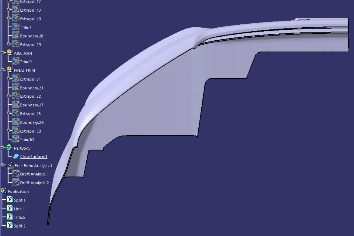
• Finally using a close surface make a part body to create a single surface which will act as the final B-surface.
CREATION OF C-SURFACE :
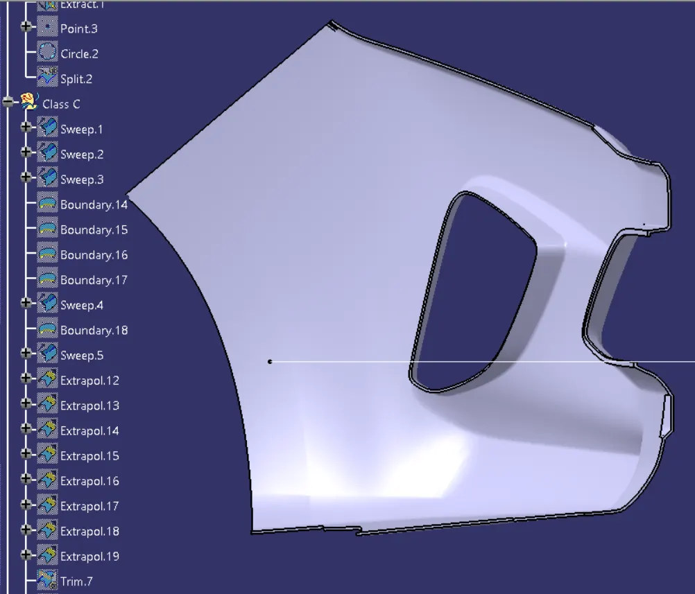
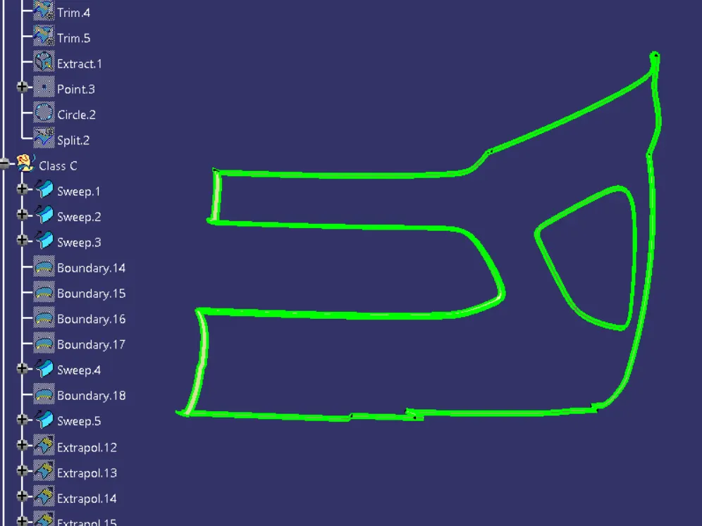
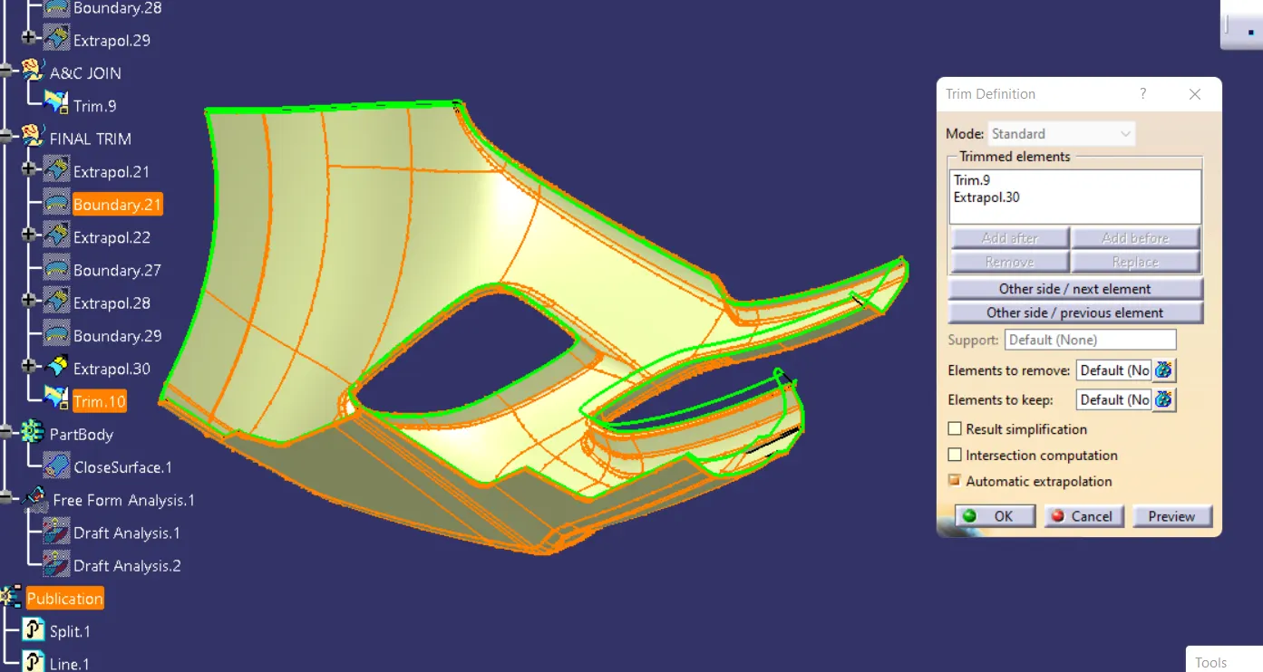
C Surface is nothing but joining part of the both Class A & Class B Surface. So to create the Class C Surface, first create boundaries using 'Boundary' command with using edges of Class A Surface. And then create a surface using 'Sweep' command at a angle of 90 deg. with class A Surface using those boundary. It might create error when try to make sweep with one single boundary of Class A Surface edge, so for that case we have to take several boundaries according to feasibility. And then trim those sweep surfaces with class B surface to make sure there is no excess surface beyond class B surface.
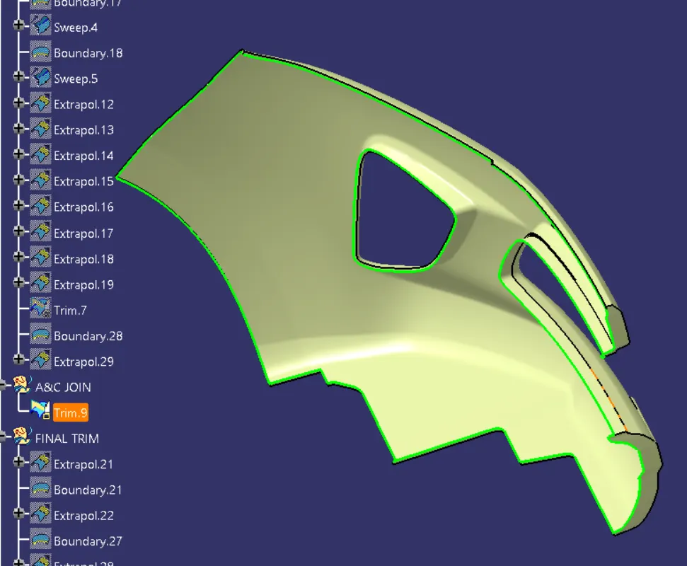
Following is the picture of Class A + Class C surface trimmed together
SOLID BODY CREATION:
After creating all surfaces (A,B,C)are joined together to form a closed body.
To create solid body of that closed surface, make sute there is no open edges. If there is open edges then it would not be possible to create solid body. After make sure, go to part workbench and make the closed surface part a solid body using 'Closed Surface' command. this operation must be inside a 'Body' set not inside a 'Geometrical Set'. So my final solid body look like-
CONCLUSION:
Final draft analysis is done with solid part.
The Draft analysis of the component showed that the component is feasible to be molded without any issues.
Thus it satisfies all design and manufacturing criterias needed for a proper part.
This concludes the report of Design of Bumper Body.