Week 7 Challenge - Assembly Workbench
AIM
To create the Assemblies from the given 2D drawings in Catia
THEORY
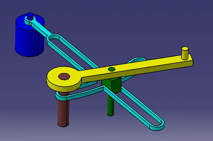
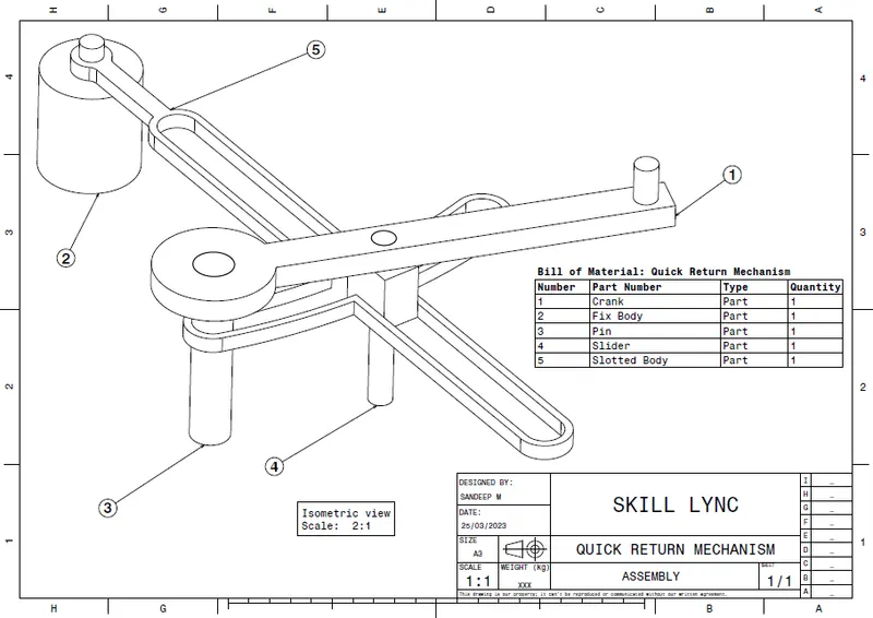
Quick Return Mechanism
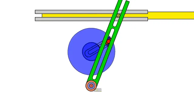
A quick return mechanism is an apparatus that converts circular motion into reciprocating motion. This mechanism is mostly used in shaping machines, slotting machines and in rotary internal combustion engines. The word quick return indicates that the returning stoke is faster than the forward stroke which help the tool to retrieve back faster after doing a particular job. Quick-return mechanisms feature different input durations for their working and return strokes. The time ratio of a Quick Return mechanism is the ratio of the change in input displacement during the working stroke to its change during the return stroke.
Applications
- It is used in the shaper Machine for flattening the workpiece.
- Same is used in the Slotter and Planer Machine.
- It is also used in the Screw press, Mechanical actuator, and Rotary combustion Internal Engine.
Advantages
- The process is automated.
- The construction of the mechanism is not complicated.
- It can perform operations like cutting, flattening, and slotting the workpiece.
- The idle time is reduced because of the fast returning stroke.
Dis Advantages
- In the returning stroke, there is no contact with the work so no cutting takes place hence the process takes much time to complete.
- The forward stroke takes much time compared to the return stroke.
- It takes more power to perform operations.
- There is friction between the slider and the Piston.
- Continuous it won’t work because of heat generated inside the piston and wear and tear can happen.
- Balancing of linkage is also a major problem as this device is also linked to linkages.
CV Joint
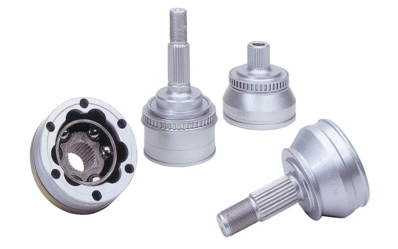
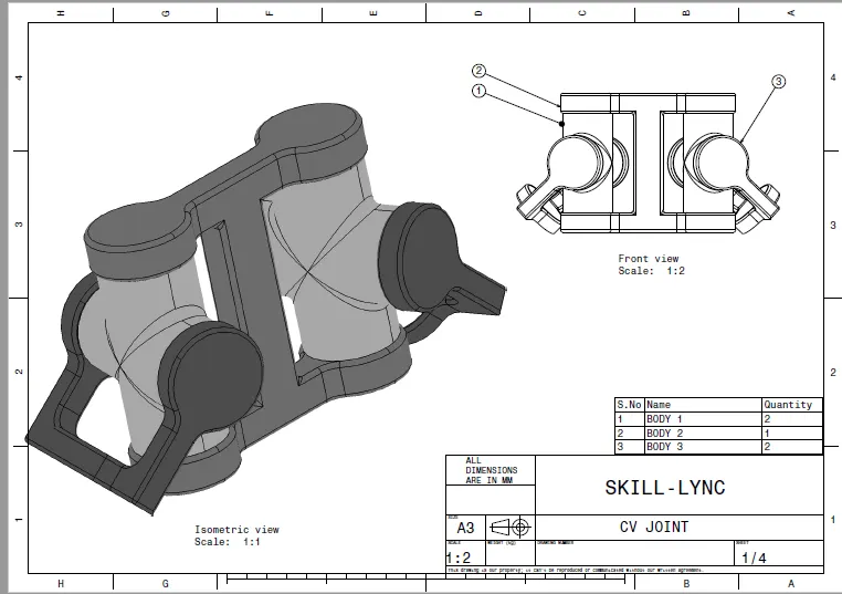
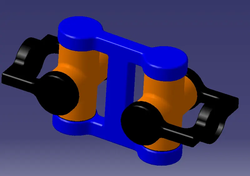
A constant-velocity joint (also called a CV joint) is a mechanical coupling which allows the shafts to rotate freely (without an appreciable increase in friction or backlash) as the angle between the two shafts moves within a certain range.
A common use of CV joints is in front wheel drive vehicles, where they are used to transfer the engine's power to the wheels, even as the angle of the driveshaft varies due to the operation of the suspension.
PROCEDURE
- Start
- Open catia in part workbench
- First create each part model as per given 2d drawings using Boolean method.
- Create 2d drawings in Draft workbench from newly created parts.
- Open Assembly workbench and import each and every parts by make use of Existing Component option.
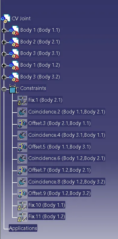
- After importing give Constraints as per the reference from drawing, in such a way that final assembly must be replica of given drawing.
- Save the file as .CATPRODUCT file.
- Create 2d drawings of the asmmebly in Draft workbench as save it as pdf
- Exit
SOFTWARE USED
Catia V5
CATIA DRAWINGS
Drawing 1: Quick Return Mechanism
Part Files
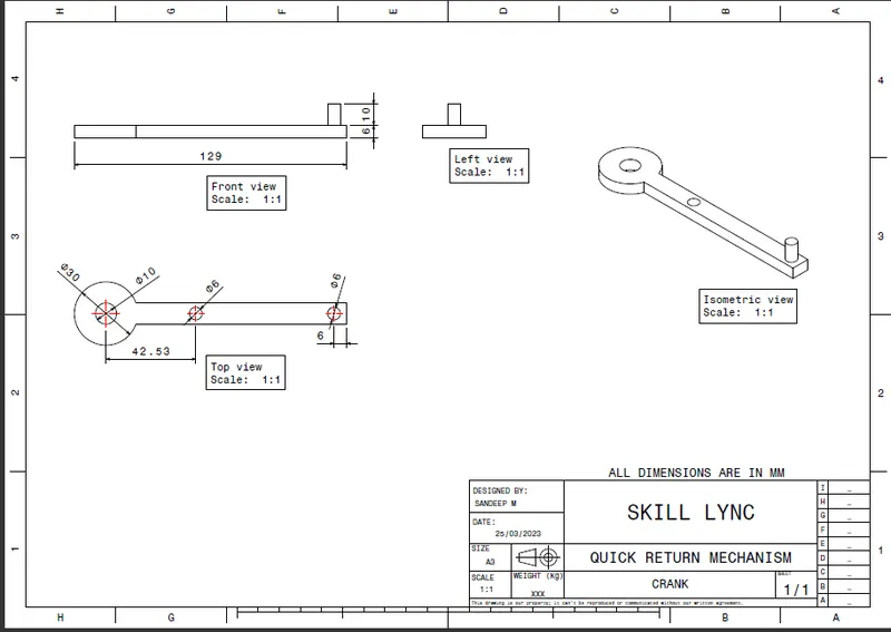
Crank
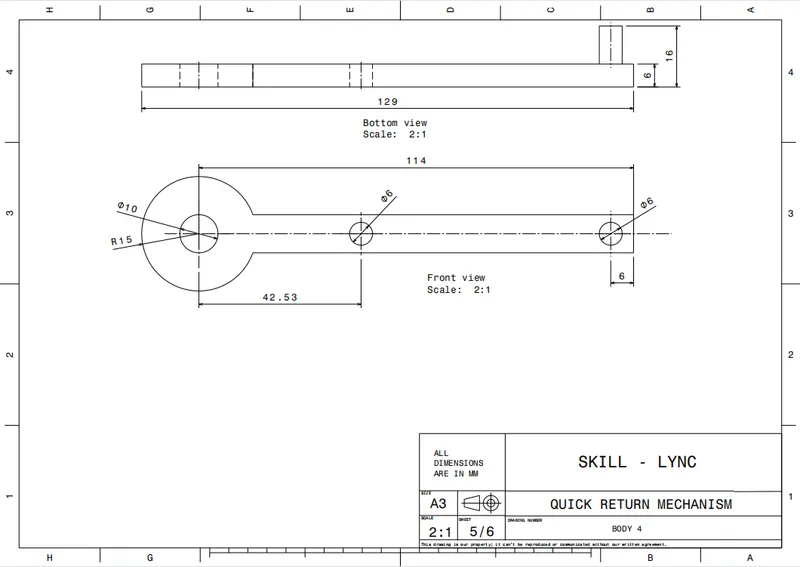
Master Sketch
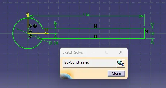
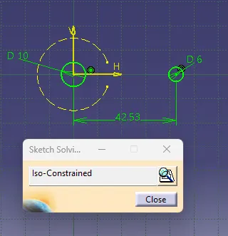
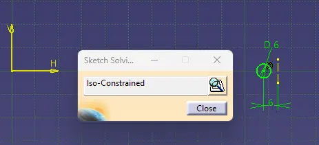
Fully Defined Sketch
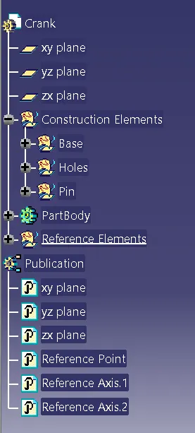
Tree Structure
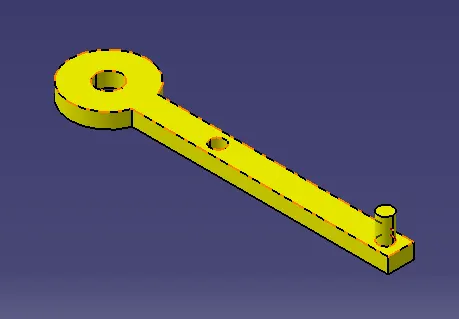
3D Part Model
2D Drafting
Fix Body
Master Sketch
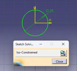
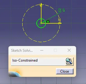
Fully Defined Sketch
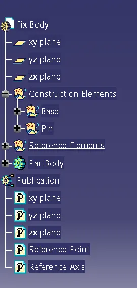
Tree Structure
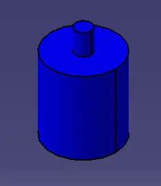
3D Part Model
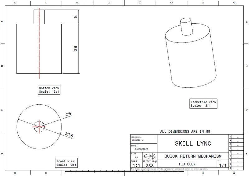
2D Drafting
Pin
Master Sketch
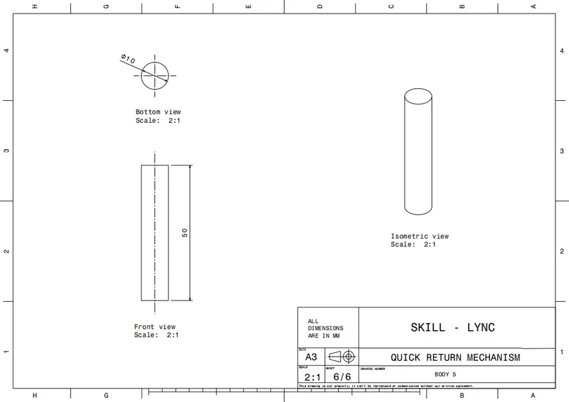
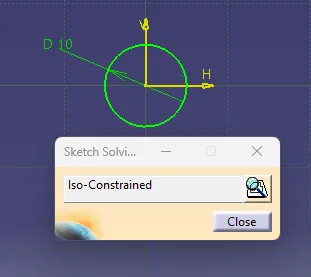
Fully Defined Sketch
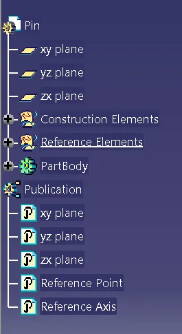
Tree Structure
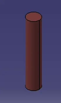
3D Part Model
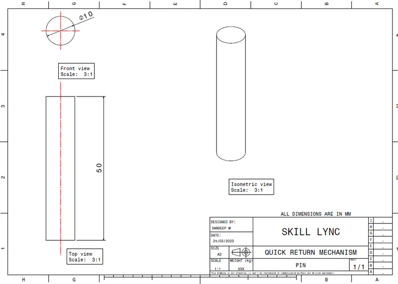
2D Drafting
Slider
Master Sketch
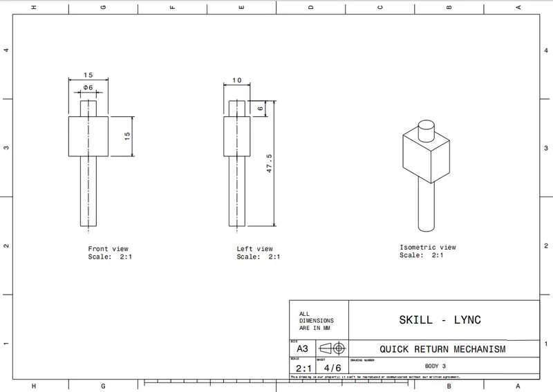
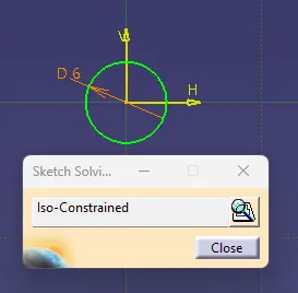
Fully Defined Sketch
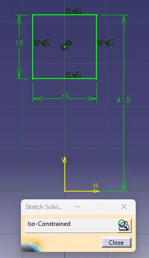
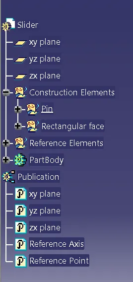
Tree Structure
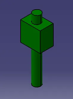
3D Part Model
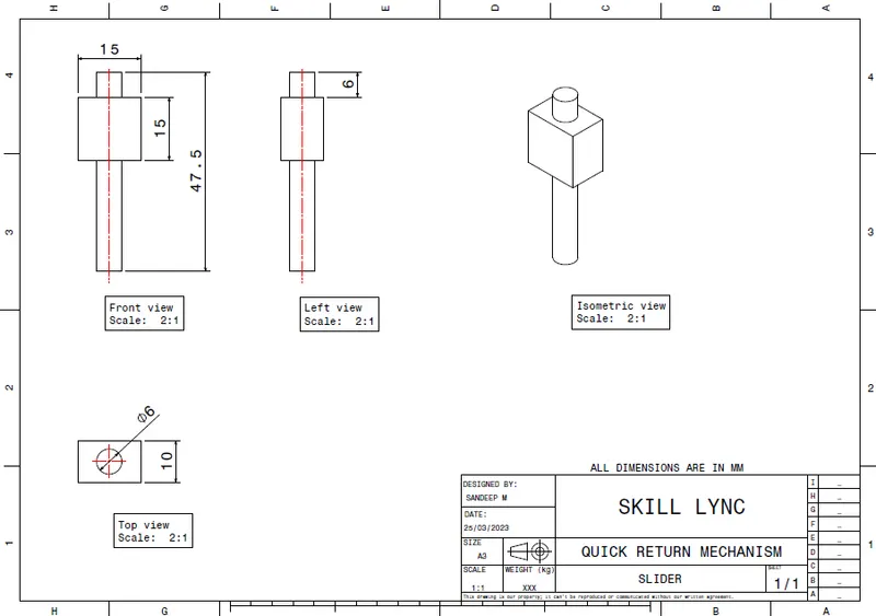
2D Drafting
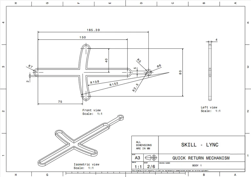
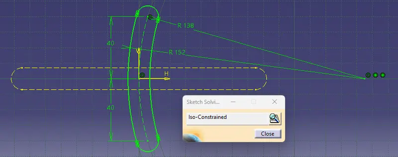
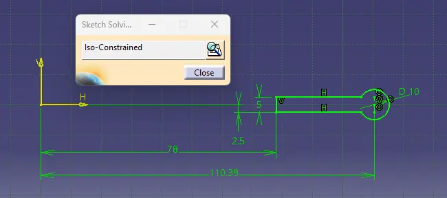
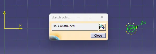
Slotted Body
Master Sketch
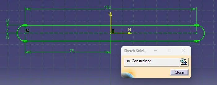
Fully Defined Sketch
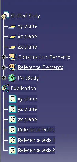
Tree Structure
3D Part Model
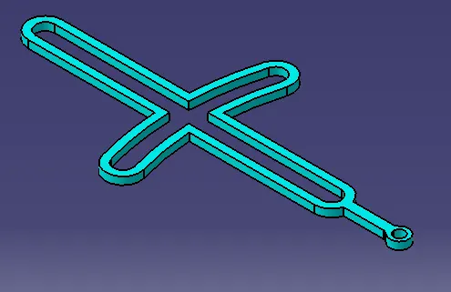
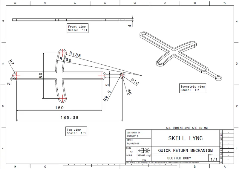
2D Drafting
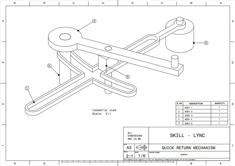
Assembly
Master Sketch
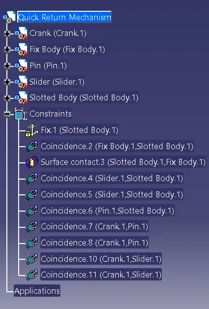
Tree Structure
3D Part Model
2D Drafting
Drawing 2: CV Joint
Part Files
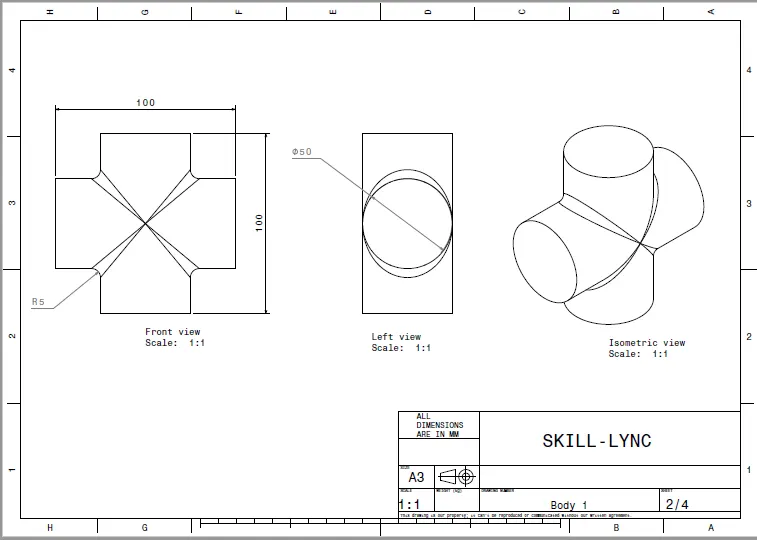
Body 1
Master Sketch
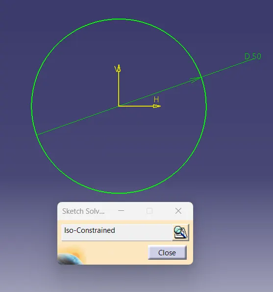
Fully Defined Sketch
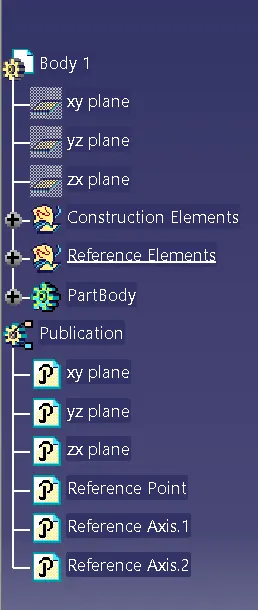
Tree Structure
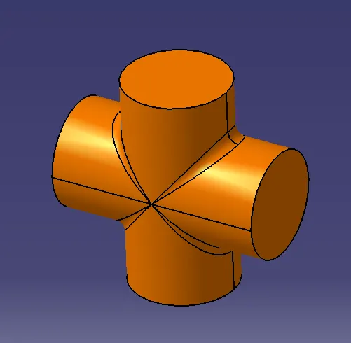
3D Part Model
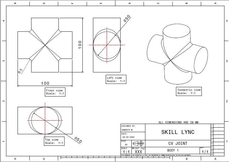
2D Drafting
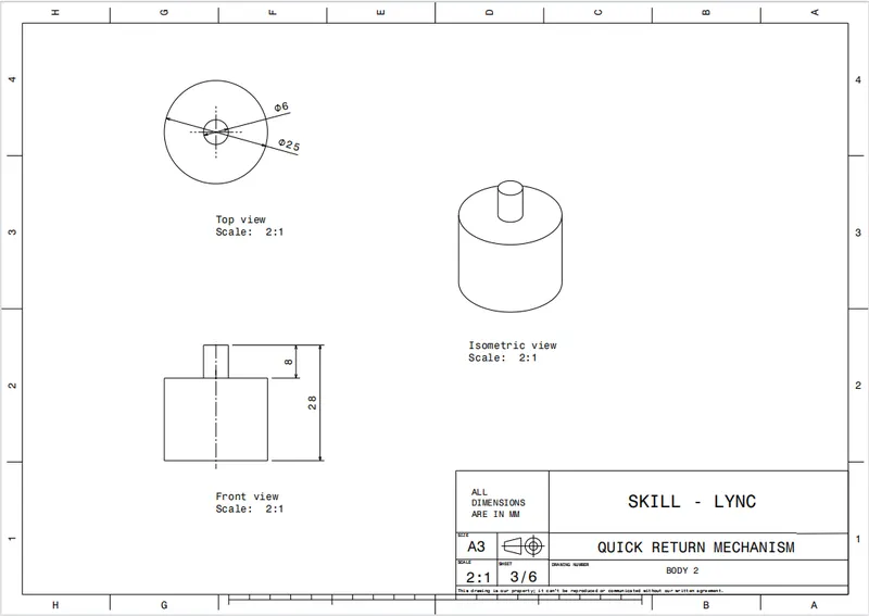
Body 2
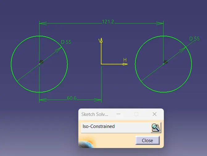
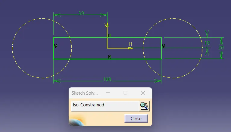
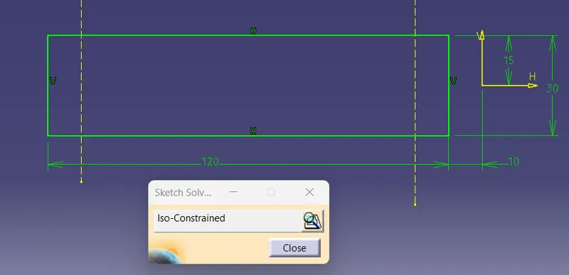
Master Sketch
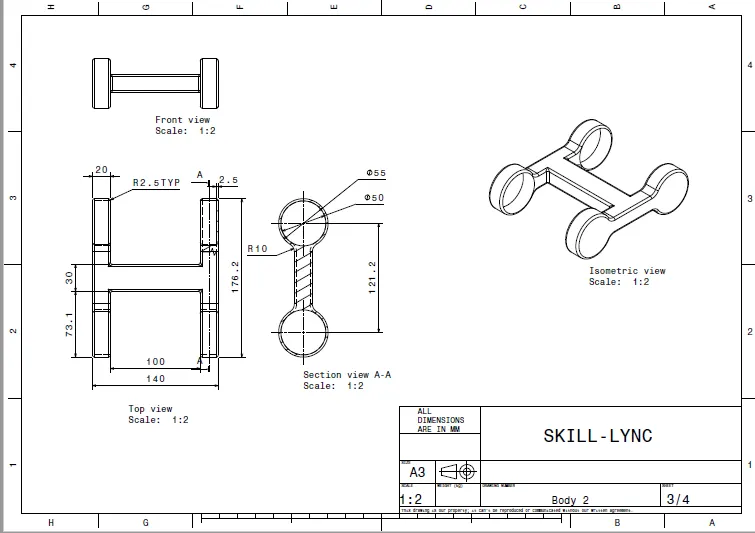
Fully Defined Sketch
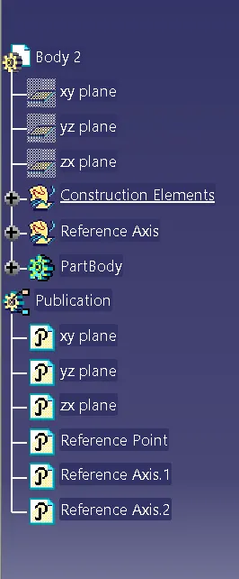
Tree Structure
3D Part Model
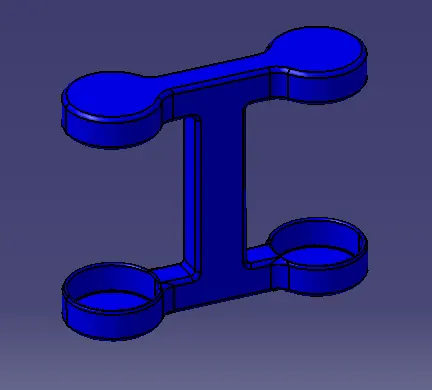
2D Drafting
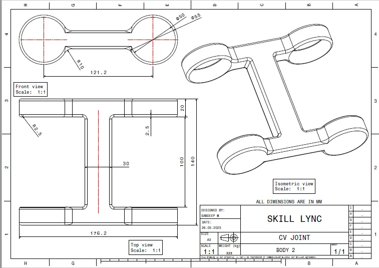
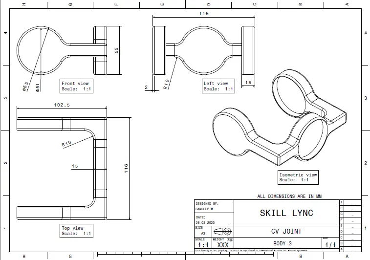
Body 3
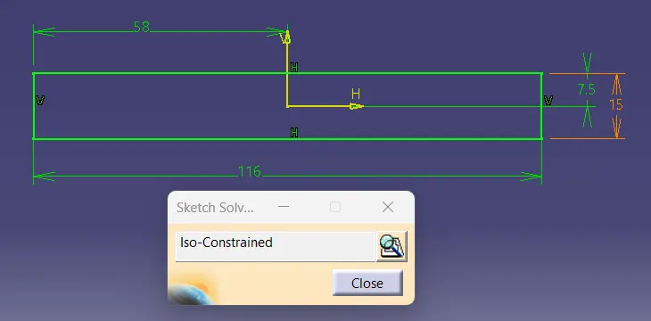
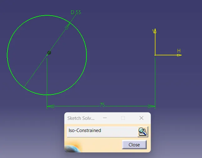
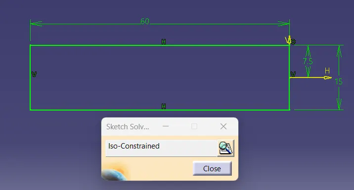
Master Sketch
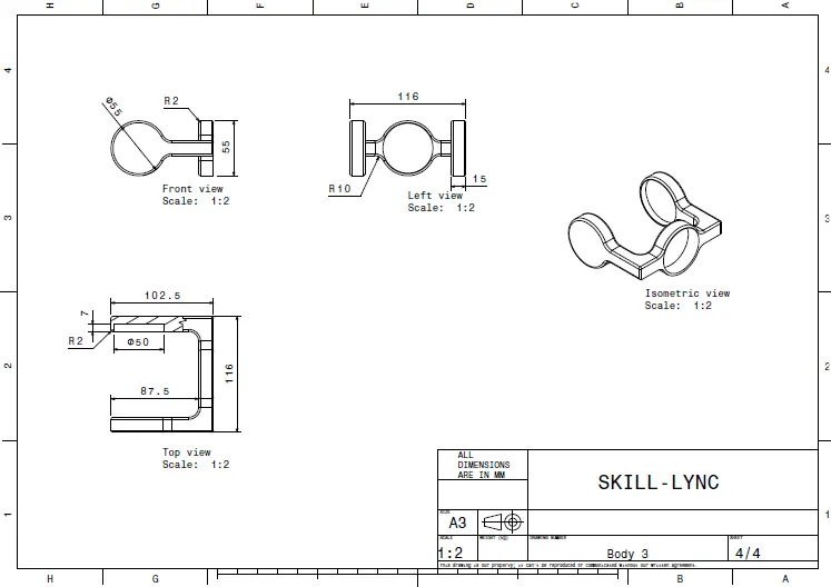
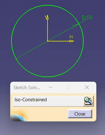
Fully Defined Sketch
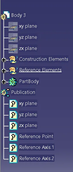
Tree Structure
3D Part Model
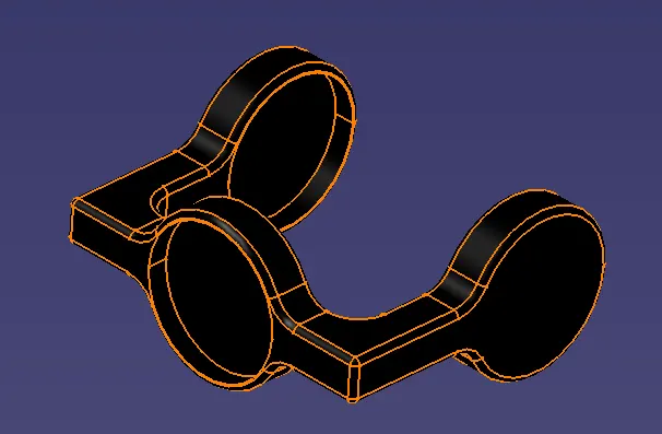
2D Drafting
Assembly
Master Sketch
Tree Structure
3D Part Model
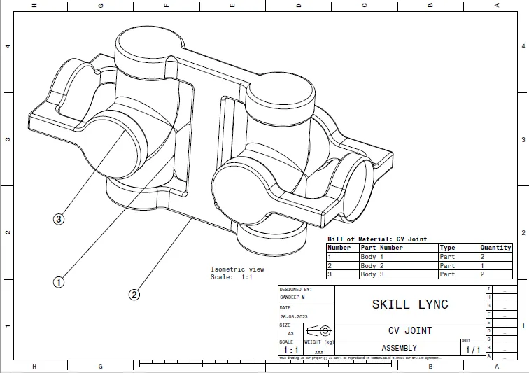
2D Drafting
CONCLUSION
Assemblies from the given 2D drawings have been created in Catia