Week 7 Challenge - Assembly Workbench
ASSEMBLY WORKBENCH
Objective:
Create the Quick Return Mechanism and Constanct Velocity Joint Assembly in CATIA Assembly Workbench.
Software Used:
CATIA V5.
Command Used:
Following commands used for creating sketch, Part and Assembly.
1. Following are the command used for creating 2D sketch in CATIA Sketch Workbench.
- Point
- Line
- Rectangle
- Circle
- Mirror
- Pattern
- Trim
- Corner
- Profile
2. Following are the command used for creating Geometric Constraint in CATIA Sketch Workbench.
- Symmetry
- Radius/Diameter
- Coincidence
- Offset
- Angle
- Length
- Tangency
- Cocentricity
- Parallelism
3. Following are the command used for creating Part in CATIA Part Workbench.
- Pad
- Edge Fillet
- Stiffner
- Mirror
- Pattern
- Multi-Pad
- Hole
4. Following are the command used for Assembly constraint in CATIA Assembly Workbench.
- Fix Component
- Coincidence Constraint
- Contact Constrint
- Offset Constarint
- Angle Constraint
Steps Followed For Creating Assembly in CATIA Assembly Workbench:
- Create the Sketch in Sketch Workbench using positioning sketch from the given diagram .
- All the sketch should be iso-constrained.
- Create the Part in Part Workbench from the sketch drawn in sketch workbench.
- Save all the created component part file in same folder.
- Open Product file in CATIA for Assembly.
- Drag all the part into Product file by copy it directly from the part file or using the option of existing component.
- Create skeleton Reference part file in product file and contraint it as fix componenet.
- Create reference element of all required part and publish it in tool to update all related file in case of any changes.
- Now assembly constraint the parts one by one as per required constraint.
- Save the created assembly file in same folder where part file are kept.
- After finishing it all, use drawing sketcher for creating 2D drafting of part and assembly.
ASSEMBLY
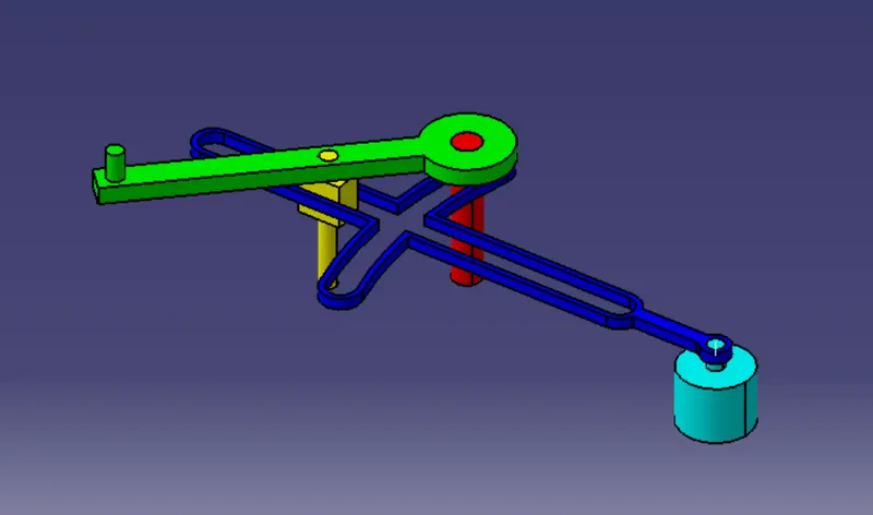
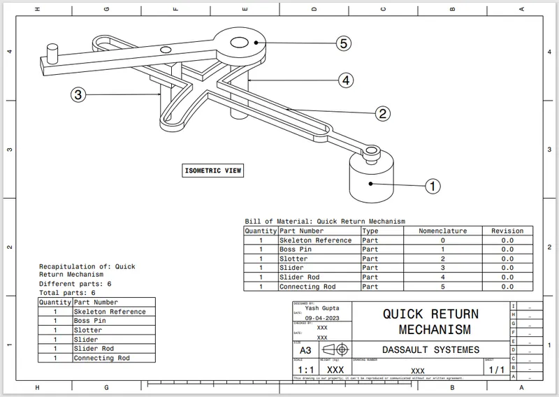
1. Quick Return Mechanism
Assembly of Quick Return Mechanism:
- Assembly
- Drawing
Parts of Quick Return Mechanism:
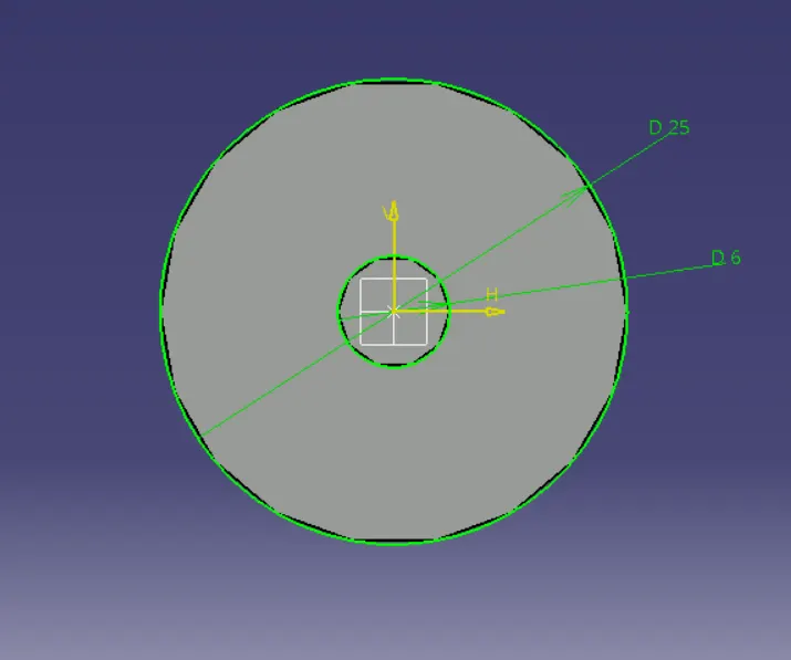
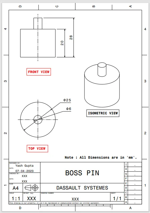
1. Boss Pin
- Sketch
- Part
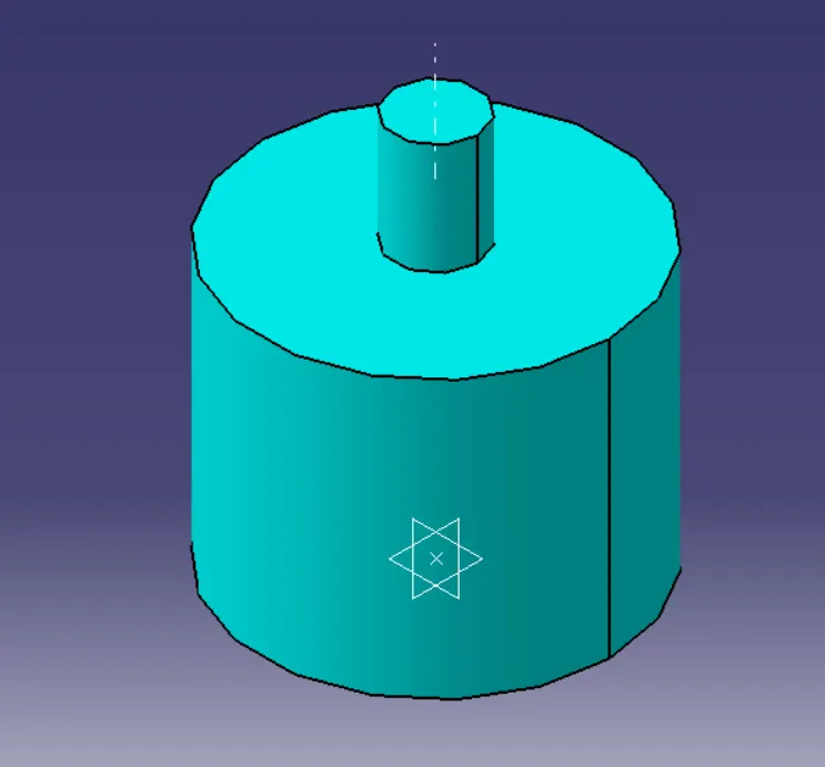
- Drawing
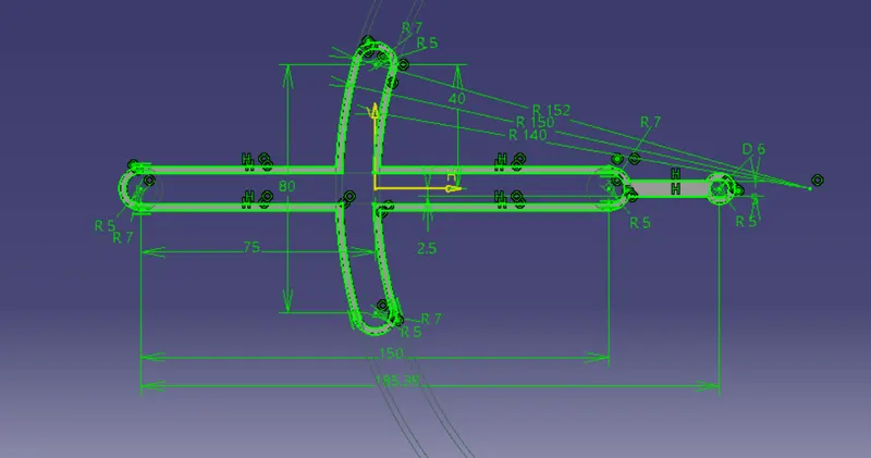
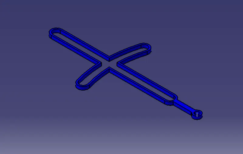
2. Slotter
- Sketch
- Part
- Drawing
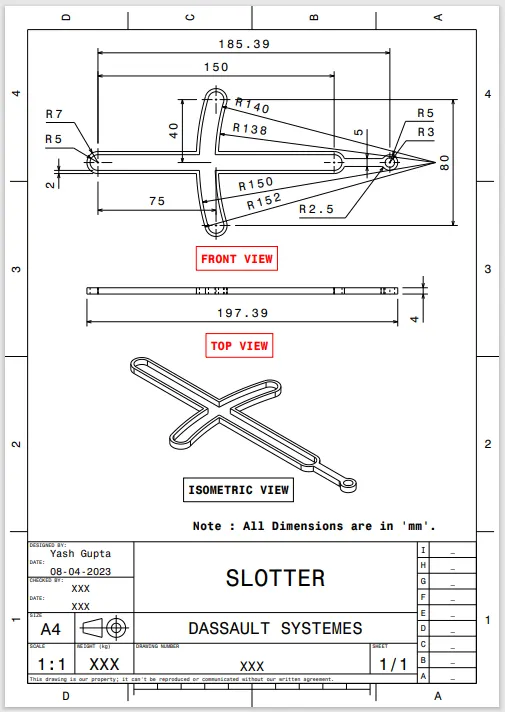
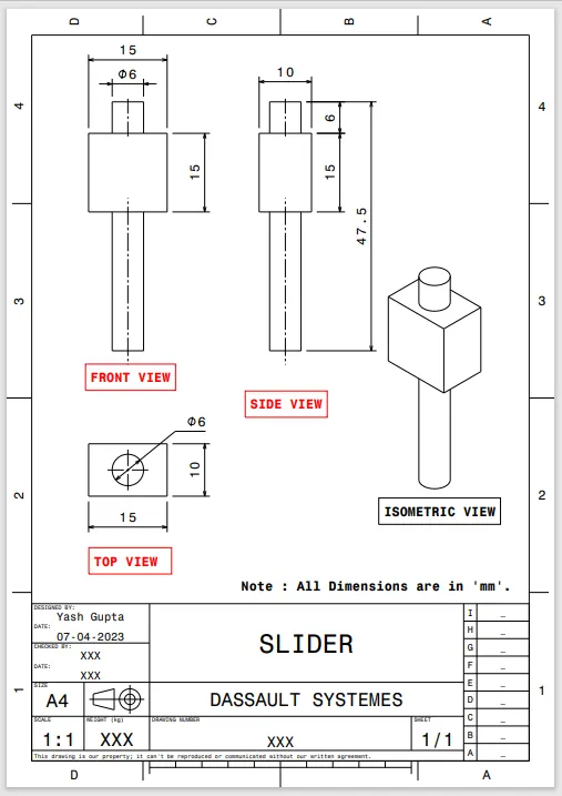
3. Slider
- Sketch 1
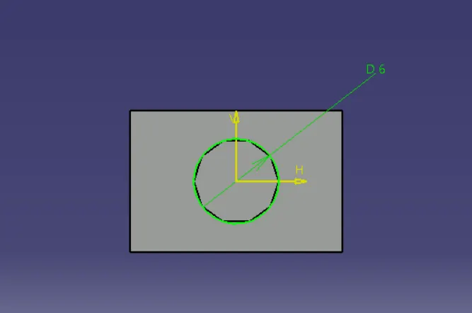
- Sketch 2
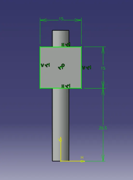
- Part
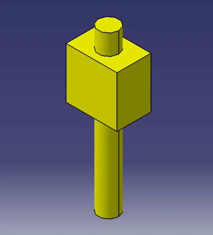
- Drawing
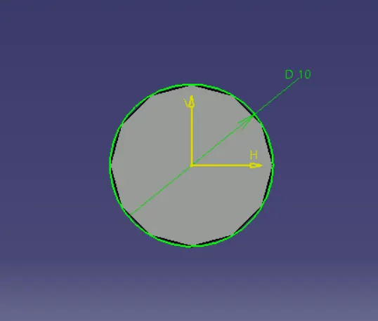
4. Slider Rod
- Sketch
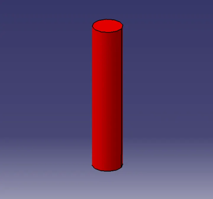
- Part
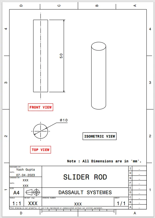
- Drawing
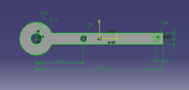
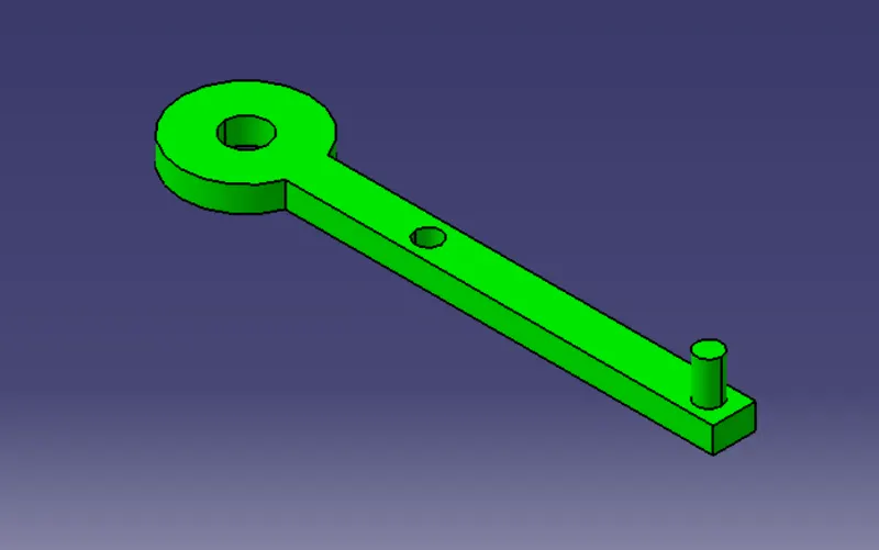
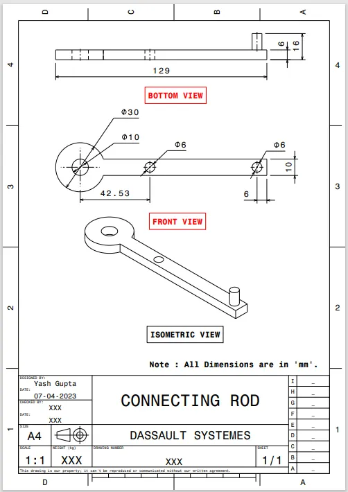
5. Connecting Rod
- Sketch
- Part
- Drawing
2. Constant-Velocity Joint
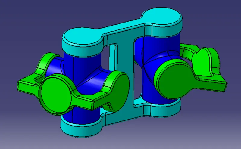
Assembly of Consatnt-Velocity Joint:
- Assembly
- Drawing
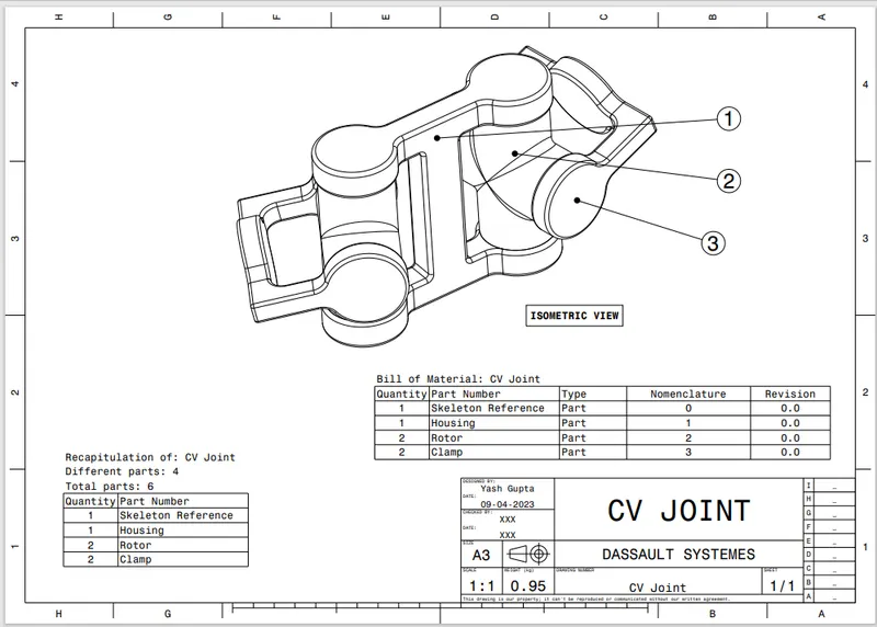
Parts of Constant-Velocity Joint:
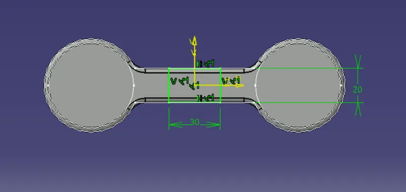
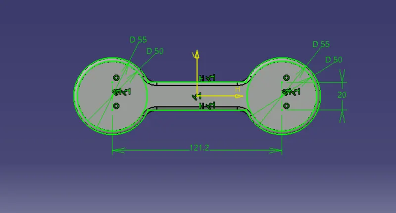
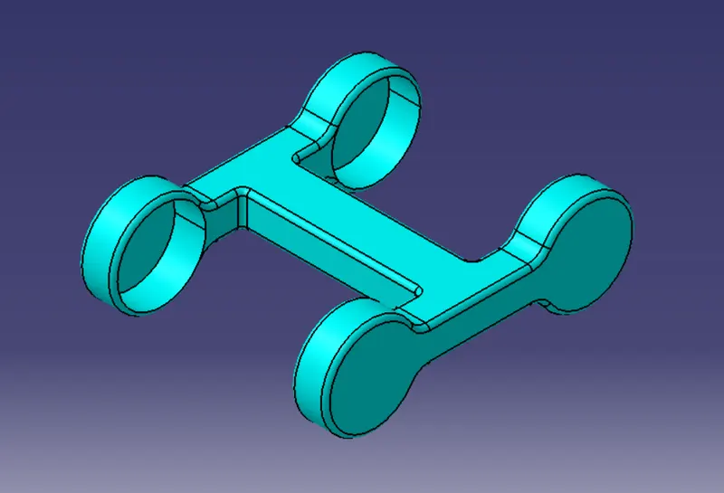
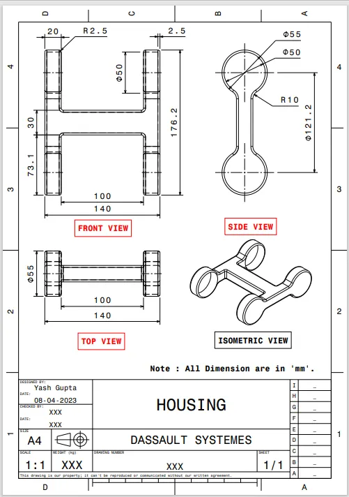
1. Housing
- Sketch 1
- Sketch 2
- Part
- Drawing
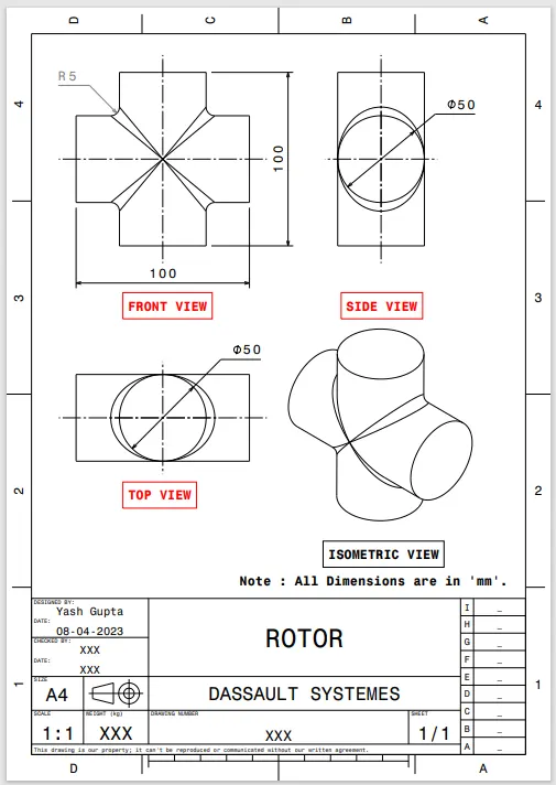
2. Rotor
- Sketch 1
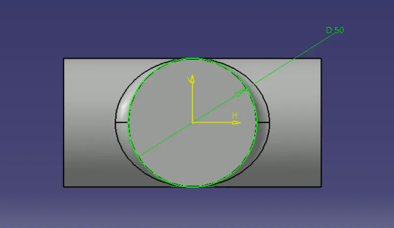
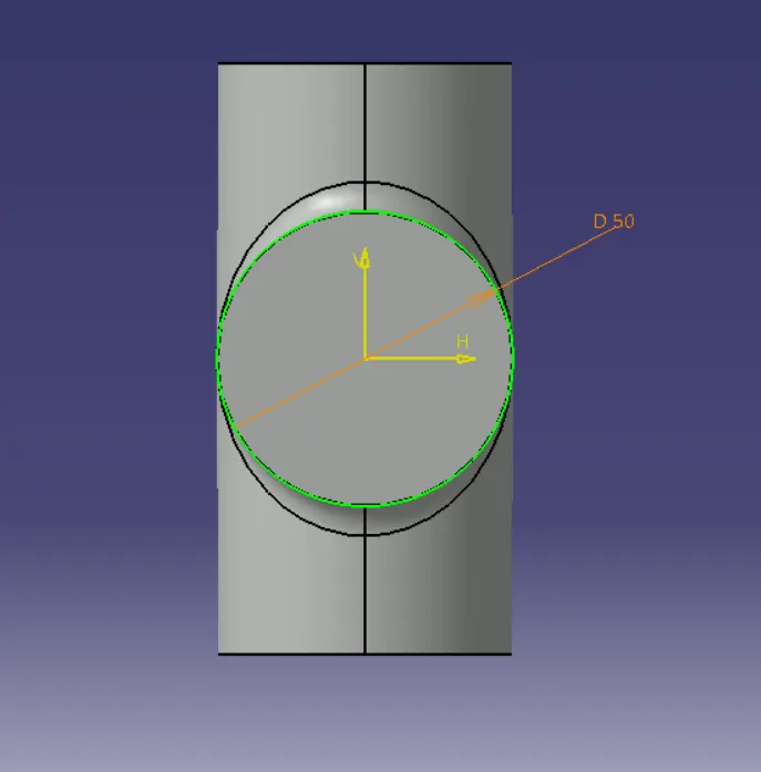
- Sketch 2
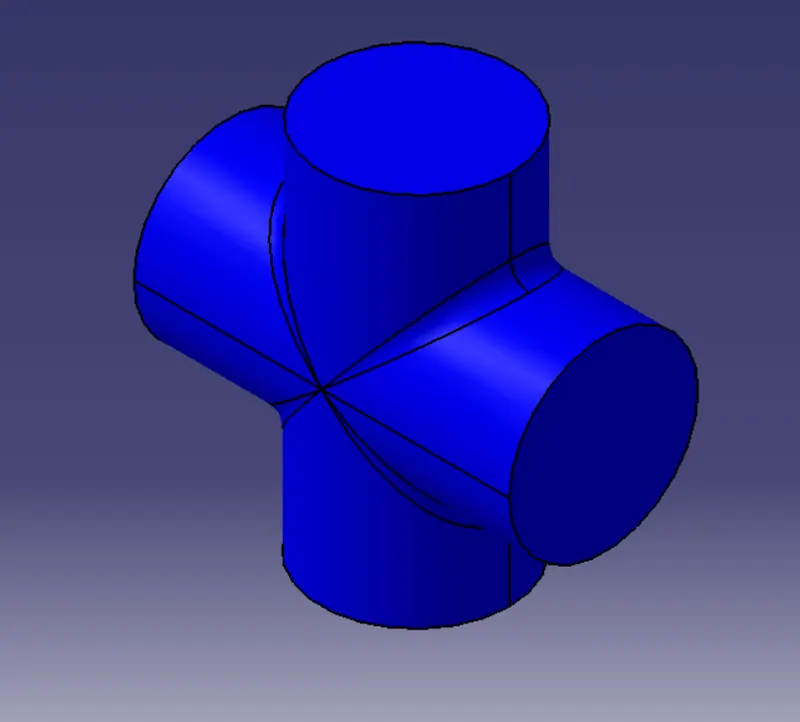
- Part
- Drawing
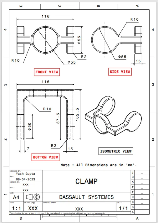
3. Clamp
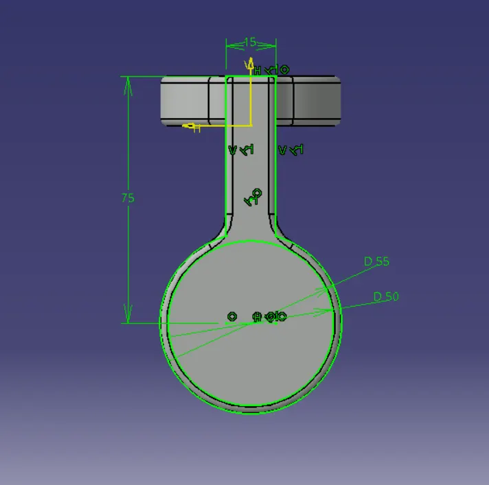
- Sketch 1
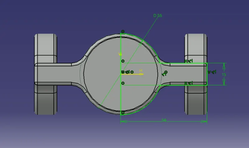
- Sketch 2
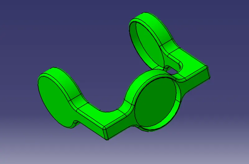
- Part
- Drawing