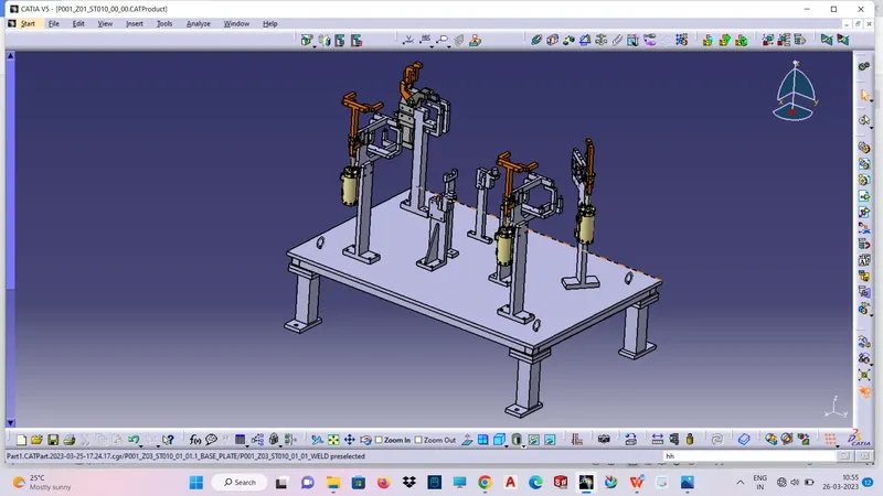
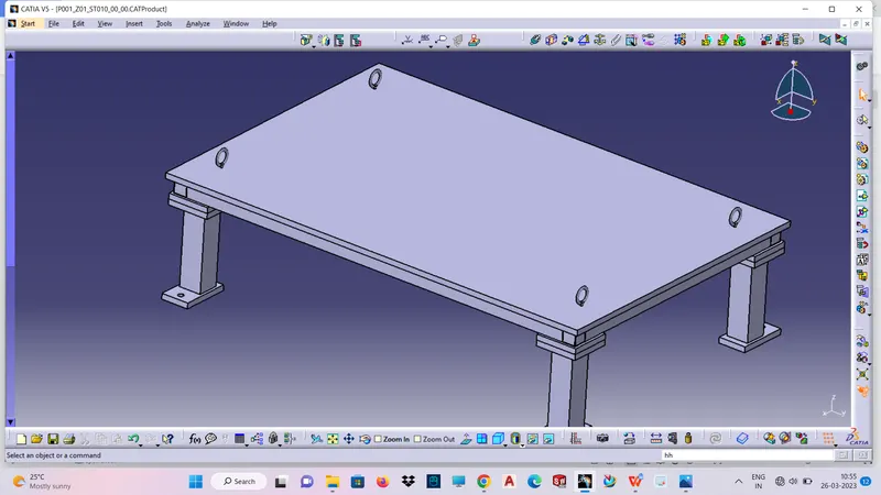
Week 7- Base Unit Design Challenges 2
AIM:
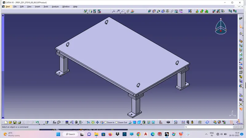
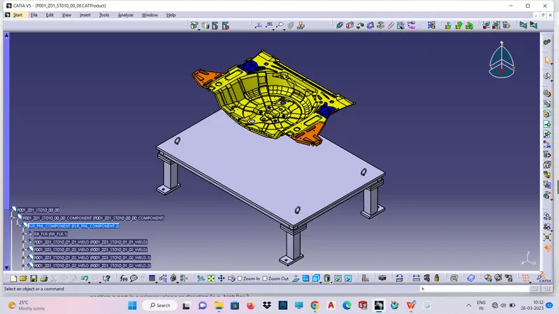
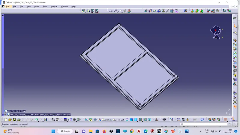
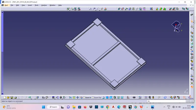
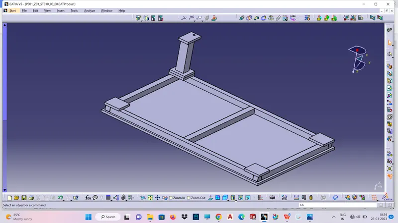
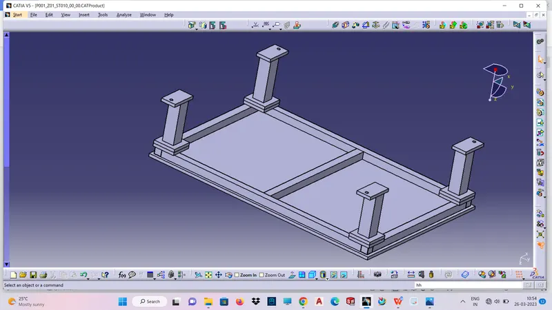
- Design a Base Unit for the units designed for the above challenges with all weldments for the given Car Panel.
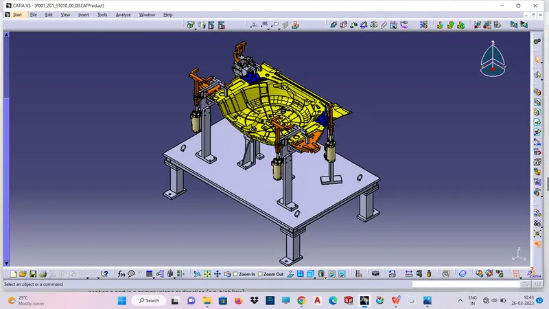
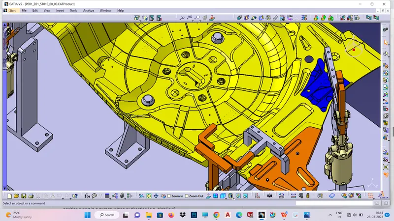
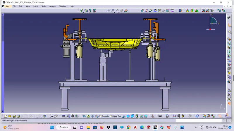
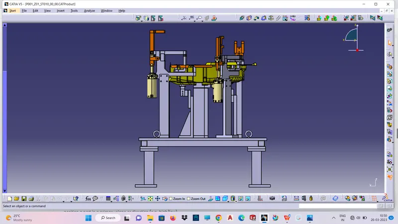
- Design the complete Fixture assembly (the units designed in the previous challenges can also be used). Make sure that all the 5 Panels given in the CAD data are fully constrained with the 3-2-1 principle.
BASE UNIT:
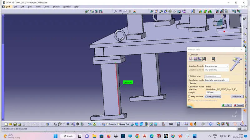
A base unit is the unit designed to mount all other units such as Clamp unit, pin unit, rest unit etc and also some other parts necessary like pneumatic valve box, trunking cable path will also be mounted on to a base unit. Base unit is the fundamental component of the fixture because all other components are mounted over it so every fixture have base unit. The base unit design is different according to the panel design of clamp system, location system etc.
Some components in base unit:
- Base plate.
- Trunking channel.
- Valve box.
- Eye bolt.
- Floor plate.
The important parameters to be considered while designing base unit:
- Thickness of base plate.
- Trunking channel shape and size.
- Eye bolt size.
- Leg heigh with respect to working height.
Constrained with the 3-2-1 principle:
3 - Locators/Supporters.
2 - Locating pins.
1 - clamp unit.
The 3-2-1 principle
- The 3-2-1 principle of location (six point location principle) is used to constrain the movement of workpiece along the three axes XX, YY, and ZZ. This is achieved by providing six locating points, 3 pins in base plate, 2 pins in vertical plane and 1 pin in a plane which is perpendicular to first two planes.
Locating a part to be machined involves mainly three steps: Supporting, Positioning, and Clamping.
Two main intentions when placing a job on a jig/fixture are:
Precisely positioning the part at the desired coordinates.
Curbing all six degrees of movement so that the part cannot budge.
An extensively used method for obtaining these objectives is the 3-2-1 principle or six degrees of freedom for part location.
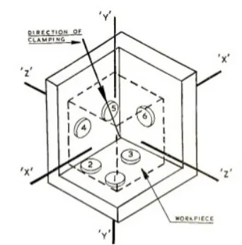
The 3-2-1 method is a work-holding principle where three pins are located on the 1st principle plane, i.e., either XY, YZ, ZX. And two pins are located on the 2nd plane perpendicular to the 1st plane, and at last, one pin on the plane is mutually perpendicular to the 1st and 2nd planes. The aim is to constrain the movement of the workpiece along all three axes.