Week 7- Base Unit Design Challenges 2
Base Unit Design
AIM:
- To design a Base Unit for the aready units designed with all weldments for the given Car Panel.
- To design the complete Fixture assembly.
Introduction:
Base unit is the unit designed to mount all theother units such as fix pin unit, clamp unit, rest unit extc., of the tool also the other parts necessary for a tool like pneumatic valve box, trunking cable path will also be mounted on the baes unit.
Base unit is the fundamental component of the fixture because all other components are mounted over its so every fixture have base unit . The base unit design is different accordign to the panel.Design of clamp system ,location system etc.
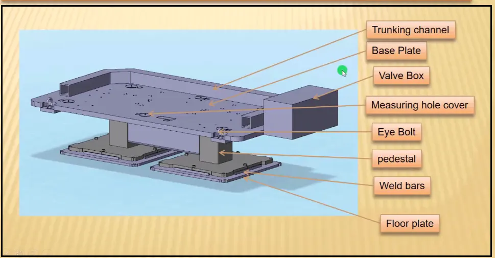
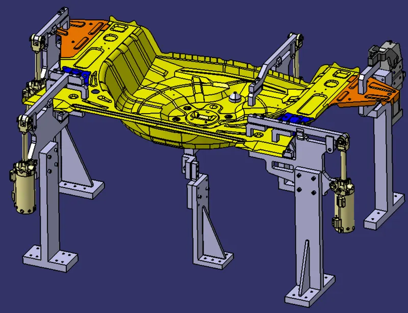
The above image shows somw important parts of the base unit design and some are discussed below,
- Trunking channel:
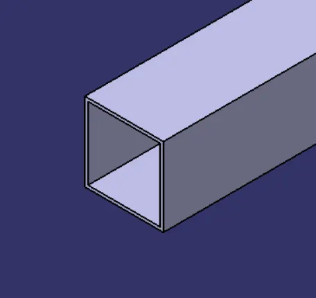
Trunking channel is a basically duct which accomodates all the pneumatic and electrical hoses and wires for the unit. It protects the wires / cables from damage.
- Base plate:
Base plate is a machined plate of 25 to 40mm thickness made of steel and aluminium, on to which the holes are drilled to mount the individual units like clamp unit, pin unit etc.,
- Pedestal:
It is a component which connects the base plate to the floor plate. Pedestal is a standard part in general and it can be welded to the base plate.
- Floor plates:
Floor plate is grouted to the floor with fixed bolt on the ground. Floor plates are also called as foundation plates.
- Eye bolt:
An eye bolt is a bolt with a loop at one end. They are used to firmly attach a securing eye to a structure, so that ropes or cables may then be tied to it inrder to lift the unit. The eye bolt should be placed such that it does not harm clamp / pin units.
Design principle:
Theoretically, the important principle used in the design of BIW fixture assembly is 3-2-1 principle.
A workpiece will be completely confined when blanked against:
- 3 points in one plane: The “3” in 3-2-1 refers to 3 locators (passive fixture elements) on the primary locating/datum surface.
- 2 points in another plane: The “2” in 3-2-1 refers to 2 locators on the secondary locating/datum surface.
- 1 point in a third plane: The “1” in 3-2-1 refers to 1 locator on the tertiary locating/datum surface
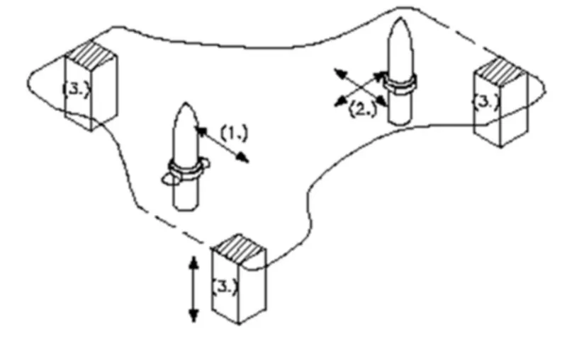
In this project 5 plates have to be fully contrained. Therefore as per 321 principle only 1 clamp and 2 pin units are required with restricts the movement in all direction.
Procedure:
- First the neccesary file are downloaded such as car panel assembly.
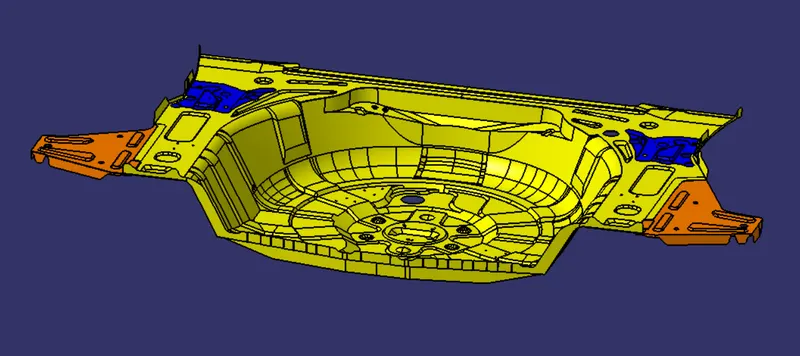
Now the already designed pin unit, clamp unit are imported and adjusted at appropriate place where required in order to constrain the above car panel in every posible directions / ways.
List of Standard parts:
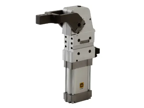
- Pneumatic Clamp unit: V_50_1_BR3_A40_T12_TUENKERS.
Clamp cylinders are bought out parts. Some of the manufactures are Tunkers, Zytran, Destaco, Festa, Steel smith.
Clamp cylinders are generally 40, 50, 63, & 80 bore capacity
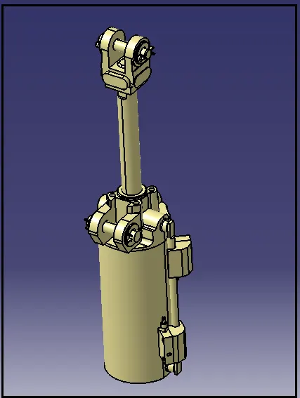
-
CKG1: Series of cylinder
B: Clevis width as 19.5 mm.
63: Bore size
100: Stroke of cylinder
Y: End bracket i.e. double knuckle joint (M6 without tap).
In this design the hole diameter is 8mm simple as well as threaded. The hexagonal socket type head screw of diameter 8mm of required length wherever necessary.
Next is to design the Base plate. Before designing below fundamentals are taken into consideration:
- A base plate size should cover all the units with its outer periphery including the opening.
- A base plate is always preferred to be designed with respect to BCS Coordinates.
- A base plate should be drilled with datum holes/ measuring holes in line with a pitch of 1000 m in general.
- The number of datum holes depend on the size of the base plate.
In this project the size of the base plate is 1275mm x 1425mm x 20mm as shown in below image.
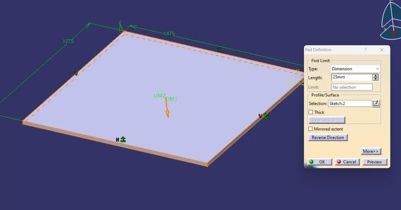
Threaded holes are created as per the position of the units to be mounted.
Now taking bottom face of the base plate as reference the trunking channel is designed. Channel should is inside the side surface of the base plate, here in this case is 15mm.
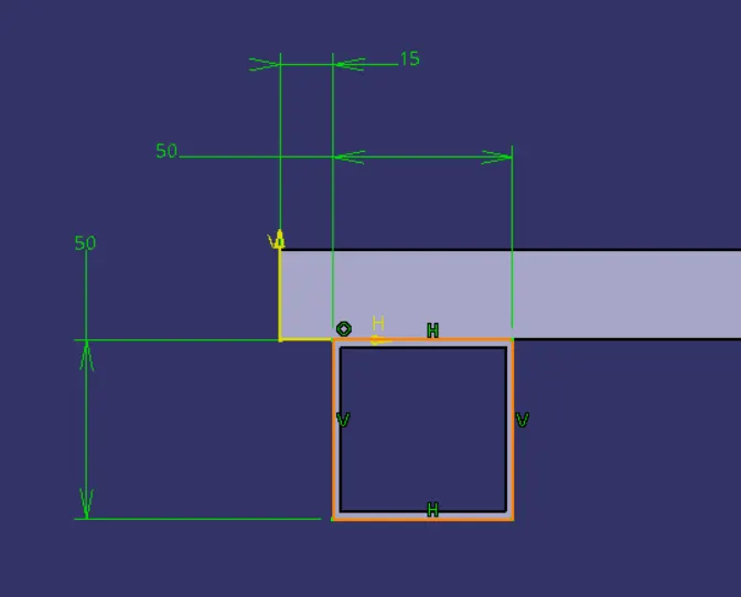
The arrangement of the trunking channel depends on the crossection of the rectangular base plate.
The rectangualr arrangement is same for al but the additional channel in the middle is used only according to requirement and applications.
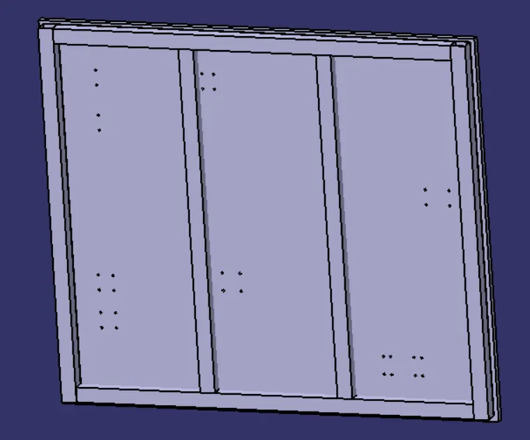
The base plate, trunking channel and a plate should be welded together ans saved a seperate assembly.
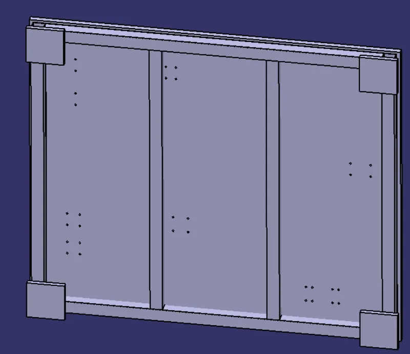
The height of the pedestal is decided such that the working surface comes to a height of 900-1100mm. This height is needed for ergonomic purpose, as the operator needs to operate at a safe height which can cause less fatigue.
The pedestal and the floor plate is saved under other assmebly.
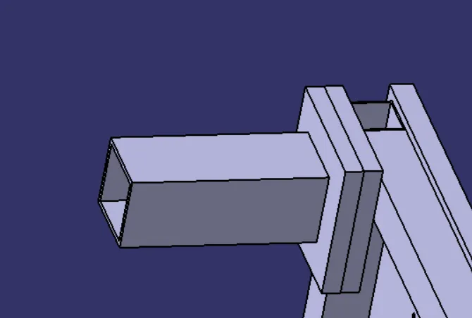
The number of pedestals required is depended on the load carried by it. In this project four pedestal are designed each at the four corners.
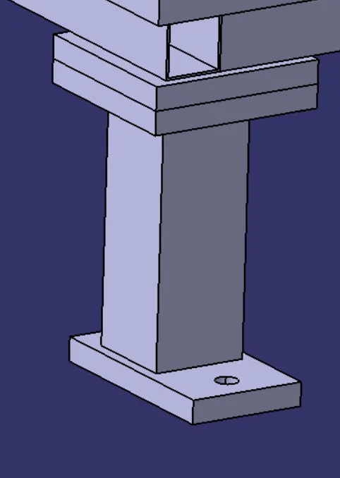
A threaded hole of M22 is proved to each floor plate to attached the complete fixture to the floor.
Assembly:
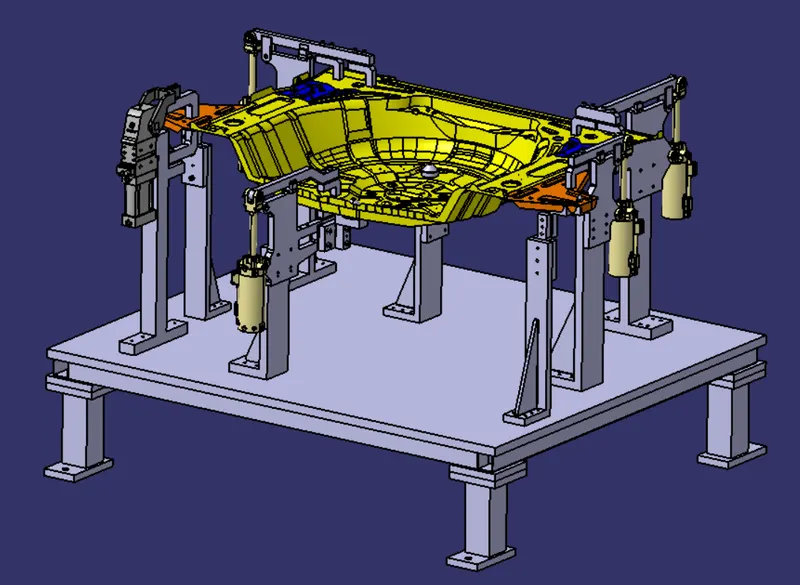
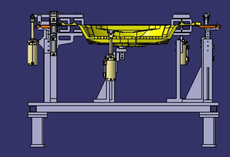
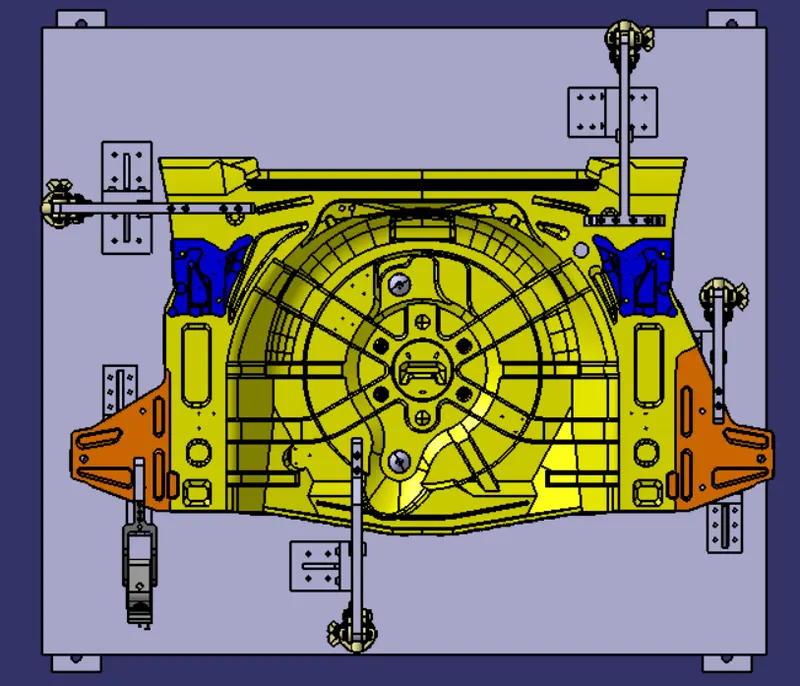
The below images are the final assembly of the base unit design along with necessary clamp and pin units.
Isometric View:
Front and bottom view:
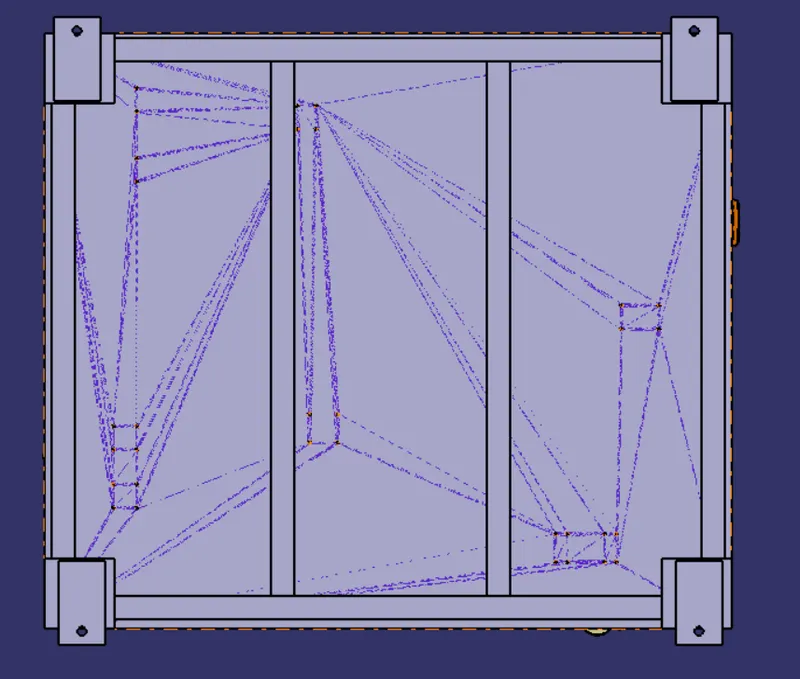
Top view:
Conclusion:
As per the objective the base unit is designed completely with all necessary components. the fixture units are arranged in such a way the the car panel is constrained in all directions accordindly.