Week 7- Base Unit Design Challenges 2
AIM: To design a Base Unit with complete fixture assembly.
BASE UNIT:
A base unit is the unit designed to mount all the other units (Clamp unit, Pin unit, rest unit etc ., ) of the tool, also other parts necessary for a tool like pneumatic valve box, trunking cable path will also be mounted on to a base unit.
The parts of a base unit are:
Base Plate: Base plate is a machined plate of 25 to 40mm thickness made of steel and aluminium, on to which the holes are drilled to mount the individual units like clamp unit, pin unit etc ., of a tool.
Pedestal:
- A pedestal is a part which connects the base plate to the floor plate.
- A pedestal is a standard part in general, and in some cases it can be a welded frame integrated with the base plate.
- A standard pedestal can be of different height and different sizes.
- Depends on the size of the base plate, the number of pedestal varies for load distribution
- A pedestal are of different types with different inclinations.
Trunking Channel: A trunking channel is a duct which accommodates all the pneumatic and electrical hoses and wires for the units of the tool.
Valve Box: Valve box is a standard part which will accommodates the pneumatic valves for the units.
Eye Bolt: Eye bolts are used for the transporting of the tool, using lift hooks, Fork lift holes will also be provided in some cases for transporting purpose.
Floor plate:
- Floor plate is grouted to the floor with fixed bolt on the ground.Floor plates are also called as foundation plates.
- There will be a clearance of 10mm maintained between the pedestal base plate and the floor plate.
- This clearance will be used by the levelling screws, for levelling the entire tool.
- Weld bars are be used to weld the positions permanently, after levelling is done.
- A weld bar is a plate along the sides of the base plate of the pedestal.
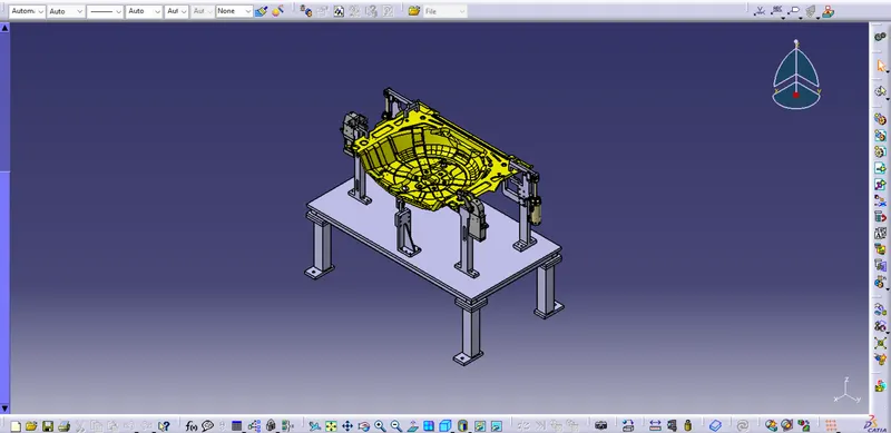
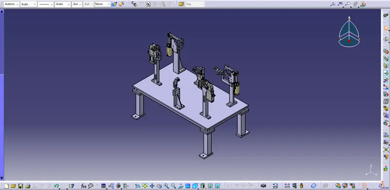
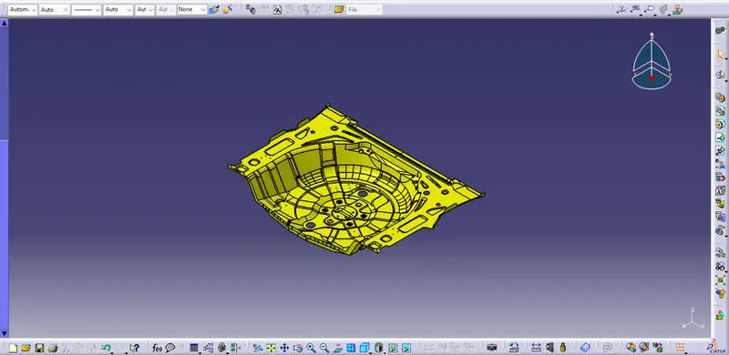
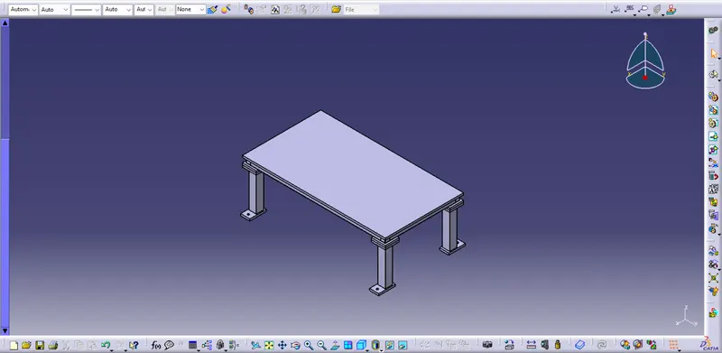
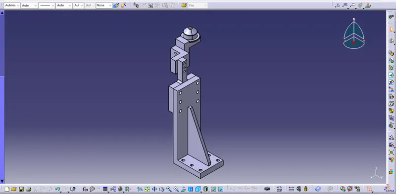
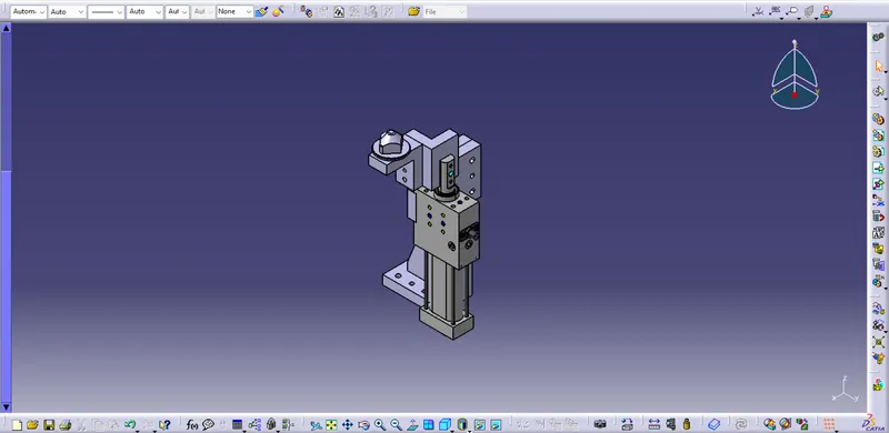
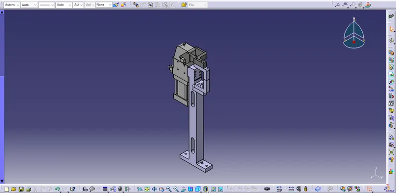
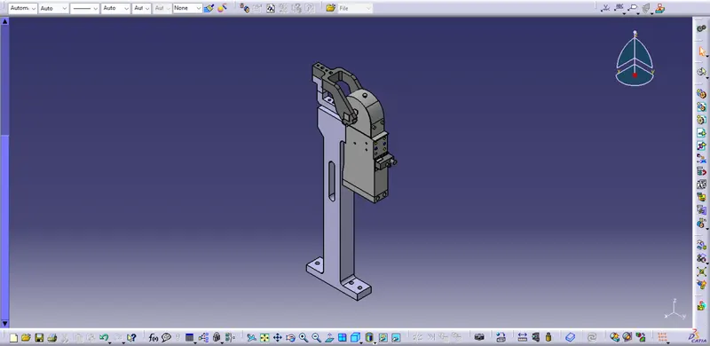
Design methodologies followed to design the Base Unit:
- Launch the CATIA V5 application and create new product file as (P003_Z03_ST03_00_00)
- Create another two product files into the main product file as (P003_Z03_ST03_00_00_COMPONENT) & (P003_Z03_ST03_01_00_BASE_UNIT)
- Into the (P003_Z03_ST03_00_00_COMPONENT) product file add the car panel part file
- Into the (P003_Z03_ST03_01_00_BASE_UNIT) product file create another product file as (P003_Z03_ST03_01_01_WELD_FRAME) for weld frame
- Into the (P003_Z03_ST03_01_01_WELD_FRAME) product file create part files for plates,base plate & square tube
- Sketch the profile for base plate with dimension 1550×850 and pad it for 20mm
- Sketch 50×50 square profile for square tube and pad it for length 810 with 2mm thickness
- Sketch another 50×50 square profile for square tube and pad it for length 1510 with 2mm thickness
- Sketch 150×150 square profile for plate and pad it for 20mm
- Create 4 instances of plate using multi instantiation
- Into the (P003_Z03_ST03_01_00_BASE_UNIT) product file create another product file as (P003_Z03_ST03_01_02_WELD_FRAME) for weld frame
- Into the (P003_Z03_ST03_01_02_WELD_FRAME) product file create part files for plates,floor plate & pedestal
- Sketch 150×150 square profile for plate and pad it for 20mm
- Sketch 80×80 square profile for pedestal and pad it for length 400 with 5mm thickness
- Sketch 180×150 rectangular profile for floor plate and pad it for 20mm
- Create M24 hole in floor plate
- Add other fixture units like (pin unit,clamp unit,pin clamp unit) into the main product file
- Allign all the units accurately on the base plate
- Make sure the car panel is fully constrained with the 3-2-1 principle.