Week 7:- Base Unit Design Challenges 1
1. Base unit is the unit designed to mount all the other units (clamp unit, pin unit, rest unit etc..) of the tool, also other parts necessary for a tool like pneumatic valve box, trunking cable path will also be mounted on to a base unit.
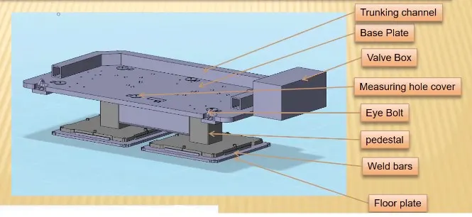
Typical parts of Base units :-
Base plate:- Base plate is a machined plate of 25 to 40mm thickness made of steel and aluminium , on which the holes are drilled to mount the individual units like clamp unit, pin unit,etc., of a tool.
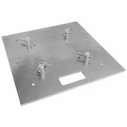
Pedestal: A pedestal is a part which connects the base plate to the floor plate. A pedestal is a standard part in general , and in some cases it can be a welded frame integrated with the base plate.
- A standar pedestal can be of different height and different sizes.
- Depends on the size of the base plate, the number of pedestal varies for load distribution.
- A pedestal are of different types with different inclinations.
Trunking channel: A trunking channel is a duct which accomodates all the pneumatic and electrical hoses and wires for the units of the tool.
Valve Box: Valve box is a standard part which will accomodates the pneumatic valves for the units.
Eye Bolt: Eye bolts are used for the transporting of the tool, using lift hooks, Fork lift holes will also be provided in some cases for transporting purpose.
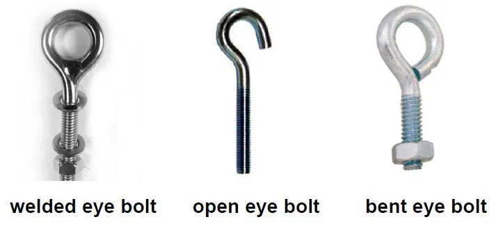
Floor Plate: Flooe plate is grouted to the floor with fixed bolt on the ground. Floor plates are also called as foundation plates.
- There will be a clearance of 10mm maintained between the pedestal base plate and the floor plate.
- This clearance will be used by levelling screws, for levelling the entire tool.
- Weld bars are be used to weld the positions permanently, After levelling is done.
- A weld bar is a plate along the sides of the base plate of the pedestal.
Weld bars: These bars are used to position the fixture. Weld bar is steel plate placed along side of base plate of pedestal.
2. The points need to account while designing a Base Unit as below:
- Working Height: it is depend upon type of operation whether it is manual welding or robotic welding height of base unit decided. For manual welding fixture working height must be 850 to 1100mm for ease in welding operation for the operator.
- Selection of Eyebolt depend upon weight of fixture. According to the weight of fixture tapping for eyebolt is provided on base plate like M24 or M20. Generally four eyebolt are provided on base plate.
- Depending on no of units, sizes and weight base are designed. base designed are made up of square or rectangular tubes or c channels with machined plate.
- Generally four dowel holes are provide at four corner of base plate with its coordinates displayed on aluminium plate
- Base unit is designed in such a way that there is mon possibility of deflection vibration.
3.Dump Unit is the complex unit to design due to space constains there is less space avilable & have to adjust all the parts in available space. It consist of dump cylinder to perform the operation of clamping & unclamping car panel.
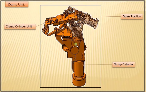
- To restrict the motion and ensure the proper resting of the panel being welded
- To ensure there are no rotation in the panel
- To ensure there is enough clamping force in the cyliinders so that it doesn't while welding
- Dump unit should be perfect shimming for adjustment of the panel.
4. The points considered while designing the dump unit.
- 3-2-1 principle: This is a basic principle while designing any fixture used to locate any car panel in fixture proper.
- Mass Consideration: Weight of dump unit must be at least side. Less the weight of unit less will be the force required to operate this unit. While taking such consideration of mass strength will be at maximum side.
- Time of opening and closing: It is one of the important point which is considered while designing such unit. Cylinder is selected such that it is able to take load of unit while operation.
- Open conditioon: It is one of the basic point which is considered in every mounting until like movable pin unit ot clamp unit ot slider unit.
5. Slide Unit are used at places where there are space constraints and places where there is less accessibility. Sometimes, there are too many small panels near each other and there is not enough space as each panel requires resting, location using 2 pins, clamping and sensing.
Classification of Slide Unit:
According to the guide ways used
1. Hardened Guide way
2. LM Guide way
According to the type of operation used for sliding:
1.Manual
2.Pneumatic or hydraulic
3.CNC
According to the applications:
1.Horizontal slide.
2.Vertical slide.
3.Angular slide.
6. Slide Unit comes under the category of complex units. Few points that need to be considered while designing a slide unit are.
Weight carrying capacity:
- There are different kinds of huide rails available in th emarket each having a different load capacity.
- Hence we calculate the weigght of our assembly & calculate the weight capacity of the rail. Hence, we choose rail based on its load carrying capacity.
Push & Pull Forces:
- we need to check the push & pull forces & check if it enough to push & pull the whole assembly slide especially when the slide is at an inclination.
Locking Mechanism:
- The locking mechanishm ensure that the slide does not move while it is in an open or closed position. If the slide moves while designging it can damage the panel as the positional accuracy will be hampered.
Stopper Block:
- Stoppper blocks are used to stop the slide at the required position. It is important as if the slide unit has rest mylars & pins. they need to be stopped at their respective position for proper resting & locations or else it may dent the panel.