Solid meshing of a Rear view mirror using ANSA.
Aim:
To Mesh the given Rear view mirror component.
Objective:
- Check for the Geometry clean-up (if required).
- Check for the geometrical errors.
- Mesh the mid surface with the given 2D element Quality criteria. (Refer the table Below for the Quality criteria).
|
S.No |
Quality Criteria |
Value |
|
1 |
Target/Average length |
1 |
|
2 |
Minimum Length |
0.5 |
|
3 |
Maximum Length |
2 |
- Use tetra elements to mesh the Volumes defined in the model and check for the below quality after Volume meshing.
|
S.No |
Quality Criteria |
Value |
|
1 |
Tet collapse |
0.2 |
Surface Quality after Volume mesh should be good. (i.e., There should not and kinks and dips on the surface of the component.)
Note:
1. For 2D Elements, only check for Min length and Max length errors.
2. For 3D Elements, only check Tet Collapse errors.
Introduction:
Meshing
Meshing (nodes and elements) is nothing but the discretization of a continuous system (a model or a geometrical shape) with infinite degrees of freedom to a finite degree of freedom.
A mesh is made up of nodes and elements. A Nodes are limited number of points where calculations are made. The entity joining nodes and forming a specific shape such as quadrilateral or triangular is known as an Element.
3D or Solid Elements
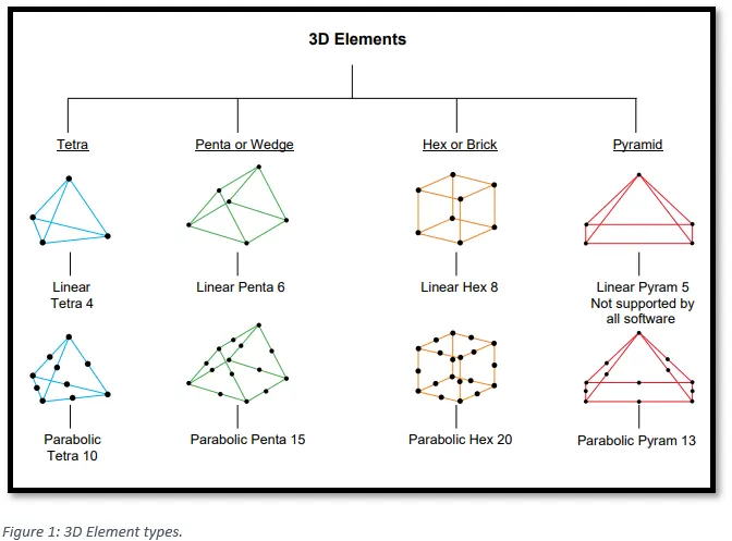
Solid Elements can have anywhere between 4 corner nodes (for Tetrahedral Elements) and 8 corner nodes (for Hexahedral Elements).
Solid Elements are used where all three dimensions of the part are comparable. They are used on most complex parts. Anything that is machined, cast or forged will often be represented by Solid Elements.
On Solid Elements, the nodes support only 3 Degrees of Freedom (DOF).
3D Element Types:
Unstructured and Structured Mesh
In ANSA, there are two modes for the generation of solid elements. The unstructured mesh creation algorithms like tetras and hexa-interior mesh and the structured mesh algorithms like Map, Extrude, Layers, Hexa Block etc. The first requires the definition of a closed Volume entity in advance in which the solid elements will be generated, whereas in the latter the Volume is defined automatically when the elements are created. The Volumes may be bounded by Macro Areas and/or FE-model shell elements.
As per the objective of this assignment, tetra elements should be utilised to mesh the volume, hence unstructured automatic mesh generation method using Tetra FEM algorithm should be used. To generate unstructured automatic mesh in ANSA there are four mesh generation algorithms available. These are: Tetra Rapid, Tetra FEM, Hexa interior and Hexa Poly.
Why to use Tetra FEM algorithm?
The Tetra Rapid algorithm gives tetrahedral mesh (and pyramid elements, if the surface mesh contains quad elements). It is most suited for geometries of thick volumes or large domains with significant variation in length of the surface mesh. Such geometries are mainly found in CFD applications.
The Tetra FEM algorithm is most suited for geometries of thin to moderately thick volumes and nearly uniform surface element length. Such cases are most met in Structural Applications.
Procedure:
1) Importing the CAD model.
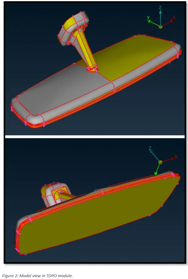
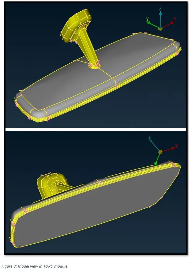
From Figure 2, it can be observed that there are, Single cones (Red Lines) i.e., edges shared with only single surface. OR, the models’ surfaces are not connected. The edges are connected by performing Topo action. As shown in Figure 3.
Additionally, the Rear-view mirror model is made up of four components i.e., Ball Stud, Cap, mirror cover and mirror. As shown in Figure 4.

2) Geometric Clean Up of the CAD Model.
2.1) CONES in the geometry
From figure 3, it can be observed that there are Double cones (Yellow Lines) i.e., edges shared with two surfaces.
2.2) Checking the Geometry.
To identify and isolate on the screen the problematic areas that require the user’s attention, checks manager is used.
In the toolbar on the top of the screen, go to, Checks -> Geometry.
This will open ‘Checks Manager’ window.
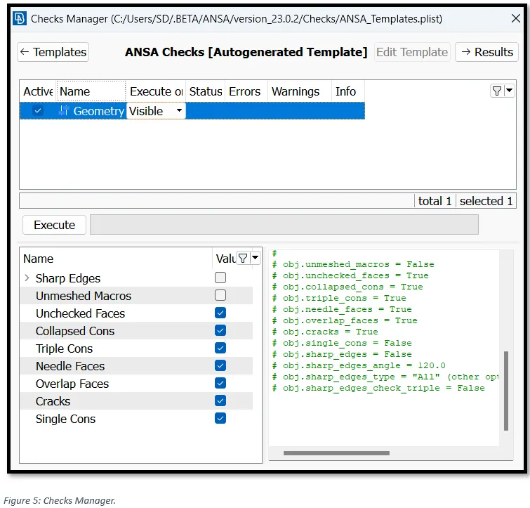
Here we can select the type of problems that may exist in the geometry of the model to be investigated by activating the corresponding flag in the lower part of the window. Keep the default options and click Execute.
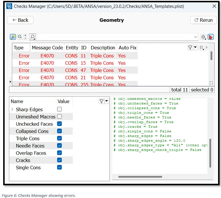
ANSA identifies 11 errors in the geometry of the model. To auto fix the errors select all the errors, right click and click on fix. This will resolve some or all of the errors.
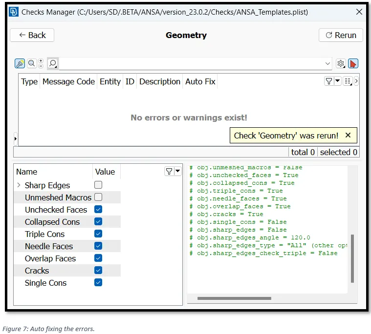
As seen from Figure 7, Geometry is now free from errors.
3) Setting up Quality Criterion.
In order to avoid deviation from the quality after meshing, we need set up quality ranges. In Utilities tab, select ‘Quality criterion’.
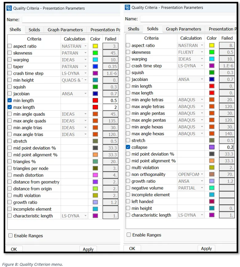
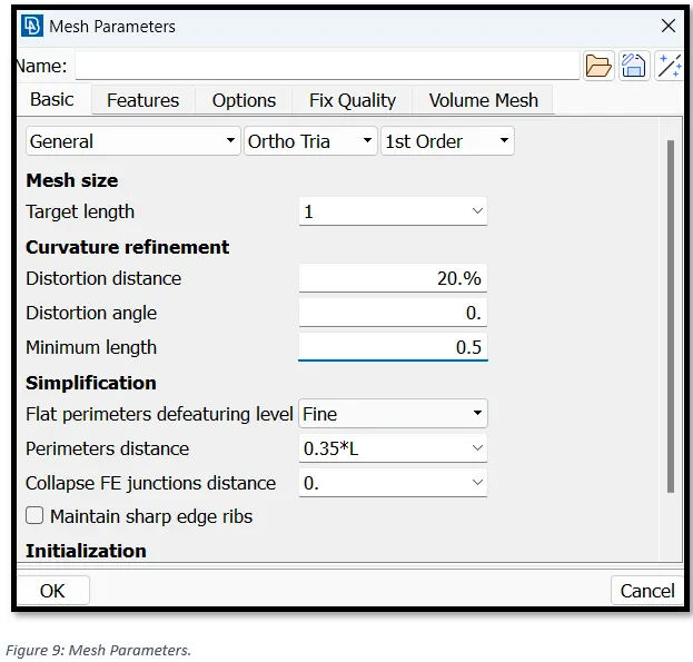
Setting up mesh parameters. In Utilities tab, select ‘Mesh parameters.
4) Assigning mesh element length.
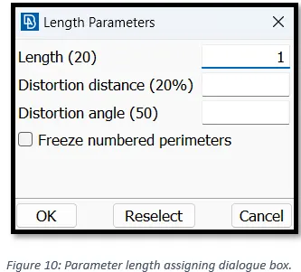
In the Mesh menu, go to, Perimeters -> Length -> Box select the model -> set Perimeter length as 1.
5) Meshing.
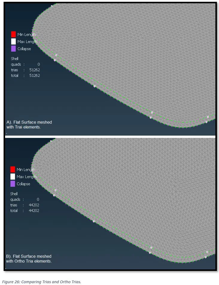
The curved features in the model will be captured using “ortho tria” elements, since surface quality of the mesh is better in case of “ortho tria” when compared with normal tria elements.
Since, the computational time for ortho tria is more than normal tria, we would mesh the flat surface with normal tria elements.
5.1) Meshing of Ball stud:
To mesh the Model area by area, switch to the mesh module, then go to, Mesh Generation -> Best. In the ‘Feature section, select “Macro Area”. Now one by one click on the areas to mesh.
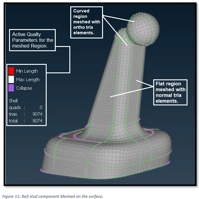
The quality of the volume mesh depends highly on the quality of the surface mesh used for its generation. It is important therefore to ensure that the surface mesh is of good quality, by performing Quality checks and improving the surface mesh before the volume mesh generation.
To generate tetra elements inside the enclosed surface mesh volume, switch to “volume mesh” module.
For generating the solid mesh using unstructured mesh creation algorithm, ANSA requires the definition of a closed Volume entity in advance in which the solid elements will be generated.
The Volumes may be bounded by Macro Areas and/or FE-model shell elements.
For the definition of simple closed Volumes, the Volumes -> Define [Detect on selected] function of the MESH menu is used.
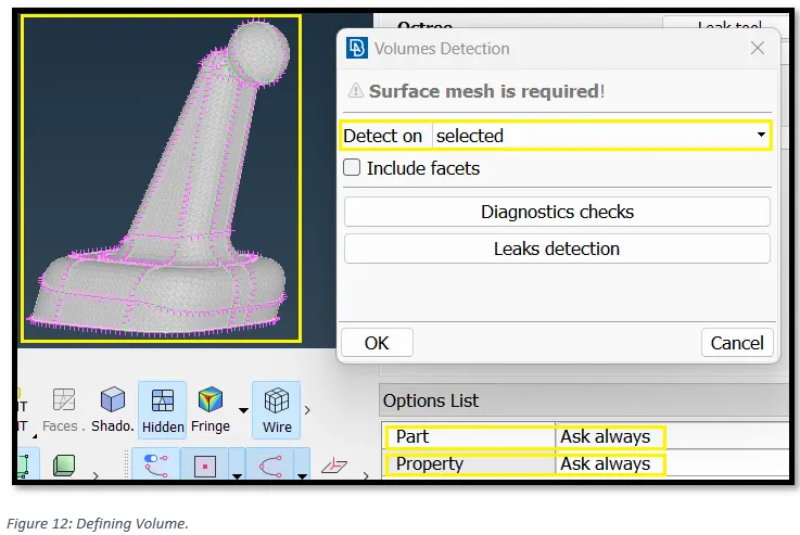
Select the FE-model shell elements, in the option list for part and property selection, select on “Always ask”. Then press ok.
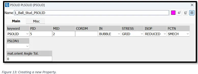
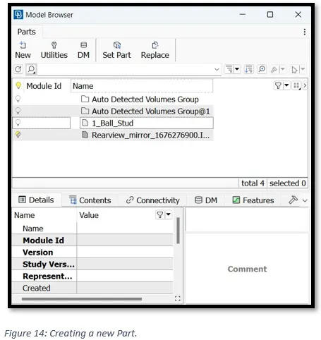
This will prompt us to create a new property card and a new part. Create the new property and a new part as shown in the figure below.
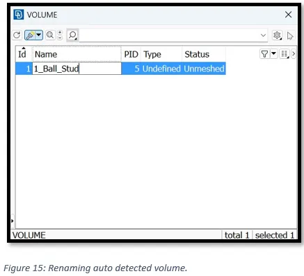
Now, renaming the auto detected volume for easy identification (Figure 15).
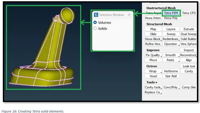
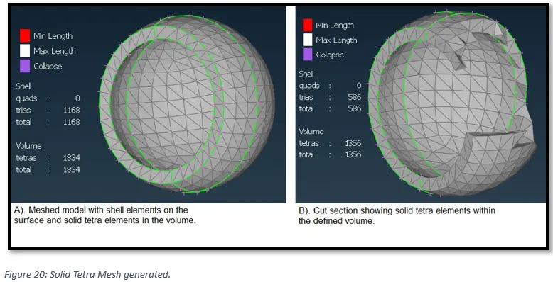
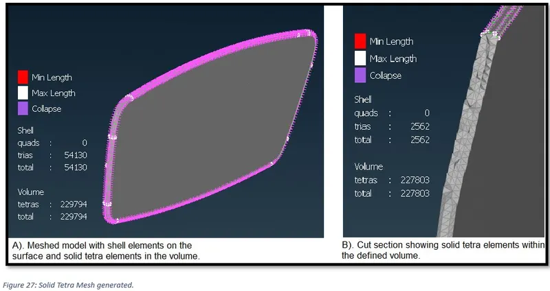
After defining the volume, to create tetra solid mesh go to, Unstructured mesh -> Tetra FEM in the volume mesh module (see Figure 16). Then select the volume and middle click to accept.
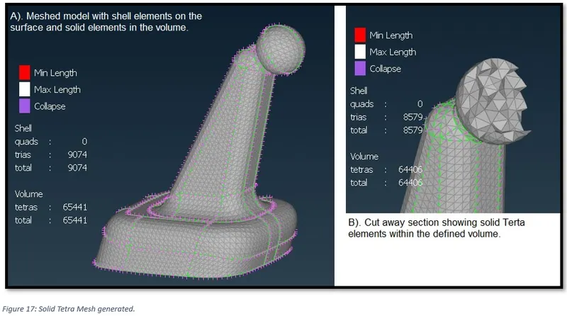
Finally, Figure 17 shown Solid tetra mesh with no failed elements.
Following rules for should be kept in mind to obtain a good mesh:
- Features should be captured properly.
- Proper Mesh Flow.
- Check if there is any dysconnectivity in the mesh.
- Quality Criteria should be satisfied.
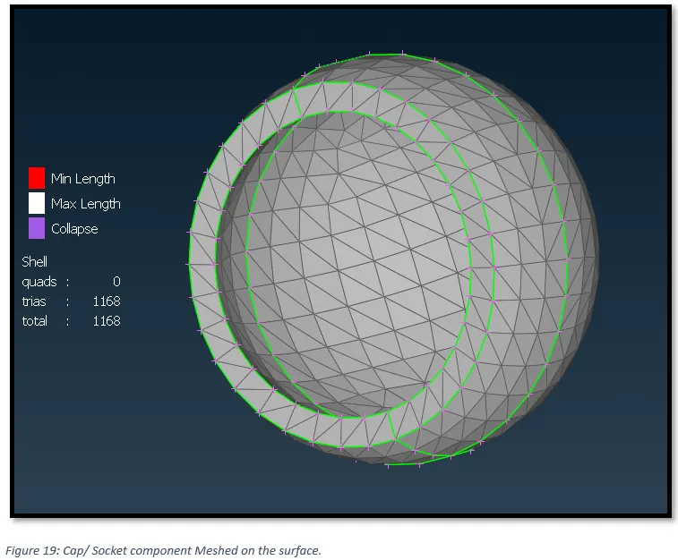
5.2) Meshing of Cap/ Socket.
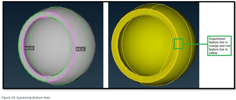
As seen in figure 18, some feature lines are very close to each other so, the feature lines are supressed to avoid element failure and a new feature line in the middle is created to capture the surface feature. Middle feature line can be created by projecting the mid curve on the surface.
5.3) Meshing of Mirror Cover.
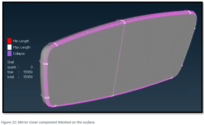
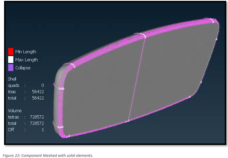
From Figure 22, It can be seen that one solid element is failing for the quality criterion (Tet Collapse).
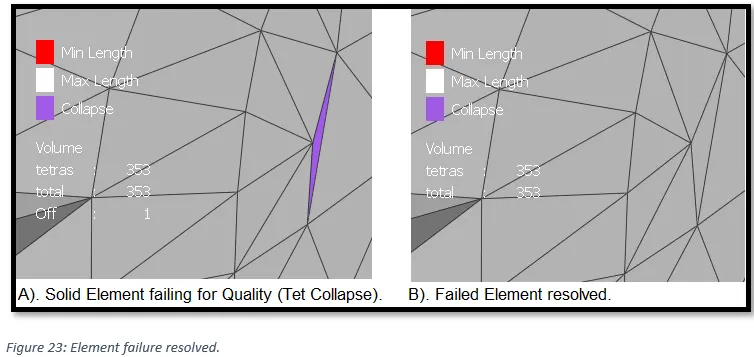
To fix the quality issue go to, Improve -> Fix Quality. Make sure that the solid elements do not have any raised edges or kinks (depression on the surface) after fixing the quality issue.
Note: It might happen that upon fixing the quality for solid elements the shell elements on the surface might fail. That means the quality of the volume mesh depends highly on the quality of the surface mesh used for its generation. It is important therefore to ensure that the surface mesh is of good quality, by performing Quality checks and improving the surface mesh before the volume mesh generation.
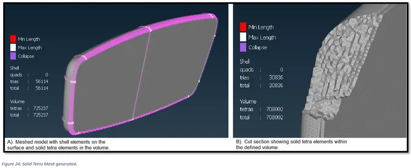
5.4) Meshing of Mirror.
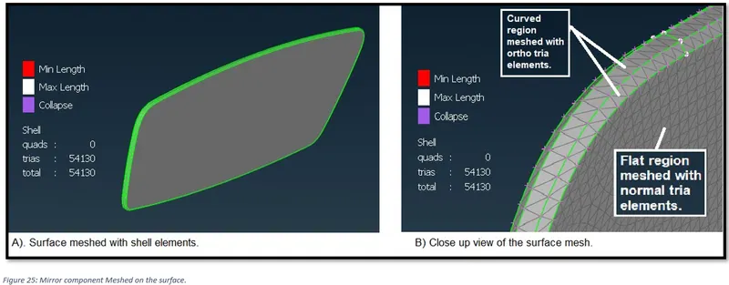
On comparing Tria mesh and Orth mesh on a flat surface (Figure 26), we can observe that the Otho tria mesh has created a smaller number of elements as compared to normal tria mesh, this means less computational time during simulation. But, the tria mesh have created more uniform patten as compared to ortho tria mesh, and since an improved mesh is a prerequisite for good volume mesh generation (as there will be no quality issues like Tet collapse) hence tria mesh is used for meshing the flat surface,
5.5) Final meshed model.
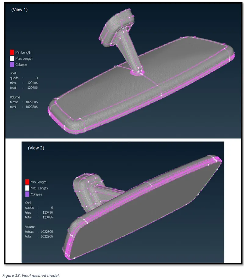
Figure 28 shows the entire model with surface and volume/ solid mesh. There are no failed elements and the total number of elements for shell and volume mesh are shown in the figure.
References:
ANSA_User_Guide