Week 6 - Creating connection for Rear door
Connection in ANSA
Aim: For the given Rear door FE model, creating and apply different PIDs for different components. And performing suitable connections to it.
Model:
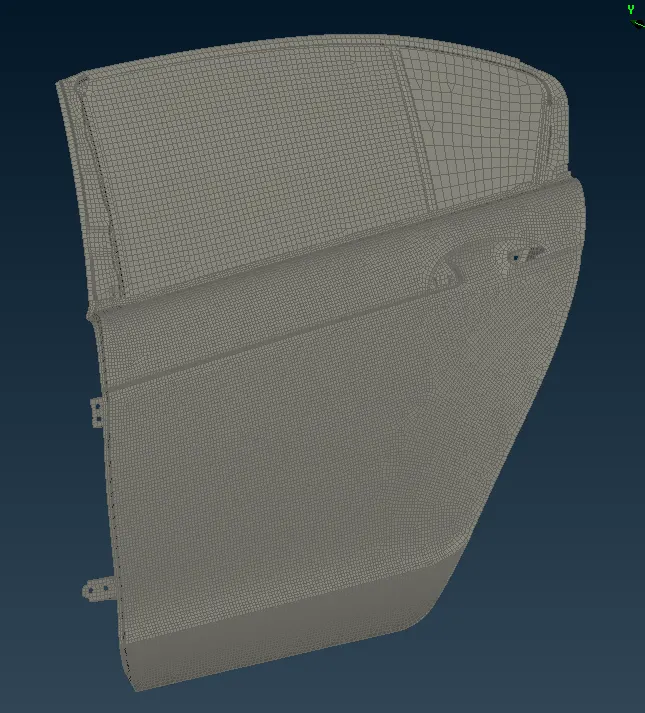
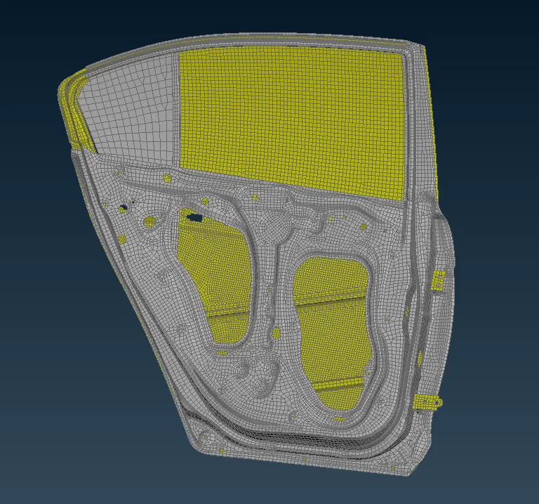
Side Door Model of Car
Introduction:
1D Elements: 1D elements are simple connection between the nodes
Standard 1D elements are
RBE2(Rigid link to distribute load having infinite stiffness)
RBE3(Rigid link to distribute loads)
Beam/Bar (Non rigid link that has a property that include a cross-section and material definition)
Connectors:
Connectors are the geometric entity that define the connection between other entities, in simple word we can say that connectors are used to connect the un- connected parts of the model, so that load can be transfer from one part to other parts.
Used for welding, bolts, adhesives etc
Link geometry of FE entity
Can be realized into FE representation of welds, bolts etc.
Connectors allow for easy and rapid creation of FE welds, bolts, adhesive etc.
Types of Connectors:
Spot: Connection at a point, spot weld rivet etc
Bolt: Connection at hole location
Trim Mass: Non-physical mass, simplification through the replacement of parts with mass only or add mass to existing part
Seam: connection along length, seam welds, connect geometry only
Area: Connection of areas, example Adhesives
Etc….
Connectors: Terminology
Link Entities:
The entities that are being connected
User can explicitly define links entities or specify a search tolerance
Can be components, elements, surfaces, nodes, or tags
Typically, components are linked
Connector location:
Where the entities are linked
Nodes: created at the node location
Points: created at the point location
Lines: created for the lines
Elements: created at the element location (adhesive only)
Surface: created at the surface location (adhesive only)
Connector State:
Whether an FE representation of connector has been created
Unrealized: The initial status of the connector entity upon creation, it means connector is created but not realized.
Realized: The status only if creation of FE weld representation at the connector was successful.
Failed: The status only if the creation of FE representation at the connector was not successful.
Procedure:
- First, we have to define the property for each and every component, because the different component will have different thickness and made up of different materials, so we have to define the property for each and every component of the side door of the car.
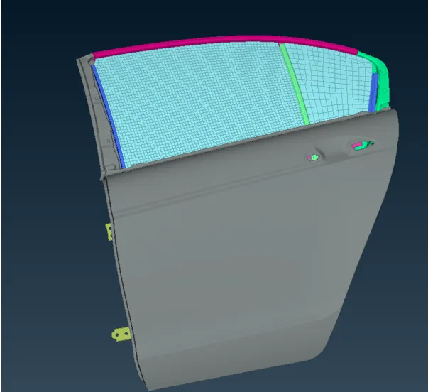
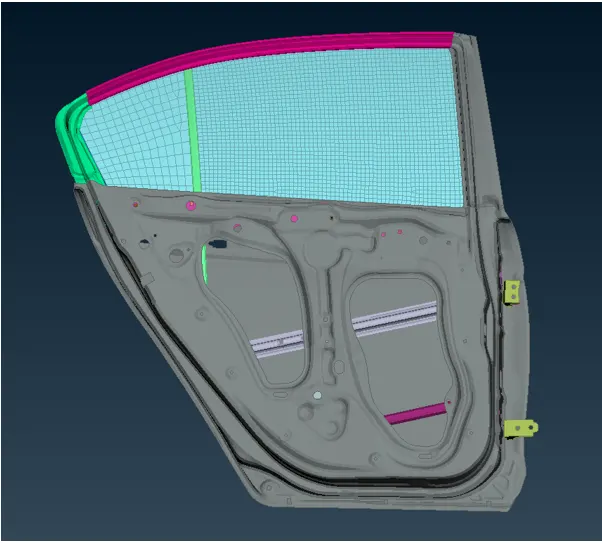
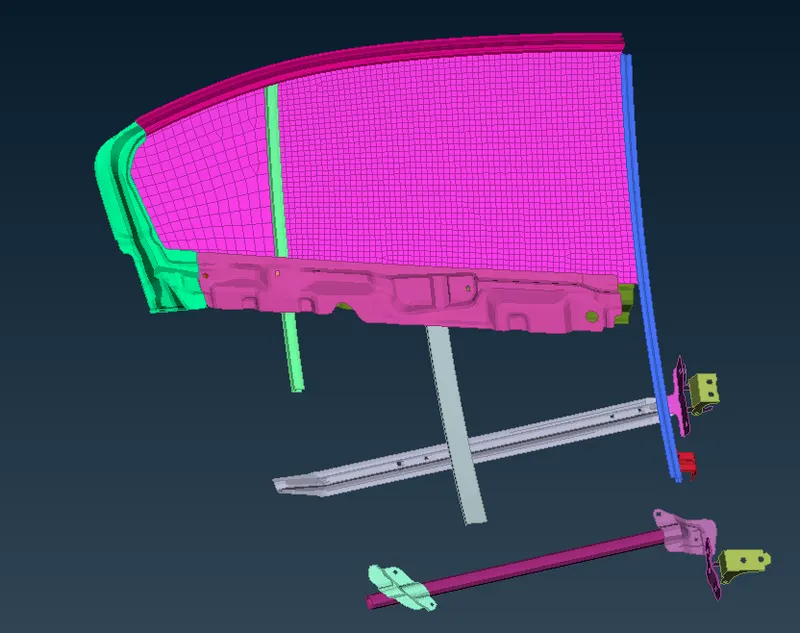
Different Property is set to the different part of the components
- After deploying all the properties now, we can start doing the connections, firstly we will model the Door Handle, here we don’t have any door handle model, so we can represent it by rigid element
Rigid element connection
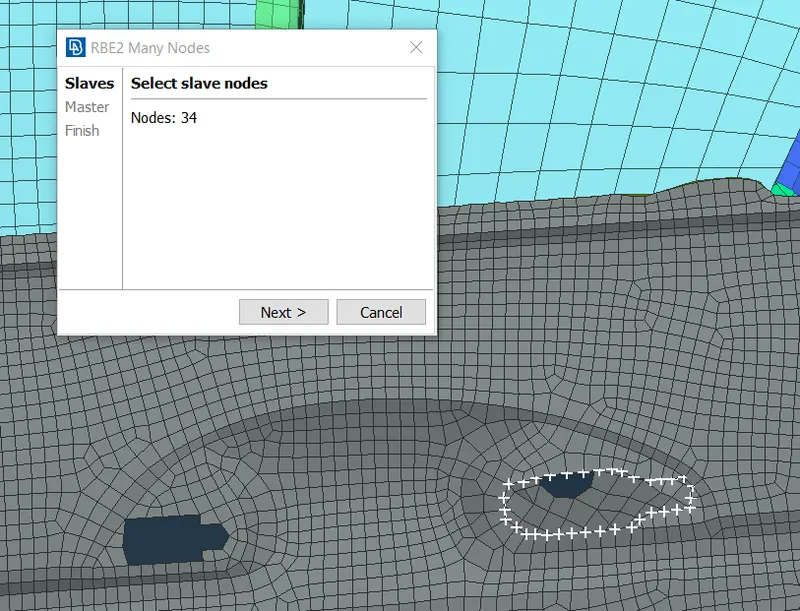
Here we are using many node RBE2 option to make connection, basically connection made from cluster of RBE2 with master node at the centre
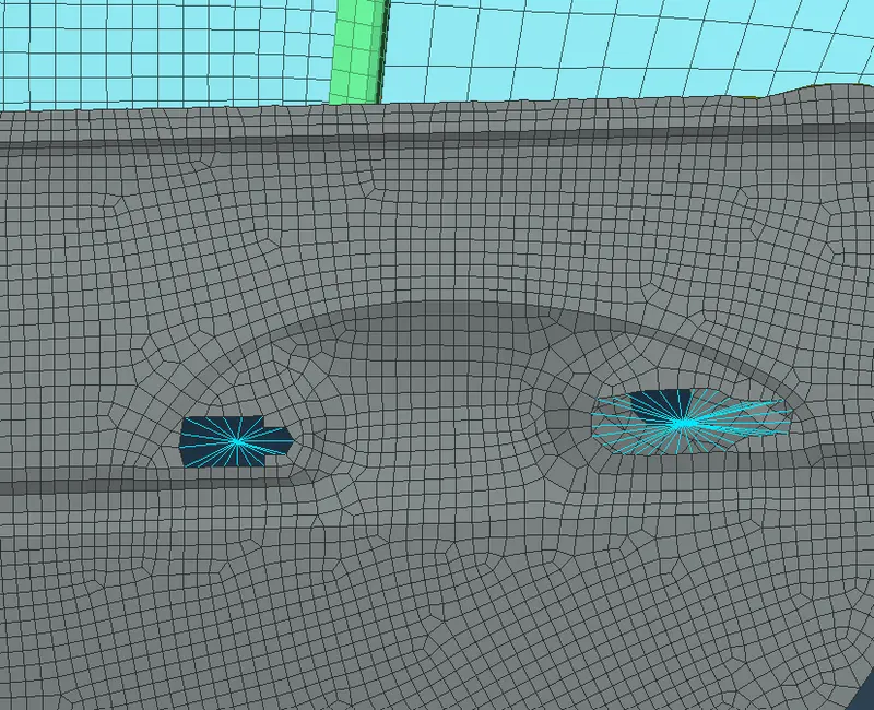
Now we don’t have any door handle model, so we model it in this way and, now we can add a door handle mass at the connection between these two connections.
- To create or define a mass, you have to go to CONS-Mass option.
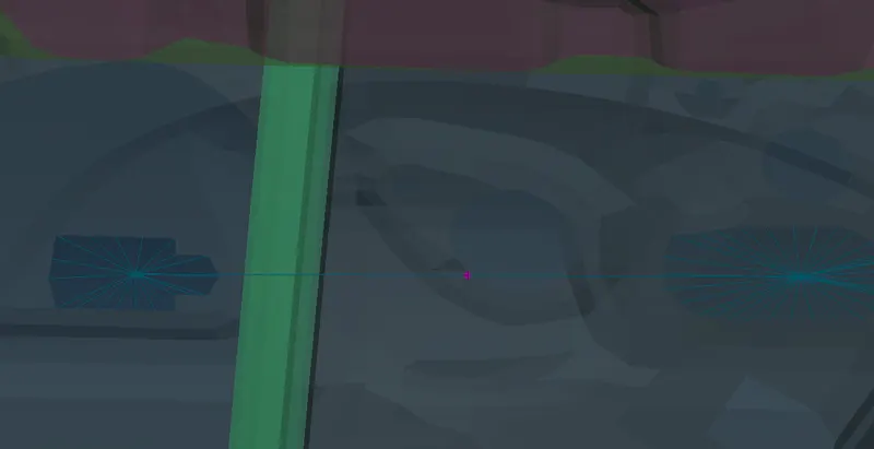
Con-mass is added at the centre of the connection, and this represented a door handle for your car
- Now we connect the hinges by using cluster RBE2 element along with 2 node RBE2, as it is a hinge point then it is rotated about particular axis, for opening and closing of the door
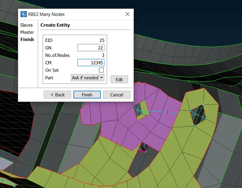
Here we only free the rotation about z-axis
BOLT connection
Connection establishment of two hole by using BOLT connection
- Now for Bolt connection, we basically use two methods to create bolt connection, one is manual method and other is automatic creation of bolt by the help of connection manager.
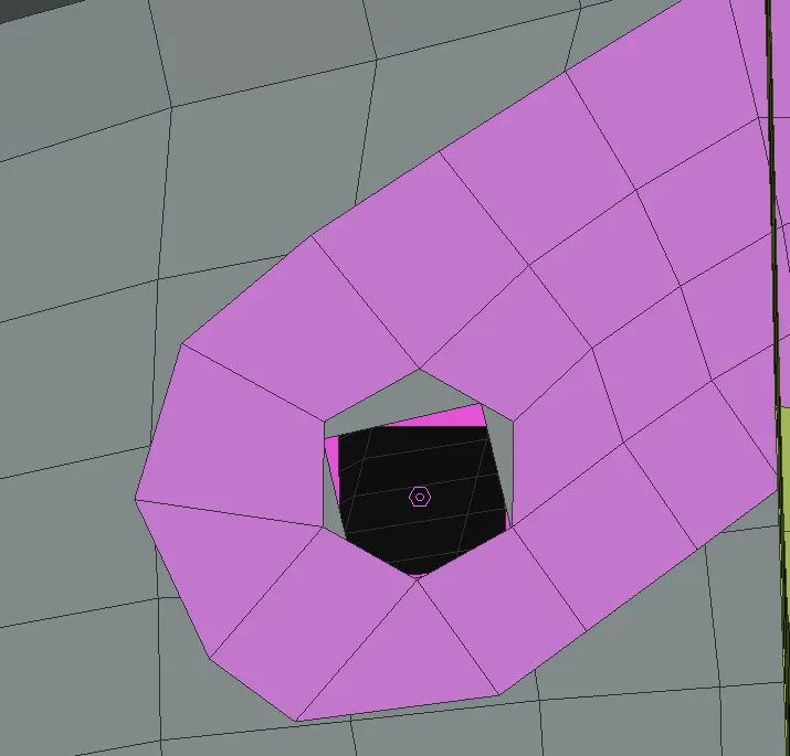
Converting a 3D point into Bolt
- To create Bolt by using connection manger, firstly we have to create the 3D point at the centre of the hole by using On COG option in geometry panel, after creating the 3D point, next step is to convert that 3D point into bolt by using convert option in Assembly section, after converting it to Bolt, we can see the symbol of the bolt, Now to realize the connection we have to go to connection manger option in Assembly section, here we have to define the number of parts to be joined as P1, P2, P3… , also we have to define the Bolt connection as rigid, and then we have to specify the search tolerance and then click on Apply and then click on Realize to realize the connection.
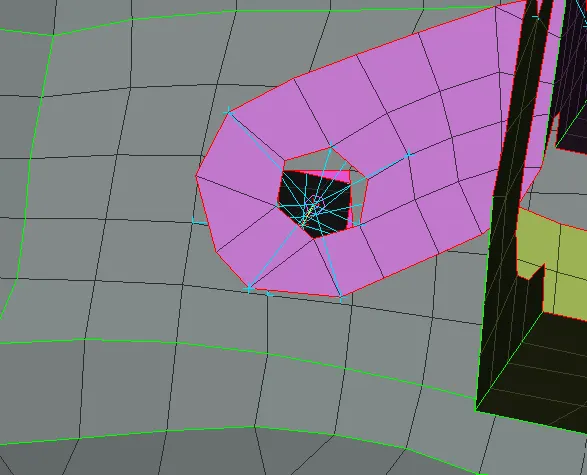
Bolt connection by using Connection Manager
- We can also create Bolt by using cluster RBE2, selecting one hole at a time and join it by cluster RBE2 and to define the bot body or stem we can use 2-Node RBE2 to make connection among the parts.
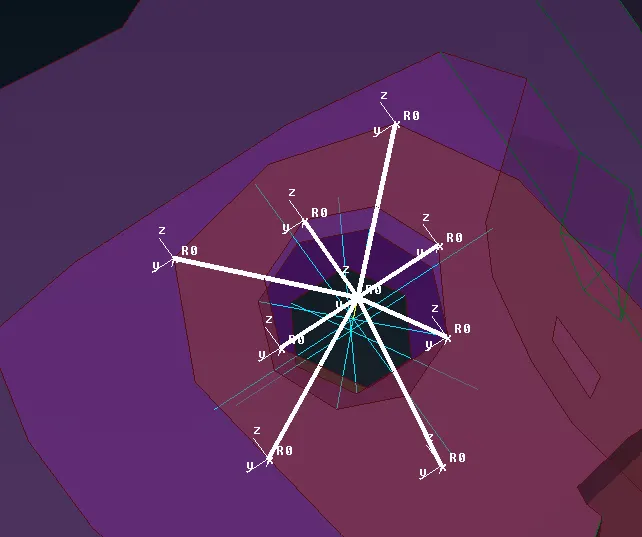
Manually created BOLT connection by using RBE2 elements
SPOT weld connection
- Now we create the Spot weld connection to join the parts, to create spot weld firstly we have to define a 3D point between elements by using ON COG option in geometry Panel, select the Edges and then creating the 3D point between the selected edges, after that we have to convert it into Spot weld by using convert option in Assembly section.
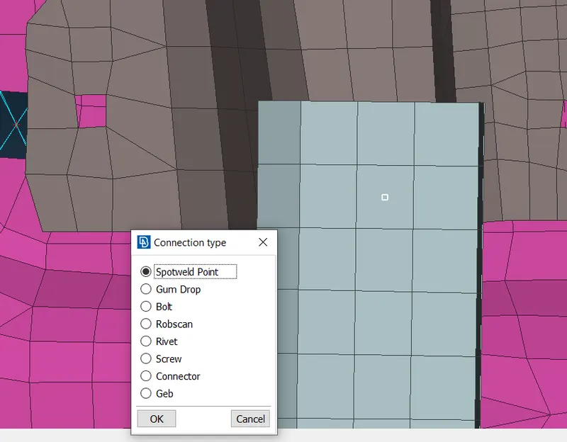
Converting 3D point into Spot weld
- Here we create the spot weld, but our connection is not realize yet, for Realizing the connection we have go to Connection manger in Assembly section, here we have to define the parts that needed to joined as P1,P2 and then we have to define the search tolerance and also we have to define the thicker side of the part to create weld at it, after that we have to define spot connection as RBE3-HEXA-RBE3 and then we have to click on Apply and then click on Realize to make the connection.
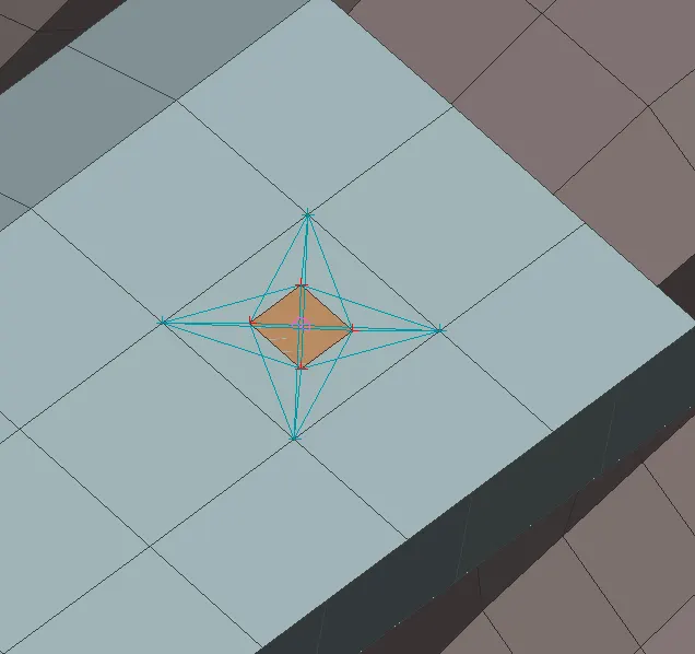
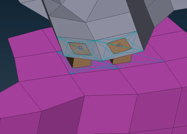
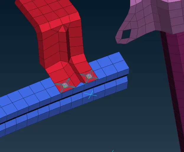
Spot weld creating to join different parts of the side door
SEAM weld connection
Seam weld connection can be represented in two ways
- By Rigid elements
- By Shell elements
Note: Representation of weld connection will vary domain to domain, here we are creating seam weld connection on the basis of NVH domain
To define a seam weld connection firstly we have to define a seam weld line, whenever we have CAD data provided it is called RAW connection data, from which FEA engineer have to derive a data which can be re-enter to the ANSA Database after which connection can be deployed
Preparing the connection data from the raw connection data, firstly we need to find-out the length of the connection, the length of the connection can be taken it as a curve, we can use Con2curve option to create the curve, then we have to convert this curve into actual connection data.
- To create Seam weld connection firstly we have to define the length of the weld connection, for that we have to create a curve from FE by using FE2curve option in perimeter panel
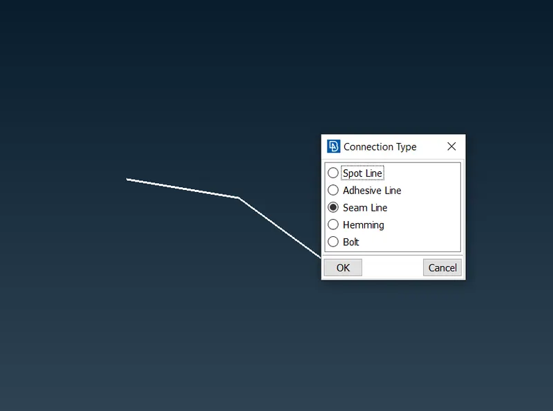
- After defining a curve now we have to convert this curve into Seam line by using convert option, now to realize the connection we have to go to connection manager of ANSA, Here we have to define the parts that needed to be joined as p1 and p2 and then we have to define the base sheet among p1 and p2 which is thicker among themselves and then we have to define tolerance and width, here we define the width of the weld by using angle, now it is overlap joint so we are using Overlap-Shell as our FE representation to create the connection, make sure that we have to create connection as Double-row because it is widely used, after setting all the parameter click on apply and then click on Realize to realize the connection as seam weld (Overlap weld connection)
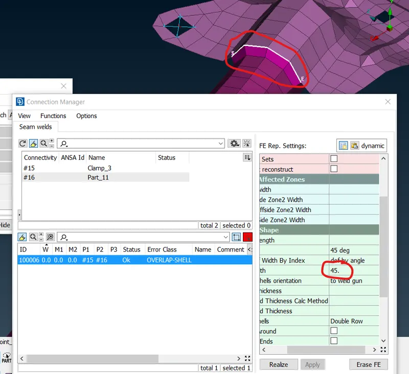
Seam weld Connection
- In similar fashion if we have parts that are perpendicular to each other then we use Y-Joint FE representation to join the parts
Note: Overlap-Shell is a type of FE representation which you should always be using when two parts that are to be weld are parallel to each other. If we have two parts that are perpendicular or normal to each other then the option we are using to deploy the shell connection is called Y-Joint Shell.
Base -Sheet is the area where the weld will be deployed, generally weld base should be stronger than the other part, because if thickness is very weak and when we weld the component, the material deformation will occur at component level and weld will fail.
C-BUSH connection
C-BUSH connection is generally used to connect the door panel with Glass, generally it represents the weather strip of the door that also serve as guide to mirror and support the mirror and also it prevents from the dust entering into the Cabin of the vehicle, also we say that it is a type of seal that doesn’t allow the dust and other things comes under the cabin of the car,
In FE model to connect the glass, as we know glass is very brittle in nature, so we can’t connect it with any rigid elements, we need damping element to create on the both side of the glass, so for connection we using C-BUSH element
C-BUSH is generally a spring element which will having a damping coefficient, it will have stiffness along in all three directions
- To create C-Bush element, firstly we have to create a spot weld line on which we have to deploy a Bush connection, for that firstly we have to create a curve by using FE2curve option.
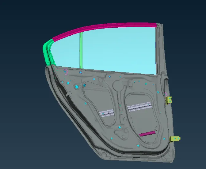
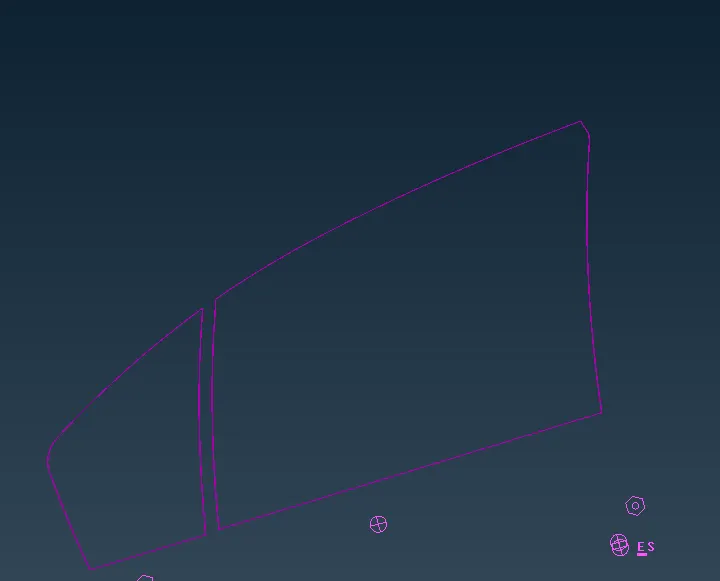
- After creating the curves from the FE, now we have to translate the curve and make a copy of same at distance of 1 unit, after that we have to convert this curve into spot weld by using convert option in Assembly section, while converting the curve into spotweld line, make sure to select each curve one by one, so that it can’t make it as single spotweld curve.
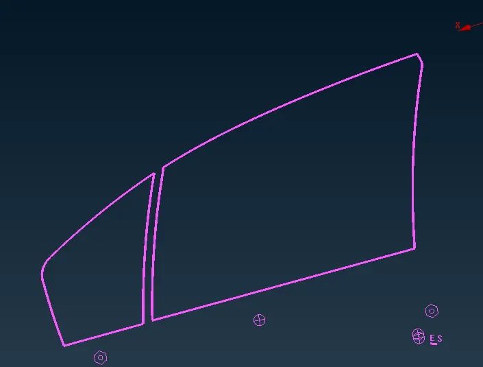
Creating of Spot-weld line from the curve
- For Realizing the C-Bush connection, go to Connection manager, here we have to define the part to be joined as P1 and P2, we are creating two spot lines because one is connected with outer side of the door and other is connected with inner side of the door by using RBE3-BUSH-RBE3, also we need to specify the bush-id which having stiffness value in all 6 direction, then we have to define the search tolerance, also make sure to switch on the option called Keep all branches, because it is best practice that for RBE3 minimum 3 nodes should be created for any connection, after that click on apply and then click on Realize to realize the connection.
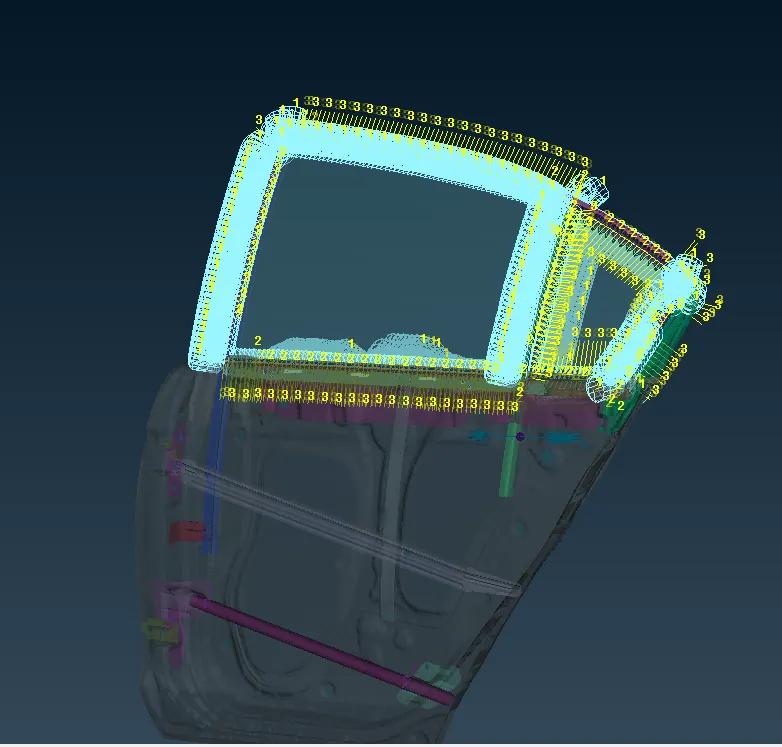
C-BUSH connection around Glass and Body-Panel
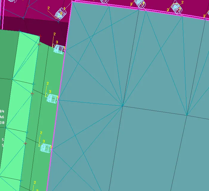
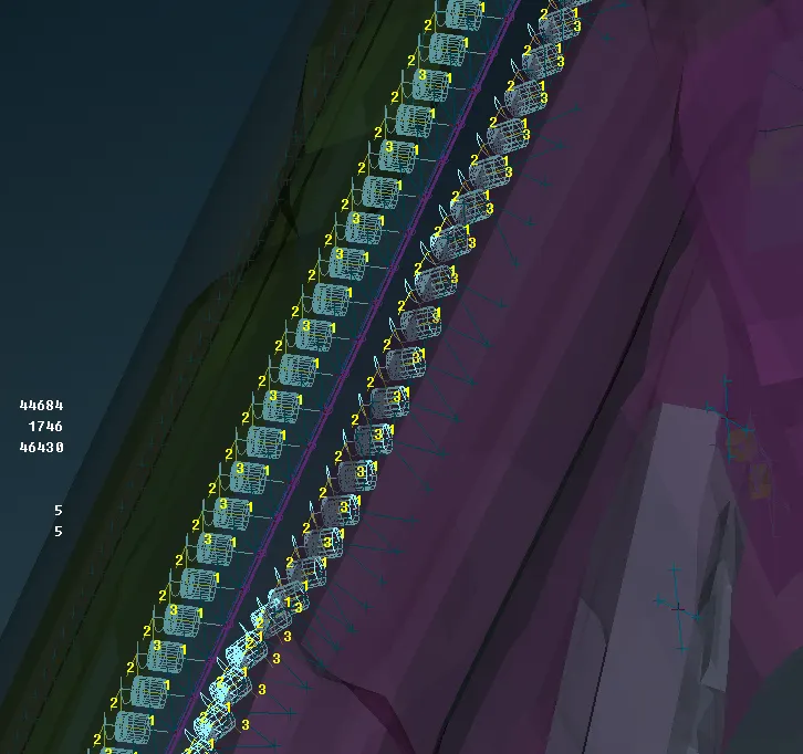
C-Bush connection
- Now each C-BUSH having orientation (local orientation) which is vector based and based upon the direction on which C-BUSH is realized vector coordination will change, but according to new modelling guidelines the orientation should be on the basis of coordinates, which means local coordinate of C-Bush is aligned to the Global coordinate of the vehicle.
- So, we have to convert all C-BUSH coordinates to global coordinates, if we don’t have CID (Coordinate id) and if we give the value 0, by this global coordinate system will align to the element also.
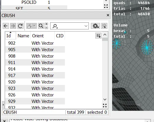
C-Bush with local orientation
- To convert the orientation and setting the value of CID we can use modify command select all the ID and modify it at a single shot
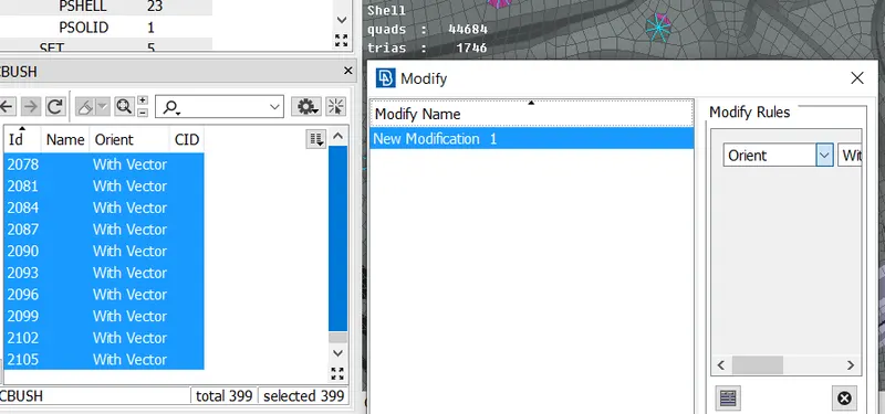
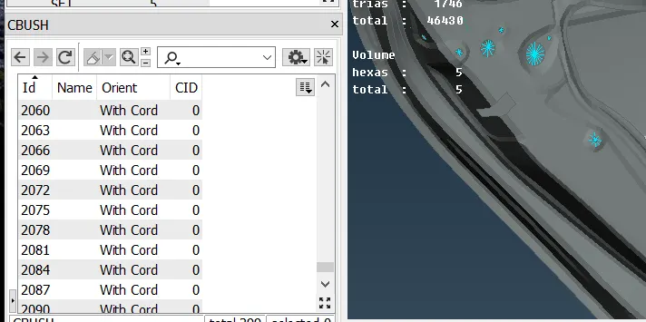
C-BUSH with Global coordinate of the vehicle
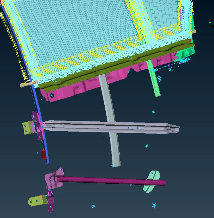
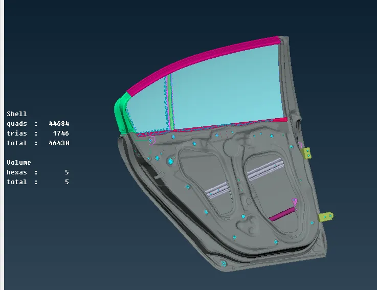
Final connected model
Learning outcomes:
Able to understand the connections for NVH analysis and how to deploy different type of connectors in ANSA