Week 12:Project-1-Meshing of Door Inner Panel Challenge
Week 12 Project
Aim: Meshing the plastic component of the side door of the car, and assigning the thickness to it, and it should follow the given criteria as mentioned below
Target Element Length = 4 Units
|
S.N |
Quality Criteria |
Value |
|
1 |
Aspect Ratio |
5 |
|
2 |
Skewness |
45 |
|
3 |
Warping |
15 |
|
4 |
Taper |
0.5 |
|
5 |
Min. Length |
2 Units |
|
6 |
Max. Length |
6 Units |
|
7 |
Min angle Quad |
45 |
|
8 |
Max angle Quad |
135 |
|
9 |
Min angle Tria |
20 |
|
10 |
Max angle Tria |
120 |
|
10 |
Tria % |
10 |
Instructions to be followed:
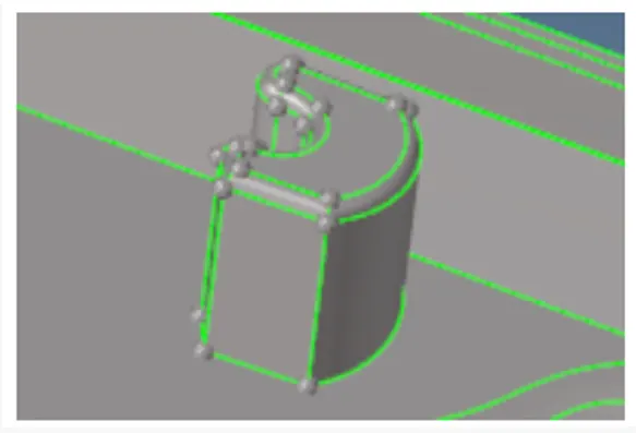
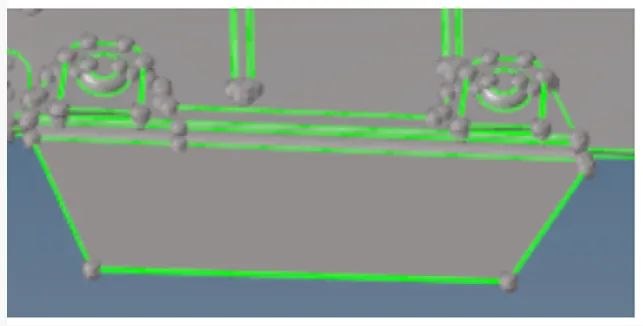
- The area which is having more than 6mm thickness should not model in 2D. You can capture them like in the Below-mentioned picture
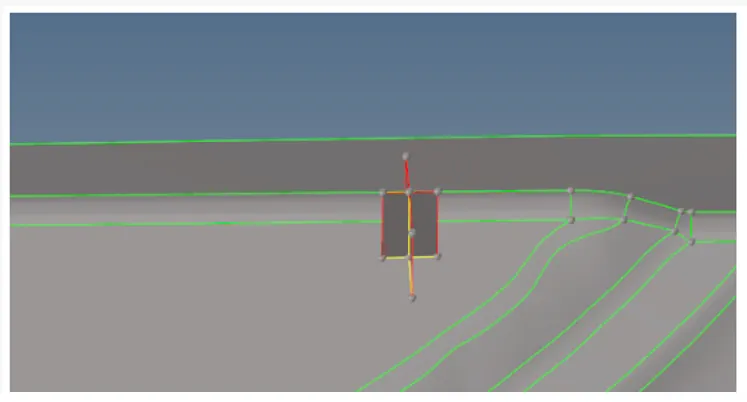
The below image has some geometrical issue on it so modelling them in the 2D will be difficult
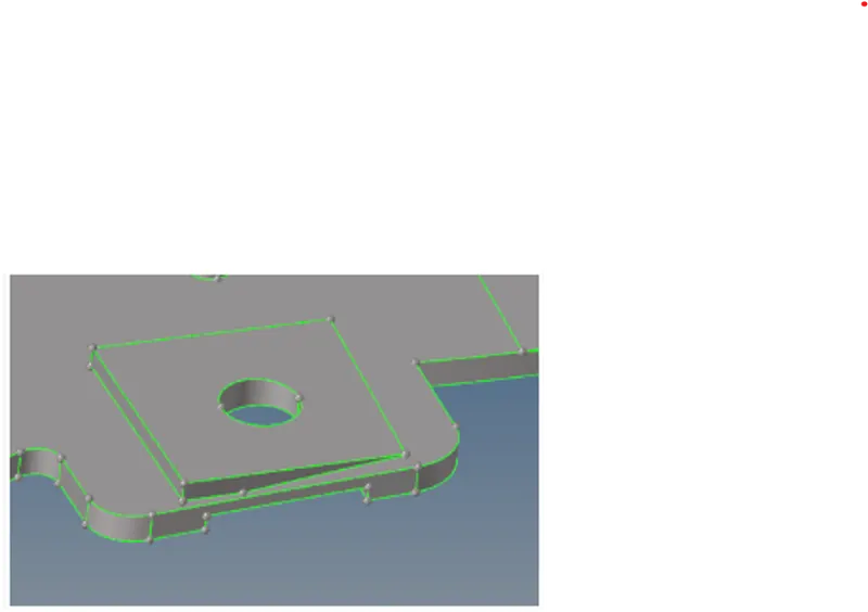
- In those areas, the main objective is to capture the hole so we can take a mid -surface by creating a flat surface with a hole like an image below.
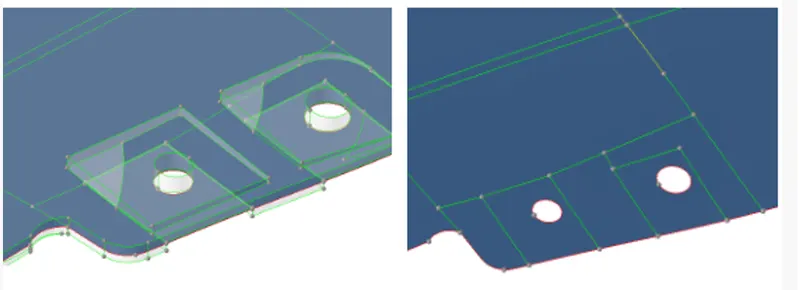
- No need to model the below-mentioned area. The mentioned area does not have a proper attachment to the model.
- For variable thickness areas, Assign the thickness taking an average value of the cross-section
Introduction:
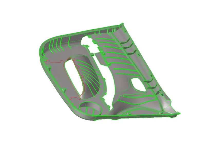
This model is the side door interior plastic component of Automobile. Automakers can use injection-moulded plastic parts in door interior to reduce the weight in the vehicles while meeting side impact protection standards. The door panels cover internal part like the window regulator, the power window motor and the wiring. In older cars, door panel used to be made out of carboard and upholstery within the cabin. On the other hand, most modern car door panels made from plastic. It serves as an interface between the interior of the car and the inner working of the door and between the vehicle occupant and door
They are expected to meet a variety of design specification regarding safety, aesthetics and functionality. In addition to this they are expected to continue the material theme of the dashboard and pillars while concealing intricate electrical and mechanical component for operating locks windows and other features. The door panel has evolved from a two parts system of latch and simple winding mechanism to a more sophisticated enclosure. Doors currently have an inner full width panel consisting of armrests, switches or other control for window and locking mechanism, convenience lights, audio speakers, storage compartment and other features.
Plastic Meshing:
- Plastic meshing is a type of shell meshing where the thickness of the component will vary
- Mid-Surface extraction plays a major role in plastic meshing
- The mid-surface extraction is somewhat tricky when compared to sheet metal meshing
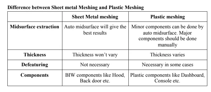
Image source: Skill-lync
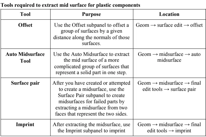
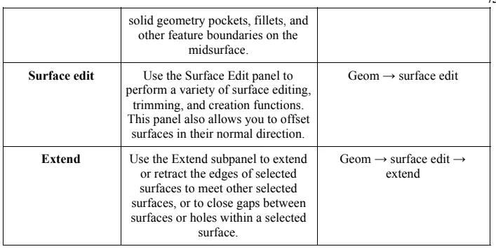
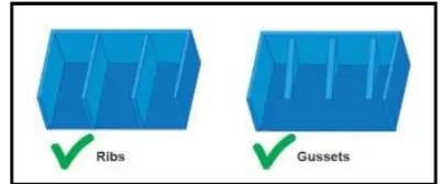
- Ribs are feature in plastic injection moulded parts. They are commonly used to provide additional support and strength to part
We can use the surface pair option to extract the mid-surface of any rib, the extracted mid-surface should be extended to the bottom base mid-surface by using the extend option in surface edit panel
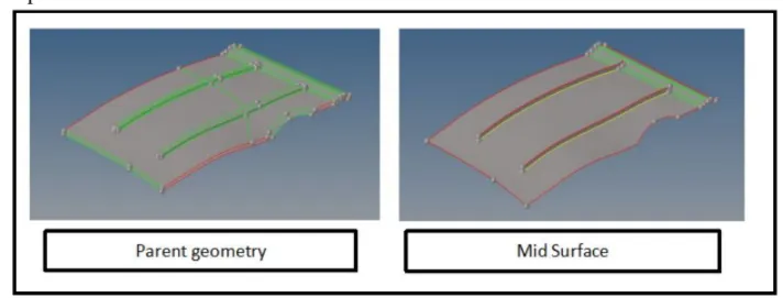
Image Source: Skill-Lync
Best practice to be followed while meshing a plastic component
- Check if the component is symmetric or not
- If it is symmetric, extract the mid-surface only for half portion
- If component is not symmetric, extract the mid-surface for whole component
- We have to check the auto mid-surface for the component, if it is not giving the better result then, we have to jump to other methods
- Split the component into simple parts and try to extract the auto mid-surface
- The distorted surface can be deleted and by using offset and extend command we can stich the surface
- If auto mid-surfacing is not doing well, then we have to do the whole component
- While extracting the whole mid-surface manually we have to be more clear about the base surface, since base surface should not having varying thickness in the most cases
- After creating the base mid-surface, we have to take a look at the ribs attached to mid-surface (we can use surface pair to generate the middle surface and extend the and extend the rib to base mid-surface
- If ribs are within same dimensions, we can use the translate rotate and position option in order to create them again.
- After that the mid-surface of critical parts like dog houses snap fits, mounting clips etc can be extracted by surface pair and offset option.
- Check the rib surface are connected properly to the base. There should be a T-Connection between the base mid-surface and ribs surface
13. Meshing the surface from the complicated region and moving toward free edges
Model:
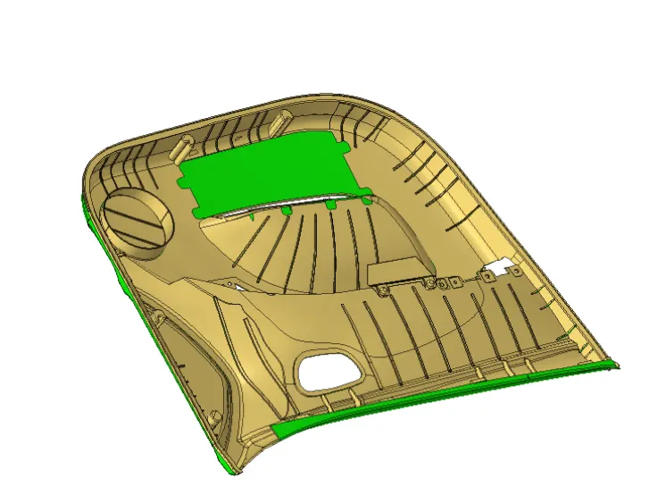
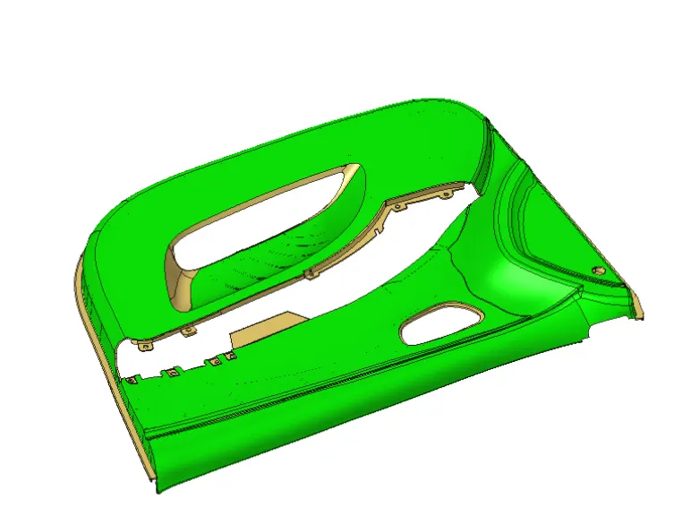
Plastic component with Varying thickness
Note: Here we have Plastic component that having varying thickness, so we don’t use the auto Mid-surface option to extract the mid-surface, here we have to do manual mid-surfacing by offsetting the surface to inner side. Auto mid-surfacing leads to many errors in mid-surface when we have varying thickness component.
Model:
Procedure:
- Import the model from the import option, if we have geometry files make sure to select the particular geometry file format and import them.
- The model is too complex, to avoid complexity we can split the model into different number of parts by using split command, but here we don’t split the model
- Now to create a mid-surface we can use offset option, by offsetting the surface to the middle of the geometry, but before offsetting we have to create a new component on which our mid-surface will lie, also we have another option present in hyper-mesh from which we can offset the surface and creating the mid-surface, for that go to mid-surface option and then go to final edit option to create the mid-surface, This option is very handy when we have very complex geometry, and when we are not capable to offset the surface, Here we have to select the parent surfaces upper and lower surfaces, it automatically created the surface between the two selected surfaces.
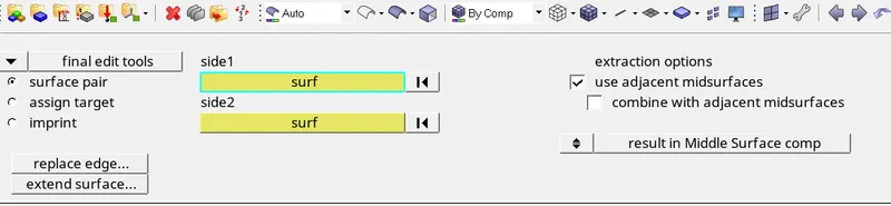
Note: While doing offsetting make sure to check the thickness and also duplicate the surface into the desired component
- But before offsetting the surface we have to clean the geometry manually, so that it doesn’t create any problem during mid-surface
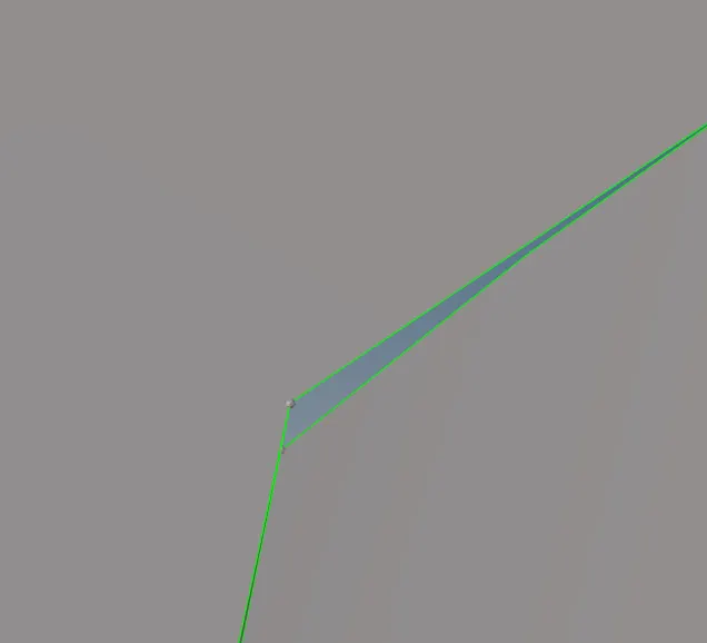
Unconnected surfaces
- Here we lot of ribs that having fillets, so we need to defeature the ribs fillets. To defeaturing go to defeature option > Surface fillet option to defeature the surface fillets
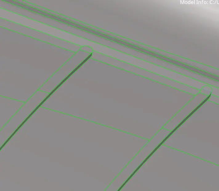
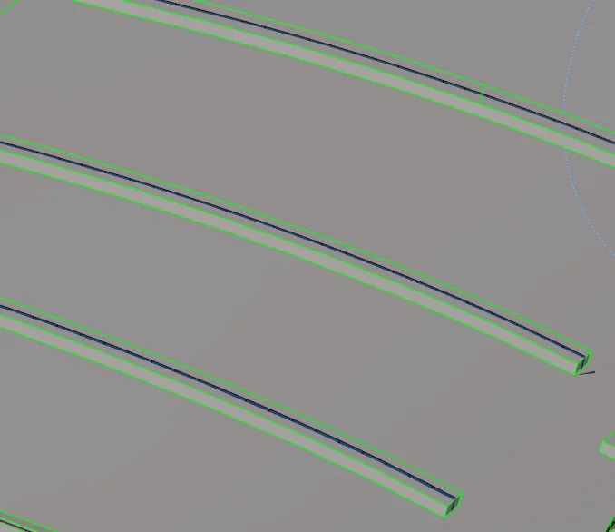
Defeaturing of the ribs
- After defeaturing the ribs and clean the parent geometry, we can now extract the mid-surface from the component by using offset option, also while extracting the mid-surface from offset option can cause some geometrical errors in component, we have to manually check it and clean it.
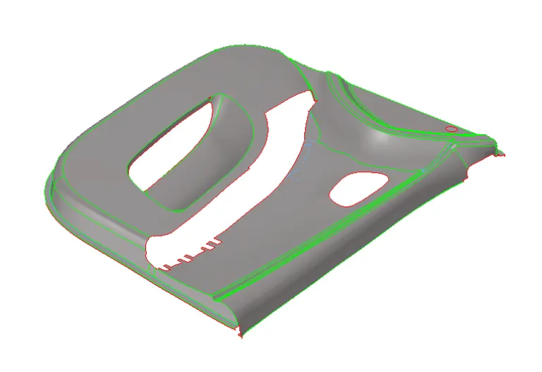
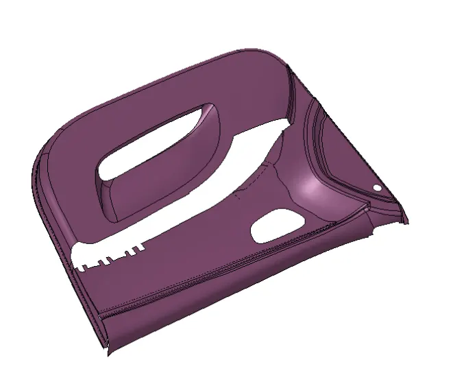
Extracting a mid-surface of Base Surface
- Now we have having different parts that having different thickness, so we have to create mid-surface for each and every part separately, also we can create the new component for that and move them into that component or either we can move them all the middle-surfaces in one component.
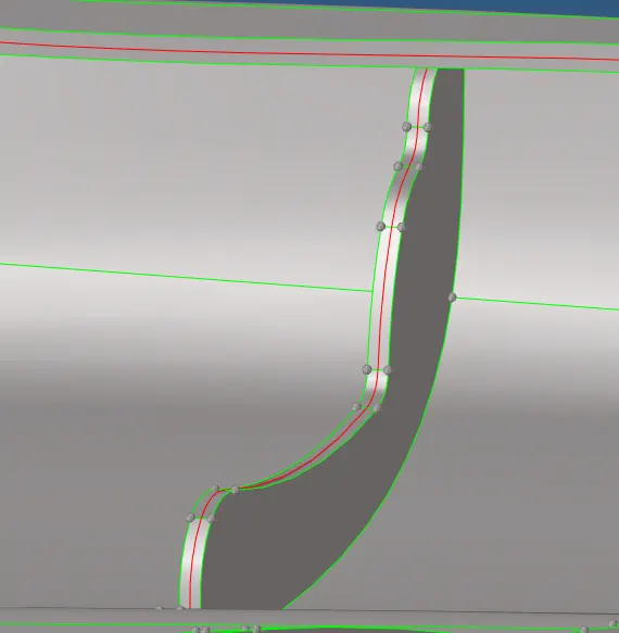
Mid-Surfacing of Ribs
- After creating all the mid-surfaces, we have to attach the ribs with the surface for that we can use the extend command to extend the surface to other surface. For extend command go to Surface edit and go to surface extend option.
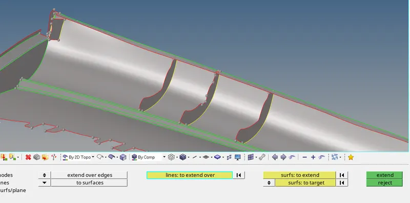
Ribs are attached to the surface
- After that we have to attached all the ribs with the surface by using extend option.
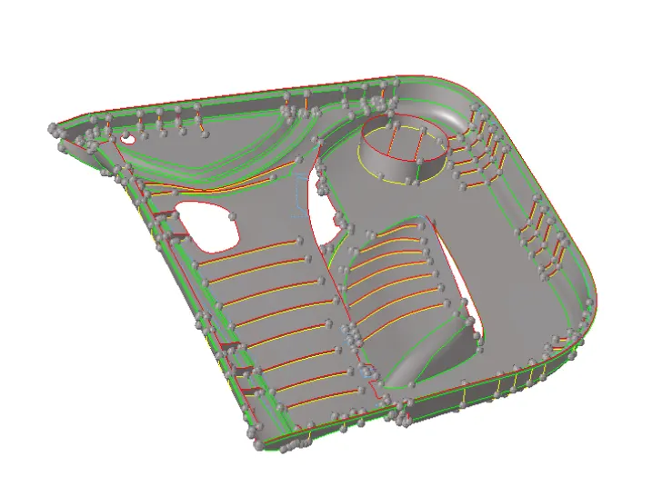
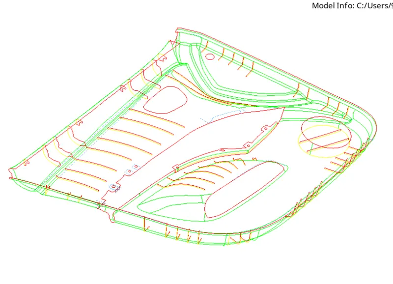
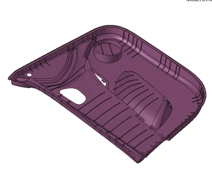
Mid-Surfacing of model
- After creating the mid-surface, we have to mesh the component according to quality parameters as mentioned above
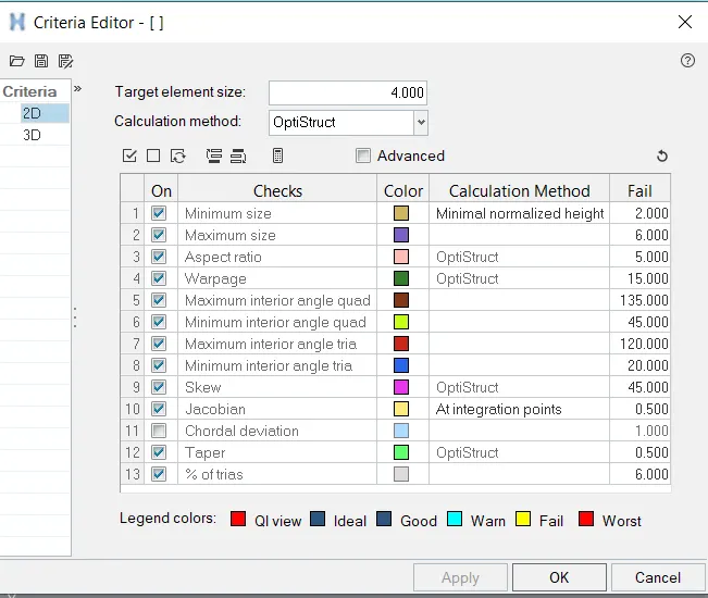
- Here we mesh the small-small part of the component so that we have to get good control over the mesh
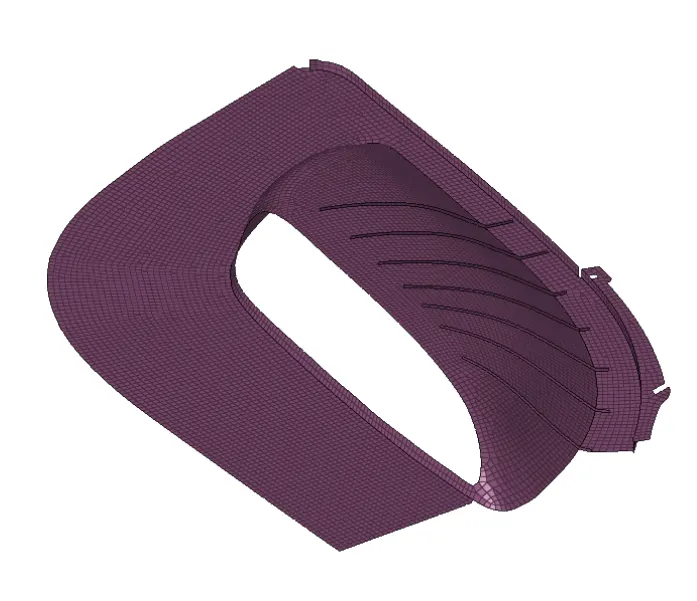
During meshing we have to take care about
- Feature should be capture properly
- No back to back trias
- There should be element connectivity between the elements
- No opposite trias
- No rotational quads
- Quality check to ensure that all element are within good quality
Note: During meshing make sure to check for free edge option at regular interval. It will help us to show that where there is no element connectivity in the mesh
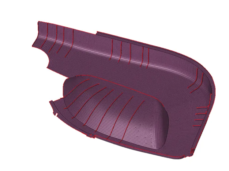
Meshing of Base-Surface with ribs
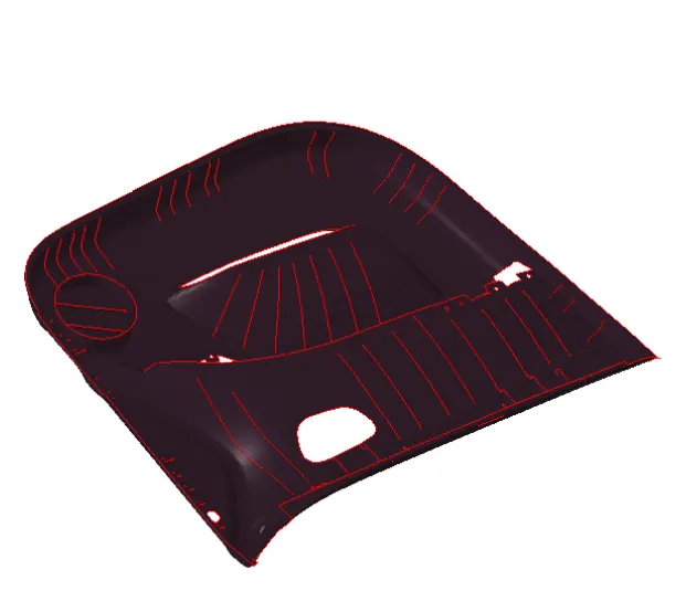
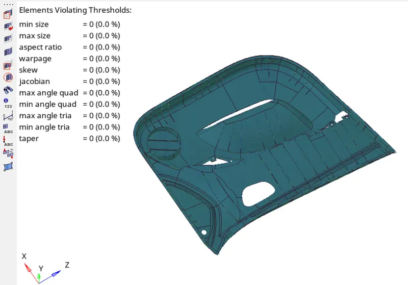
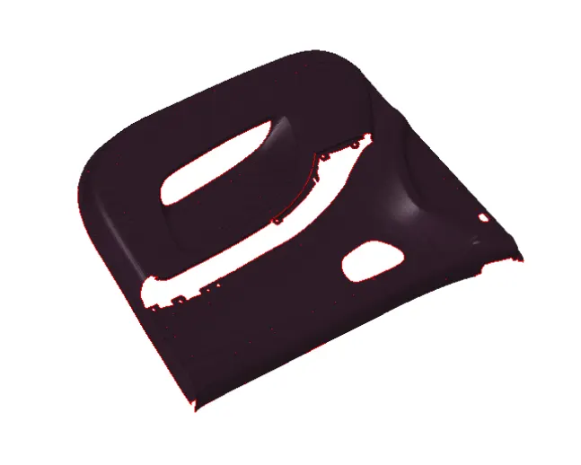
Completely meshed model
- Now next step is to assigning a thickness to the component, but before assigning a thickness to the parts we have to move that part into different component, so that we can apply thickness to every part of the component
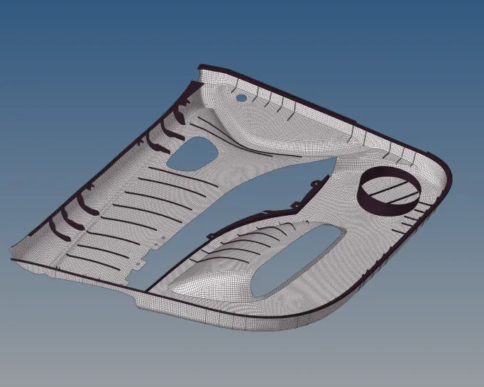
Base Surface is moving into other component
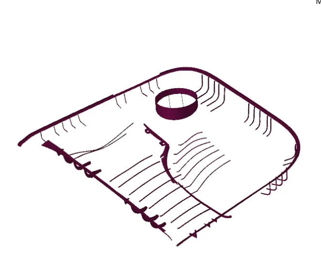
- Here we are left with some parts and ribs that having different thickness
- Now again we have to move that ribs into different component, for that we have to create the component for each and every part which having different thickness
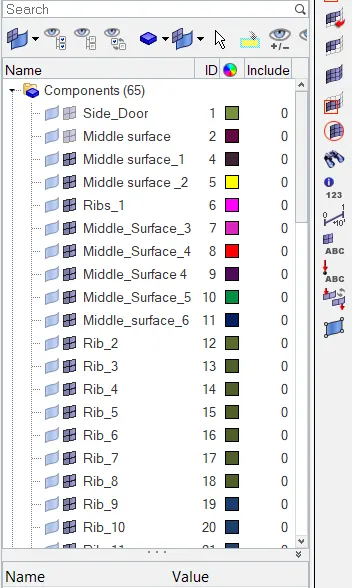
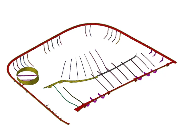
Here we move the ribs and base surface into different component
- Now for assigning a thickness firstly we have to create a property and assign that property to that component, and then defining the thickness to that particular component
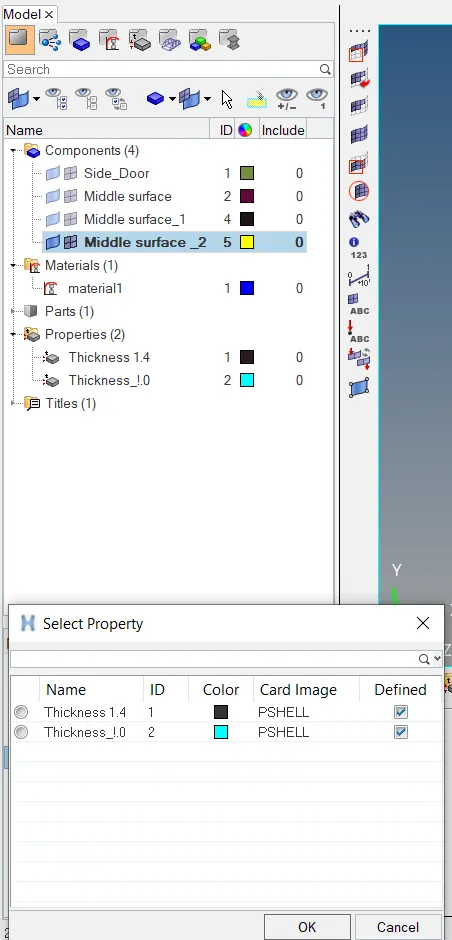
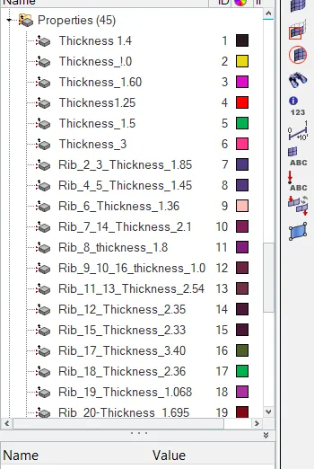
Thickness is assigned to each and every component
- To see whether thickness is assigned to component or not, for that go to 2D detailed representation option in the Tool bar
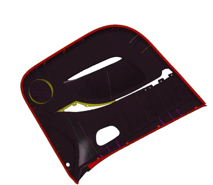
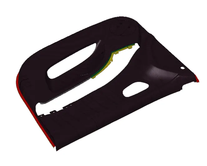
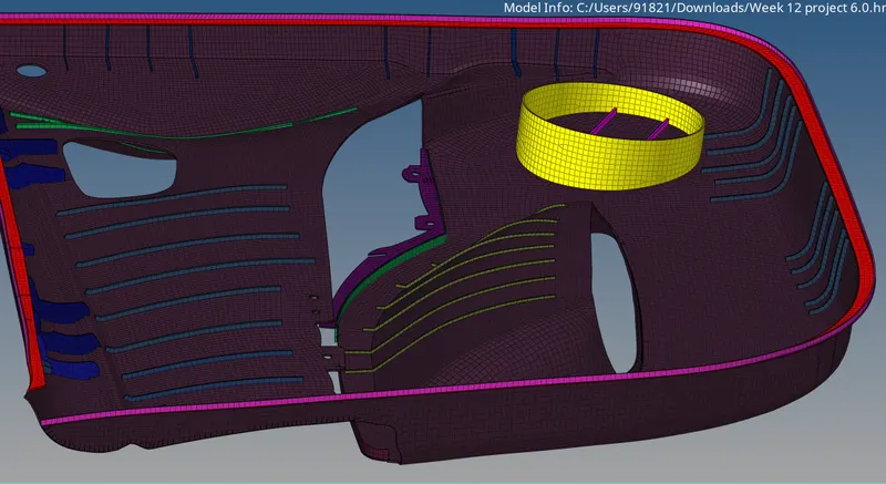
fig: Final Meshed Model
Learning outcomes:
Understanding about the plastic meshing
Understanding about the manual mid-surfacing
Understanding about the methods and techniques to handle the plastic components
Understanding about the difference between sheet metal meshing and plastic meshing