Week 9-Creation of 1D Connectors Challenge
Connectors & Debugging connectors
Aim: Mesh the given model and it should follow the quality parameters, also create the connector to attach the various part of the model.
Target Element size - 5 Units
|
S.N |
Quality Criteria |
Value |
|
1 |
Aspect Ratio |
5 |
|
2 |
Skewness |
45 |
|
3 |
Warping |
15 |
|
4 |
Taper |
0.5 |
|
5 |
Min. Length |
2Units |
|
6 |
Max. Length |
8Units |
|
7 |
Min angle Quad |
45 |
|
8 |
Max angle Quad |
135 |
|
9 |
Min angle Tria |
30 |
|
10 |
Max angle Tria |
110 |
|
10 |
Tria % |
15 |
Model:
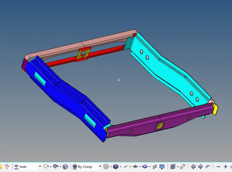
The specific connectors that we have to attach the various parts of the given model
- Right_Rail_2 & Front_truss_1:- Seam-Quad(angled+capped+L)
- Left_Rail_2 & Front_truss_1:- Quad elements
- Front_truss_2, Front_truss_1 & Right_Rail_1:- Spot weldwith 3 Layers and 5 mm Diameter
- Front_truss_2, Front_truss_1 & Left_Rail_1:- Hex (Adhesive)
- Rear_truss_2 & Right_Rail_2:- Bolt Connector
- Rear_truss_2 & Left_Rail_2:- Bolt Connector
- Right_Rail_1 & Right_Rail_2:- Spot-weld with Rigid Elements
- Left_Rail_1 & Left_Rail_2:- Spot-weld withSpring Elements
- Rest all the component left Join them with suitable connectors
Introduction:
1D Elements: 1D elements are simple connection between the nodes
Standard 1D elements are
RBE2(Rigid link to distribute load having infinite stiffness)
RBE3(Rigid link to distribute loads)
Beam/Bar (Non rigid link that has a property that include a cross-section and material definition)
Connectors:
Connectors are the geometric entity that define the connection between other entities, in simple word we can say that connectors are used to connect the un- connected parts of the model, so that load can be transfer from one parts to other parts.
Used for welding, bolts, adhesives etc
Link geometry of FE entity
Can be realized into FE representation of welds, bolts etc.
Connectors allow for easy and rapid creation of FE welds, bolts, adhesive etc.
Although it is very simple to create the weld connectors in hyper-mesh. But, for large model it will take tremendous amount of time, in this case the CAD modeller usually provide an xml file which contain all the location, where we have to make the joint.
Connector file includes XML file and MCF (master connectors file)
If we have connector file, we can directly import it into hyper-mesh
Go to File > Import > Connectors to import the connector files
Types of Connectors:
Spot: Connection at a point, spot weld rivet etc
Bolt: Connection at hole location
Trim Mass: Non physical mass, simplification through the replacement of parts with mass only or add mass to existing part
Seam: connection along length, seam welds, connect geometry only
Area: Connection of areas, example Adhesives
Connectors: Terminology
Link Entities:
The entities that are being connected
User can explicitly define links entities or specify a search tolerance
Can be components, elements, surfaces, nodes, or tags
Typically, components are linked
Connector location:
Where the entities are linked
Nodes: created at the node location
Points: created at the point location
Lines: created for the lines
Elements: created at the element location (adhesive only)
Surface: created at the surface location (adhesive only)
Connector Realization:
The creation of finite element representation of that connector
Rigids, springs, etc. or custom configuration such as ACMs, CWELDS etc
Connector State:
Whether an FE representation of connector has been created
Unrealized: The initial status of the connector entity upon creation, it means connector is created but not realized (connectors are in yellow/orange colour)
Realized: The status only if creation of FE weld representation at the connector was successful (connector are shown in green colour)
Failed: The status only if the creation of FE weld representation at the connector was not successful
Number of layers: number of FE weld layers to attempt to generate the connector, 2T, 3T (when we have to join 3 layers with connectors)
Connect when
We specify the information related to link entities is added to the connector
To connect we have to only add link entity information, for this option you must select the connect what entity and number layers to successfully create a connector
Re-Connect rules
Defines method for connector Re-attachment during part replacement
If link entity is deleted the link entity is removed from the connector
BY ID: if a link entity is deleted the connector retain the ID of the link entity
BY name: same as by the id rule except that entity name is retained.
Connector Module
Spot, Bolt, Seam, Area (from this we can create edit and realize the style of connectors)
Apply mass: adds a mass value to the entity (use to represent the mass of the part that are not present in the model)
FE Absorbs: create a new connector from existing elements of recognizable FE representation of welds, bolts, adhesives etc
Add link: Add link entities to the existing connector
Unrealize: Delete FE representation of welds, bolts, adhesives associated with existing connectors.
Compare: check the MCF (Master connector file)
Quality: check for the duplicate connectors, combine connectors, check the quality of realized elements.
Model:
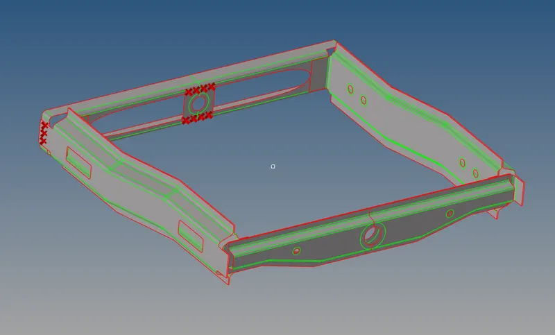
Mid-Surface is already extracted
Procedure:
1. First, we have to check the model to ensure that there is no geometrical error present in the model, so we have to clean the geometry either manually or using the auto clean-up option in geometric panel.
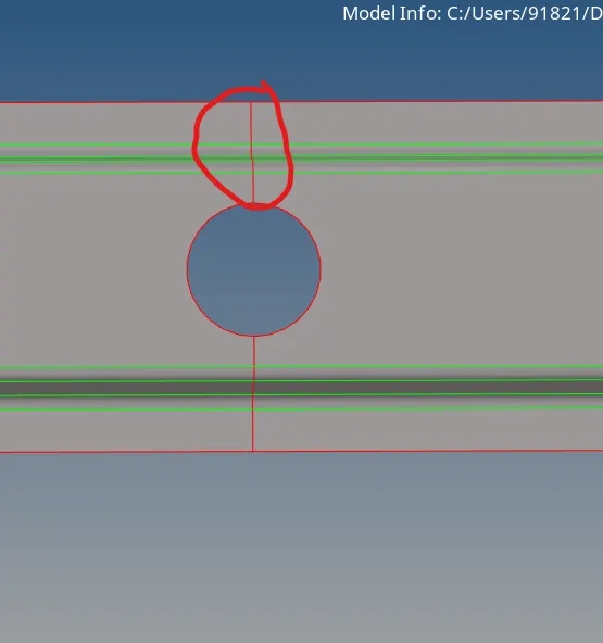
2. Here surfaces are not stich properly to each other, hence it shows us red colour line, so we have to stich the surface by using toggle option in quick edit panel.
3. After completing the geometrical clean-up, we can start the mesh, but before mesh we have to set the quality parameter as mentioned above, for set the quality parameter go to Tool > Check elements > Settings, criteria Editor dialogue box is open
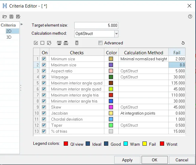
4. After setting the quality criteria or parameter we can start the mesh with Target element size of 5 units
Here we mesh the model in parts so that god quality mesh can be obtain
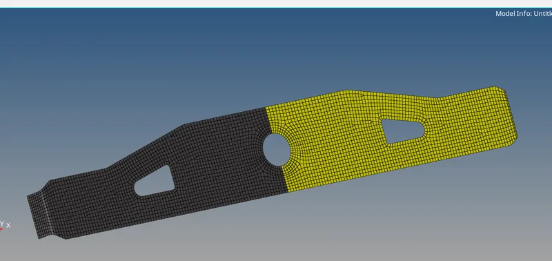
Around the hole we have to create the washer split, for getting proper element near the hole.
5. Step by step we mesh all the part of the model
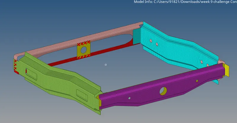
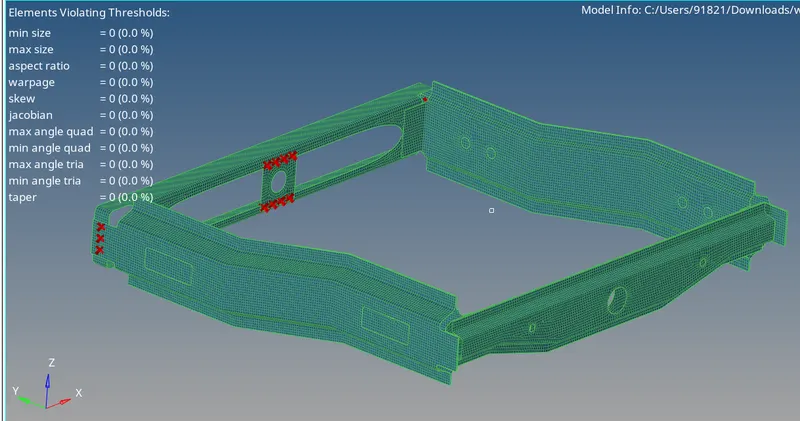
Meshed model
6. Now our model passes all the quality parameters. Now, we have to join this model by the help of connectors. But before creating the connectors we have to define the property and material and also defining a thickness to the model.
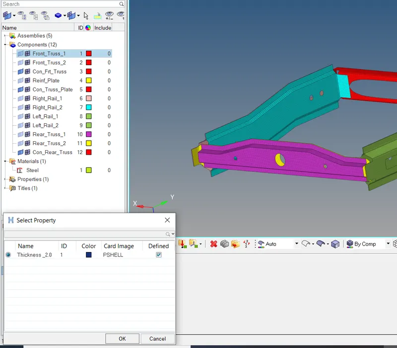
Material: Steel with card image (MAT1)
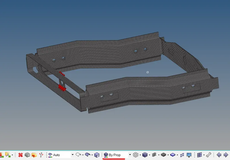
Here property can assign to all the components
- After creating the property and material, we have to assign it to all the components.
Now we can start joining the parts on by one of the given model, by specific connectors as mentioned above
Mainly we have two types of weld connection
- Spot Weld
- Seam weld
1. Right Rail 2 & Front truss 1 (Seam-Quad (Angled + Capped + L)
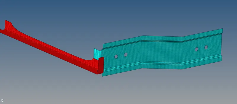
Here we have to join the two components “Right Rail 2” & “Front truss 1” have to join with Seam-Quad (Angled + Capped + L)
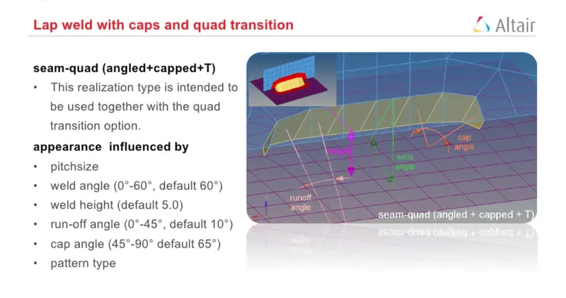
Physical characteristics for seam welding, such as
Weld Angle
Height
Cap Angle
Runoff angle
Source: Altair Engineering
To create the Seam weld, go to 1D panel > Connectors > Seam, in the seam option the type was selected as Seam-Quad (Angled + Capped + L) and we can select the node list or line to specify the seam weld location, we use the node list to specify the weld location, and also set the spacing = 5 ( equal to element size), after that select the component to be weld together, set the search tolerance value to 10 and also specify the weld angle = 45, cap angle = 60 and runoff angle = 10, Now we have to set the property that we created for the weld , hit the button to create the Weld
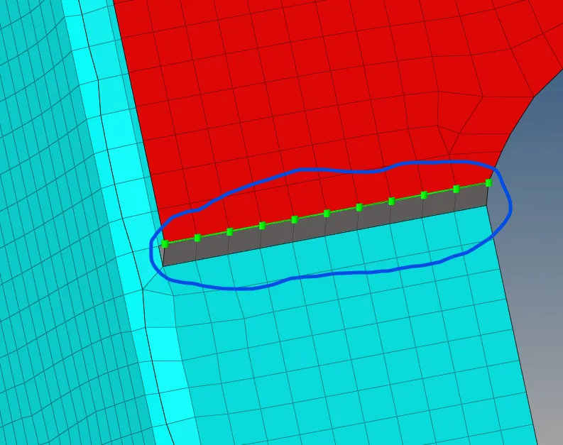
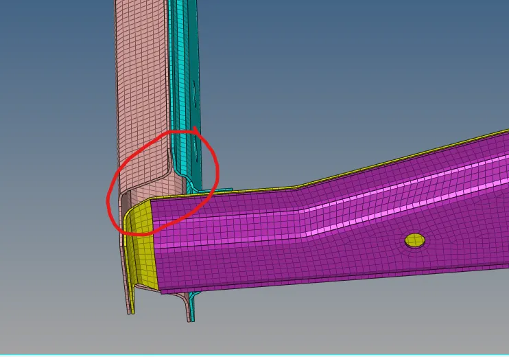
Here our connector got realized and it created the seam weld successfully. But it also distorted the mesh we have to improve the mesh in that region.
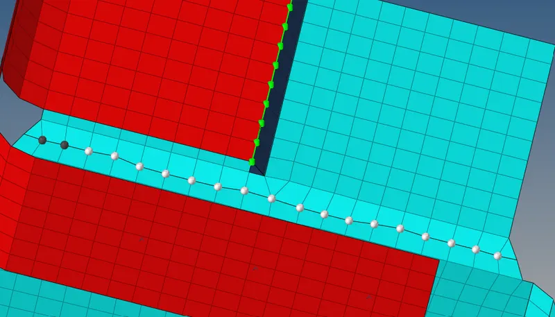
Here we use ailing node option to improve the quality of mesh
Note: when our connector not realize. it shown in yellow colour, if it is in red colour, it may be failed, we have to correct the failed element by increasing the search tolerance, But, if connector not realize then we have to realize them by using the Realize option in seam panel, also we go to the connector tab by view > Browser > Hyper-mesh > connector, in connector tab we get all the information related to the connector.
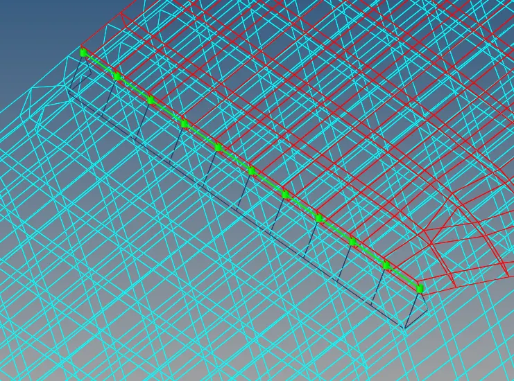
Seam weld created Successfully
- Left rail 2 & Front truss 1 (Quad-Element)
Here we have to connect the two components Left rail 2 & Front truss 1 with quad element. To, create quad element we have to option, one is to create quad element manually by using ruled option and then defining particular property to it, other option is to go to 1D > Connectors > Seam. In seam we have to define the weld location by node list, set the spacing = 5 define the tolerance value = 10, Select type as quad, after that select the components and hit the button to create Seam weld with Quad Elements
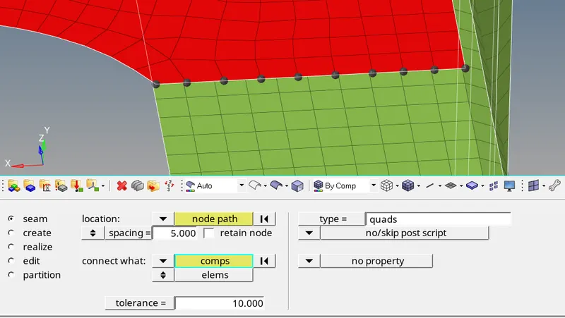
To avoid distortion of mesh you can check the retain node option
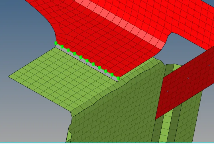
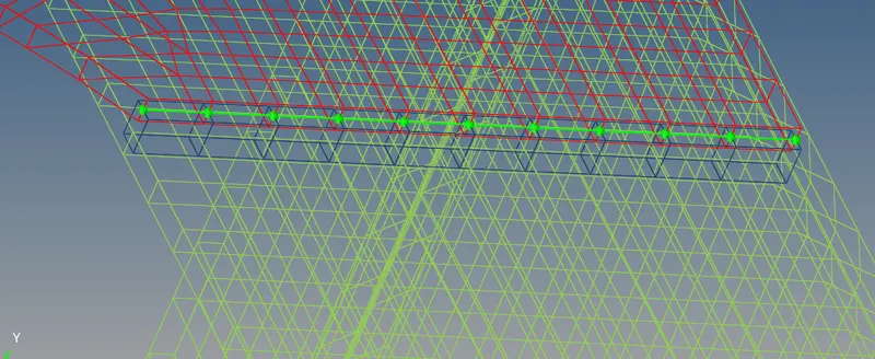
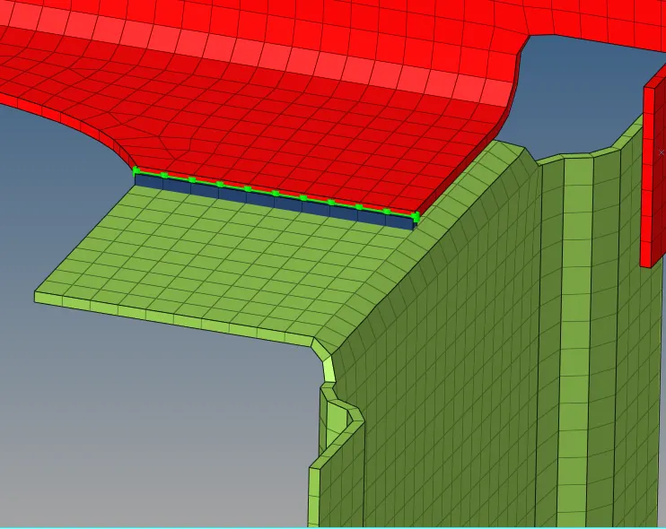
Seam weld (Quad elements)
3. Front truss 2, Front truss 1 & Right Rail 1 (Spot weld with 3 layers and 5mm diameter)
Spot Weld: Spot weld is joining technology for sheet metal (BIW) in automotive and it is fast and reliable.
We doing spot weld only when the Thickness of the part ranges from 0.9 to 3mm, even we can also do a spot weld for having 6 mm thick plates
Size of nugget depends on the thickness of sheet, in automotive industry thickness is less s we prefer diameter of 5 mm, but practically when we doing the spot weld of 5mm, the actual spot is approximately 3.5mm
Spot Weld may be
- Mesh Independent: Here we will use contacts to define spot weld between BIW sheets, no node-to-node connection
- Mesh Dependent: Here we will connect element node to node
To create Spot weld, go to 1D > Connectors > Spot, spot weld dialogue box is open, Now define the location of weld by node list, give the spacing to 5mm set the number of layer = 3(because we have 3 components to join) and define tolerance as 10, here we choose type as ACM (equivalenced-(T1+T2)/2) (it contain the Hex and rbe3 elements)
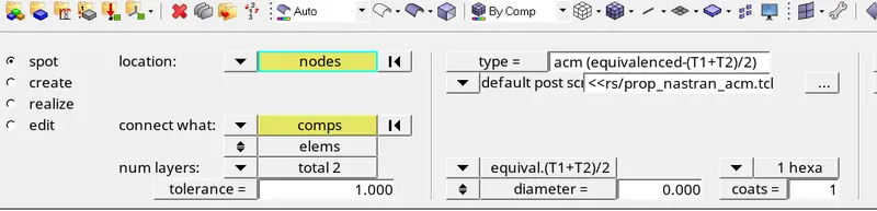
ACM (Area contact method weld): it creates aa 3Hexa element between selected elements. For load transferring RBE3 element Is created, we need to specify the spot weld diameter value, and also, we have to define the value of coats, the coats value specify the number of Hexa element stagged up into the weld.
Now select the component and hit the button to create the spot weld
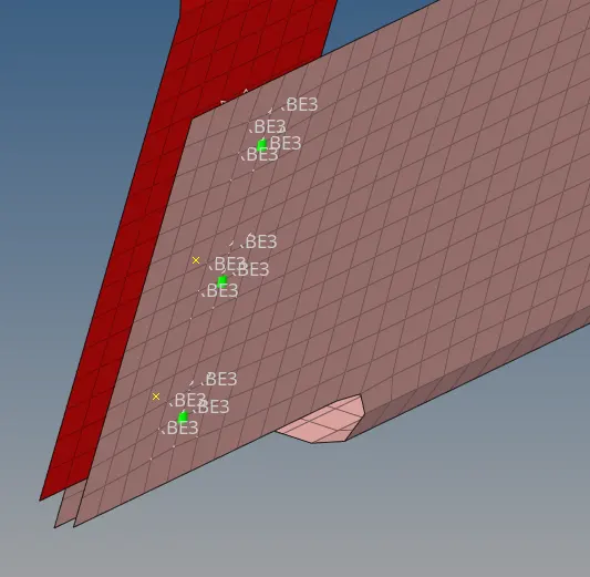
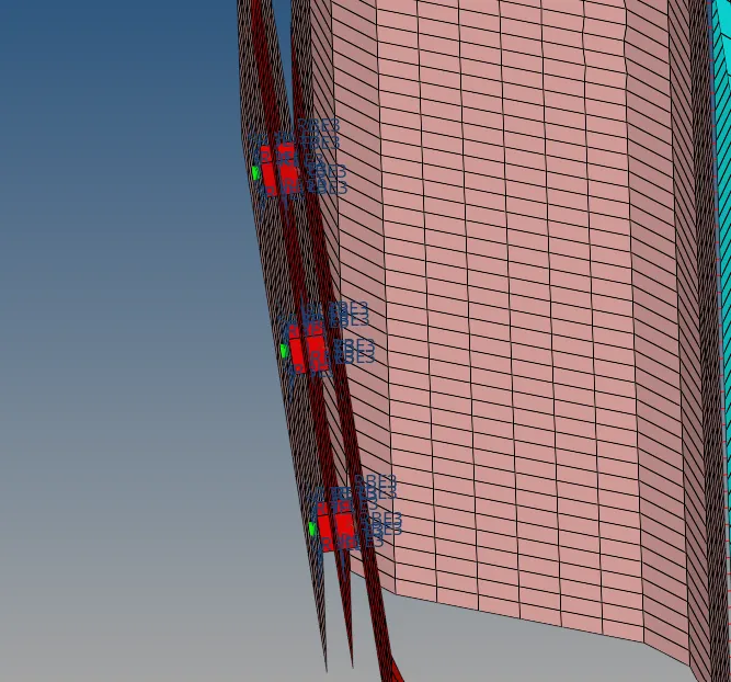
Spot weld ( Hexa & RBE3)
4. Front truss 2, Front truss 1 & left rail1 (Hexa-Adhesive)
These components were joined using the (Hexa-Adhesive) Seam welding
Hexa-adhesive connectors are used where the component is joined by using the industrial adhesives, it creates the 3D-hexa element to create the adhesives.
To apply the Hexa-Adhesive, Go to 1D > Connectors > Seam
Seam weld Dialogue box is open, select the weld location by node list, define the spacing of 5, define the tolerance value to 10, select type as hexa(adhesive-contact), also define the value of strips and coats, then select the components and hit the button to create hexa-adhesive.
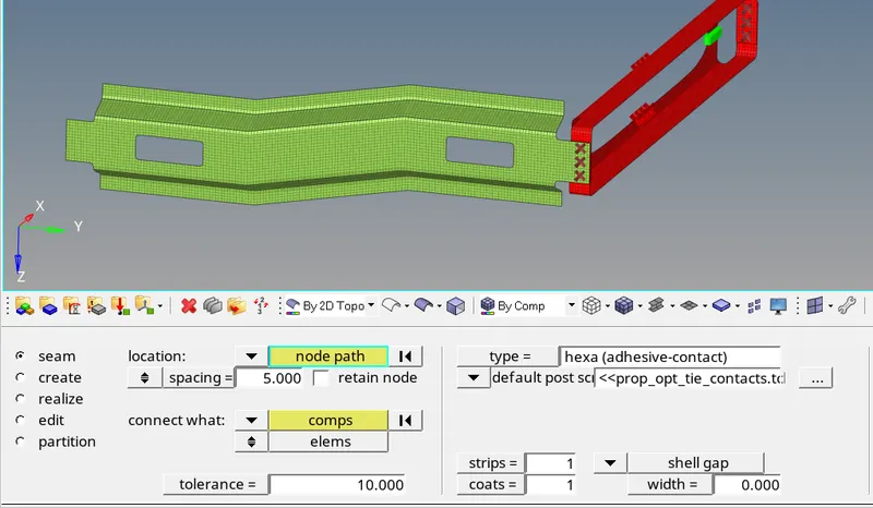
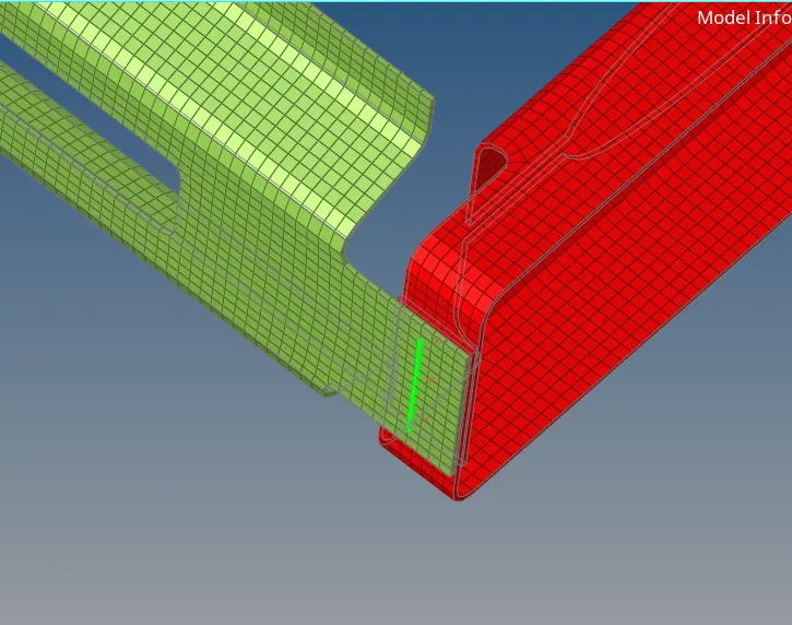
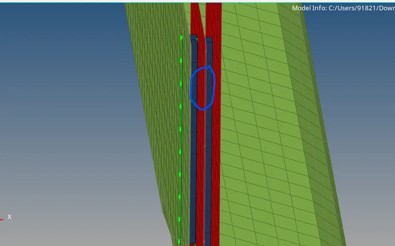
Successfully creating Hexa-Adhesive
5. Rear truss 2 & Right rail 2 (Bolt connector)
Rear Truss 2 and Right Rail 2 were joined using bolt connector at two nodes
To create the Bolt connector, go to 1D > Connector > Bolt
Bolt dialogue box is open
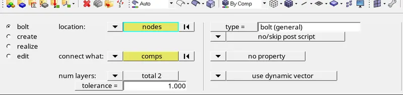
Select the location by nodes where we want to create the bolt, set the tolerance to 10, define type as bolt(general), and also “consider existing hole only” option was changed to “create hole if none”, after that select the components and hit the button to create the Bolt
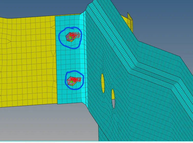
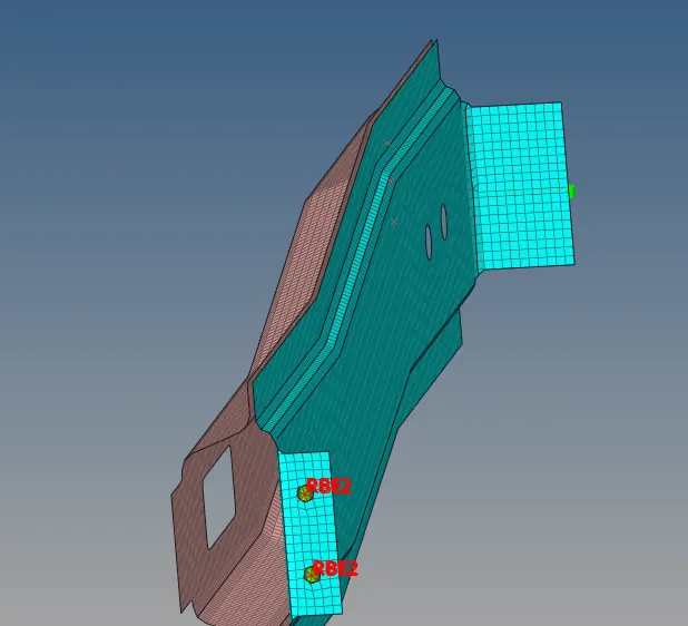
After bolt is created, it will distort the mesh, so we have to again re-mesh that region for improving quality of mesh and mesh flow.
6. Rear truss 2 & Left rail 2 (Bolt-connector)
Rear Truss 2 and left Rail 2 were joined using bolt connector at two nodes
To create the Bolt connector, go to 1D > Connector > Bolt
Bolt dialogue box is open
Select the location by nodes where we want to create the bolt, set the tolerance to 10, define type as bolt(general), and also “consider existing hole only” option was changed to “create hole if none”, after that select the components and hit the button to create the Bolt.
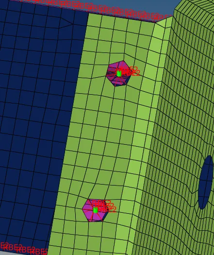
After bolt is created, it will distort the mesh, so we have to again re-mesh that region for improving quality of mesh and mesh flow.
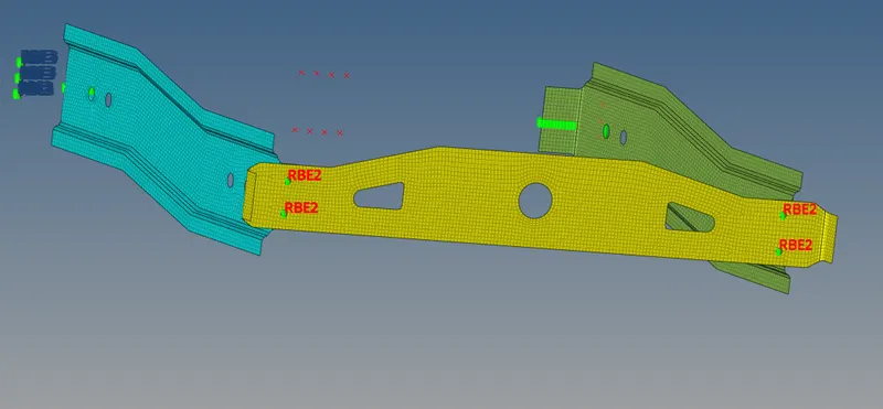
Bolt connector (RBE2)
7. Right rail 1 & Right rail 2 (Spot weld with rigid element)
Spot weld with rigid element had to be used as a connector to join these two components, this connector created RBE2 link to join the component.
To create the spot weld, the spot option was selected from the connector tab and we have set the type as rigid, specify spacing = 5 and tolerance= 10 and diameter = 5, Now select the location by node list and hit the button to create the Spot weld.
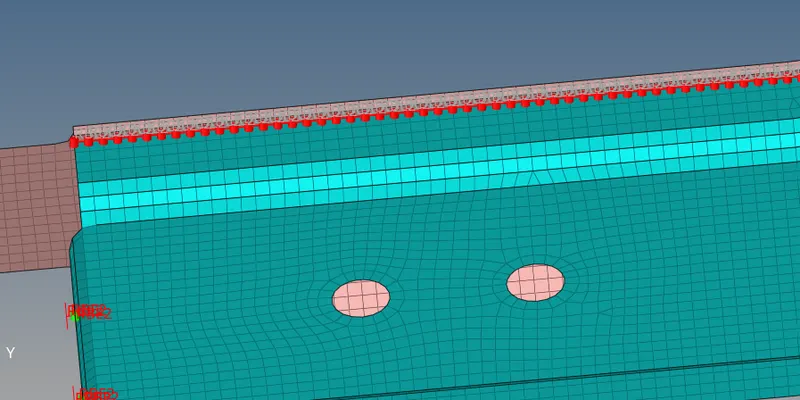
Here our connector is failed, it mainly because of the distorted mesh, means mesh pattern and number of elements is not same on both side, so again we have to mesh that region to get same number of elements on both sides. After that we again use the spot option to create spot weld having RBE2 elements.
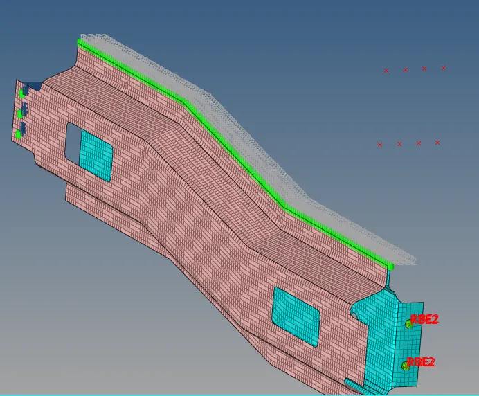
Connector realize Successfully
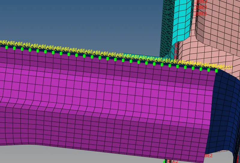
8. Left rail 1 & Left rail 2 (Spot weld with spring element)
For both the Left rails, spot weld with spring element is used, to create this similar step has to be taken as mentioned above, only one change is that instead of type as ‘rigid’ change it to CELAS (elastic) for creating spring element.
9. Other connections
There were some more areas and components which were supposed to be connected using suitable links
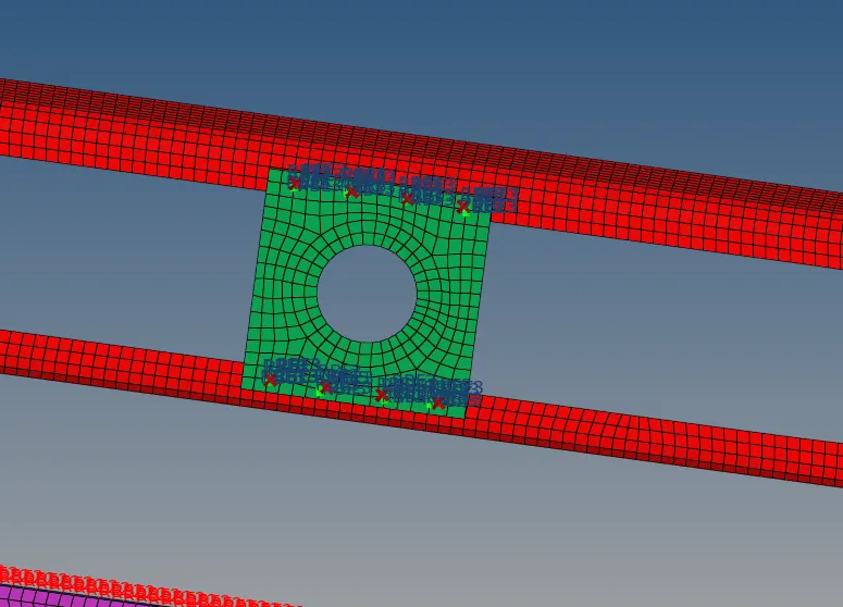
1. Here we join the Front truss 1, Front truss 2 & Reinf plate with spot weld
To create Spot weld, go to 1D > Connectors > Spot, spot weld dialogue box is open, Now defines the location of weld by node list, give the spacing to 5mm set the number of layer = 3(because we have 3 components to join) and define tolerance as 10, here we choose type as ACM (equivalenced-(T1+T2)/2) (it contains the Hex and rbe3 elements)
2. Here we join the Upper part of Left rail 1 and Left rail 2 with spring elements.
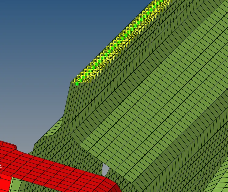
We can join the remaining parts by same connectors that we mentioned above
Note: when we created connectors, some connectors automatically create the component and property for that, make sure to look at the property and change the property as per your requirement.
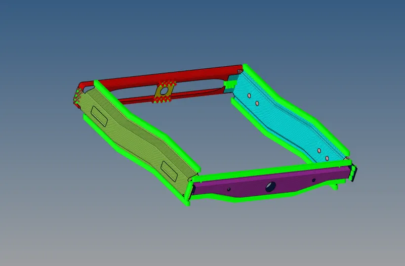
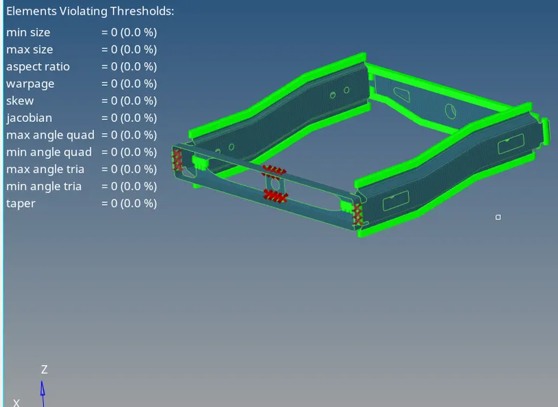
After applying suitable connector at all the components joints, the final connected model as show below
Conclusion:
Understanding about the connectors and its terminology
Understanding about the use of connector, and how to create them to join the parts of the component.
Understanding about the Debuging and Failure of connectors