Week 4-1D Element Creation Challenge
Objective: Meshing the given component with the size of 5 units. Creating 1D element on the following component with given cross-section and DOF’s
- Rod Element: Translational DOF should be constrained with RBE2 link
Cross-section: BOX
Dimensions:
a = 12mm, b = 10mm, and thickness t = 0.75mm
- Beam Element: All DOF’s should be constrained with RBE3 link.
Cross-section: I-Section
Dimensions:
Dimension a = 8mm
Dimension b = 10mm
Dimension c = 8.5 mm
Thickness t1 = 0.75mm
Thickness t2 = 6mm
Thickness t3 = 6mm
- Bar element: Constraint only x and y DOF’s with RBE3 link.
Cross-section: X-Section
Dimension DIM1 = 5mm
Dimension DIM2 = 12mm
Dimension DIM3 = 10mm
Thickness DIM4 = 12mm
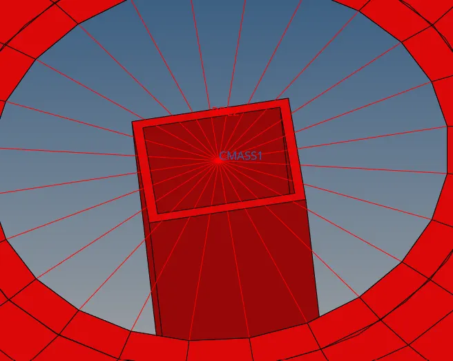
- Apply the mass of magnitude 10 with the RBE2 links
- Join the two components with the Spring Element.
Model:
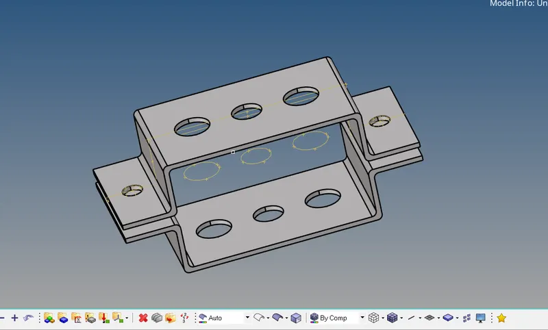
Mid-Surfacing:
Why we create the Mid-surface?
While doing 2D meshing we extract the mid-surface from the model. Mid-Surface means the surface between the two surfaces. 2D meshing is carried out on the mid-surface, because mathematically element thickness we assigned half in +Z axis (element top) and half in -Z axis (element bottom). Hence for appropriate representation of geometry via 2-d mesh it is necessary to extract the mid-surface & generate nodes and elements on the mid-surface. We try to create the shell elements (one dimension i.e. thickness is significantly smaller than the other dimensions) which is 2D representation of 3D elements. Mid-Surface meshing is used when the geometry thickness is very small as compare to its length and width, so we are generally used in most of industries where structure is made up of sheet metals and plastic etc. In that cases we use 2D elements instead of 3D elements, hence by adopting Mid-Meshing number of nodes are decreases and also computational time decreases.
Note: If we extract mid-surface by using Auto-mid-surfacing option make sure that geometry having ideally constant thickness for better result.
Procedure:
- To open the geometry file, go to Import option and then go to import geometry.
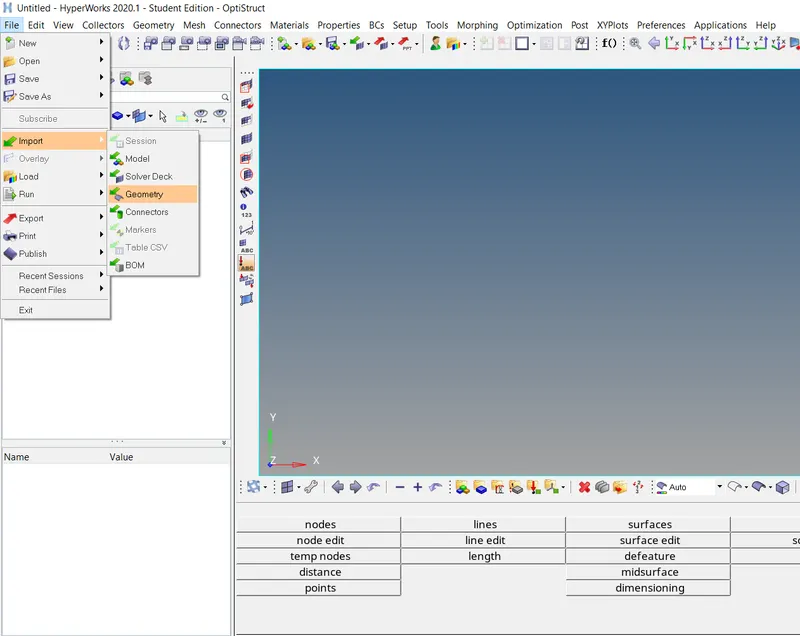
Select the geometry file format that you have and import them
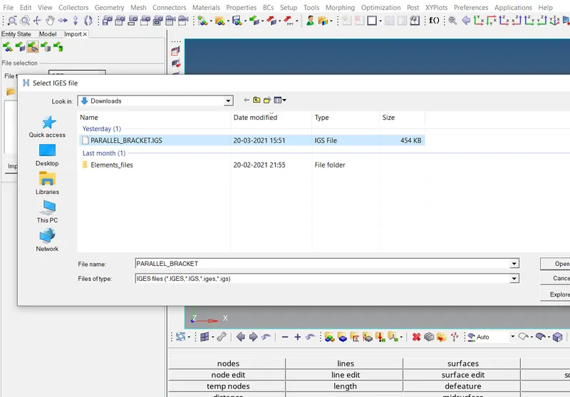
Now click on the file and then click on import option to import the geometry. Geometry will appear on the screen, if you can’t see on GUI, go for fit option or either press F to fit the geometry according to the co-ordinates.
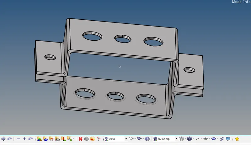
PARALLEL BRACKET
To create a mid-surface, go to Geometric panel and then go to mid-surface option.
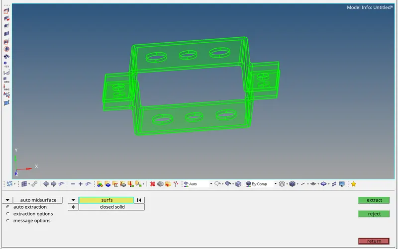
We have various option to create the mid-surface
Extract Option:
Offset + Planes + Sweeps
Offset + Planes
Offset
Skin-offset
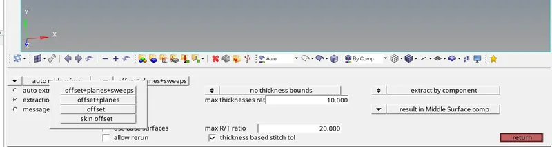
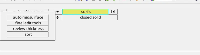
We can use these options to create the mid-surface by using auto-mid-surface option, we can also do manual mid-surfacing by using final edit tool option.
Extraction by using Offset + Planes + Sweeps
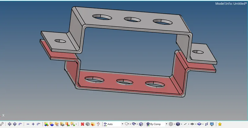
Note: To getting clear view about mid surface, increase the transparency of the mid-surface.
Extraction by using Offset + Planes
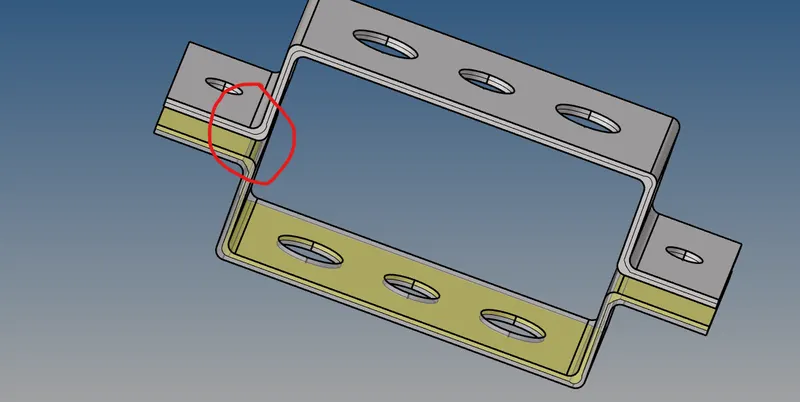
Here edges are not extracted clearly
Extraction by using Offset only
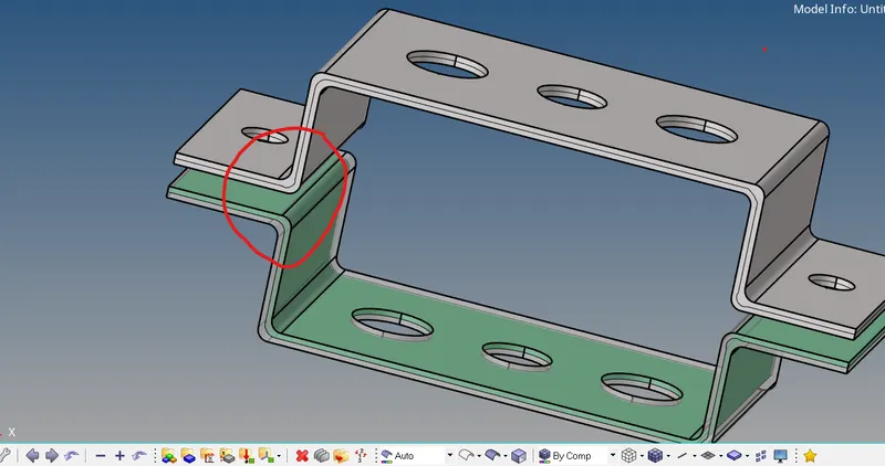
Extraction by using Skin-offset
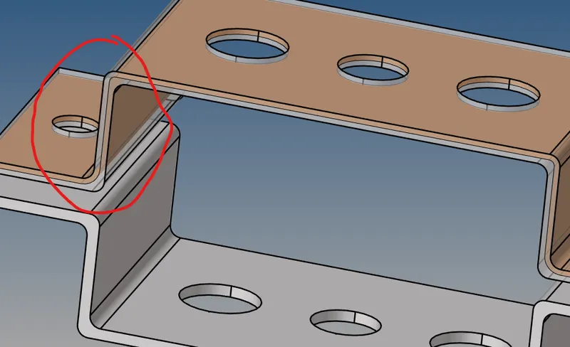
We can also extract mid-surface manually by using the final edit tool option.
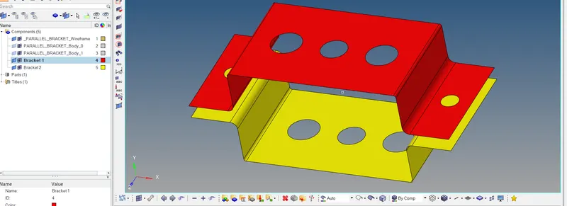
Extract mid-surface one by one of both the component and then give them particular name, by extracting the mid-surface of both the component in one time create complexity during assigning properties to the component.
Before doing mesh, we have to create the washer-split around the holes and also split the surface for getting better mesh. To create washer split go to quick edit option in Geometric panel.
Note: Also check out for the geometrical errors if any like free edges inside geometry, duplicate surfaces etc.
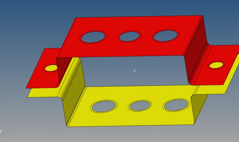
Now to create mesh go to 2D panel and then go to auto-mesh option and enter the element size of 5 units
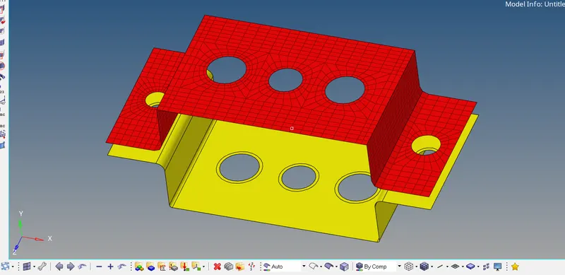
Now meshing of one bracket is completed, now reflect the same mesh on second Bracket. For reflecting go for tool page and then go to reflect option.
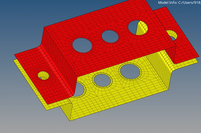
Now our meshing is completed
Now we assign material to the entire component. To assign material go to material option in tool bar, also we can assign material by right click and then click on material option.
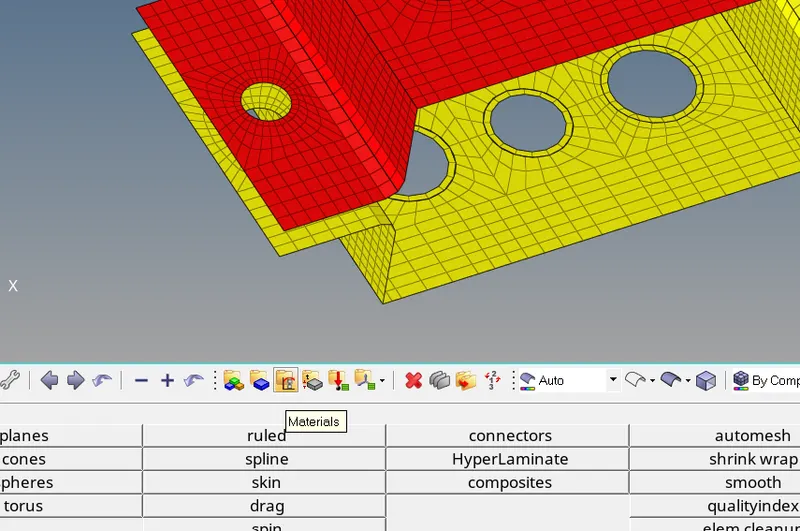
Here we assign the material as Steel and card id MAT1 for steel, and after material is created assign it to the component
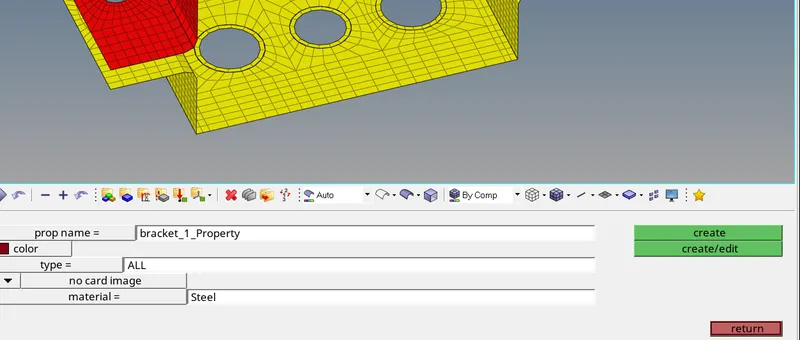
Also check for other properties of steel in create & edit option
After creating the material collectors, we create properties to the component.
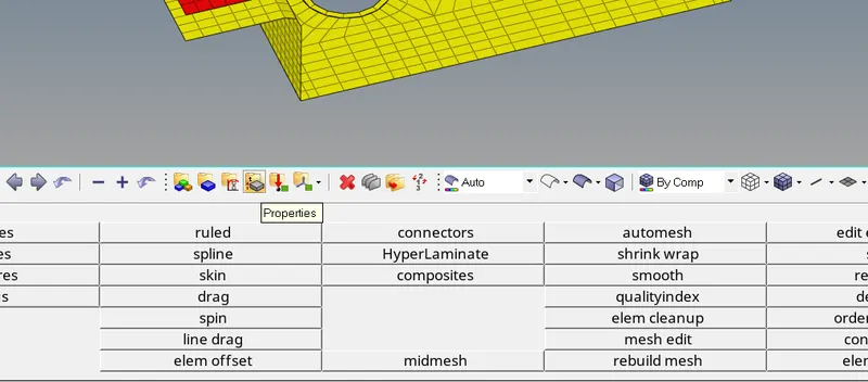
Give them a name and assign material as steel that we created previously.
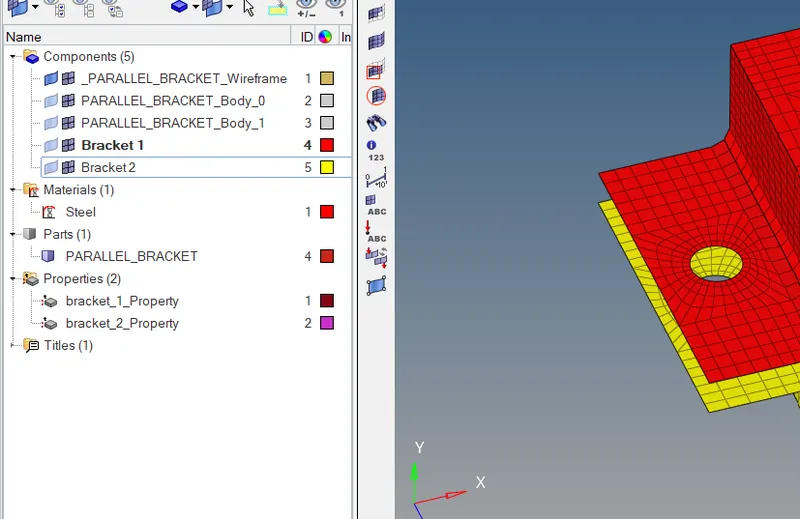
Here two properties are created for Bracket 1 and Bracket 2, also we can delete the body of the bracket if not require. After that we assign the card image as P-SHELL and thickness to represent the 3D geometry
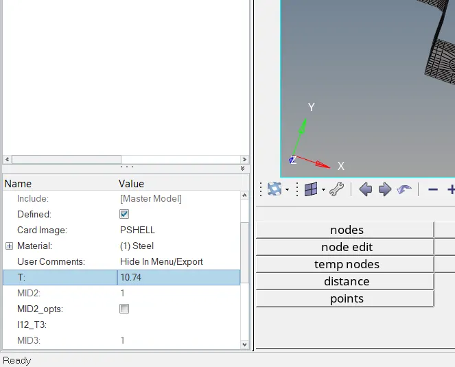
Assign properties to the brackets.
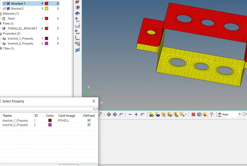
To see the thickness of the Bracket, go to 2D Detailed representation option.
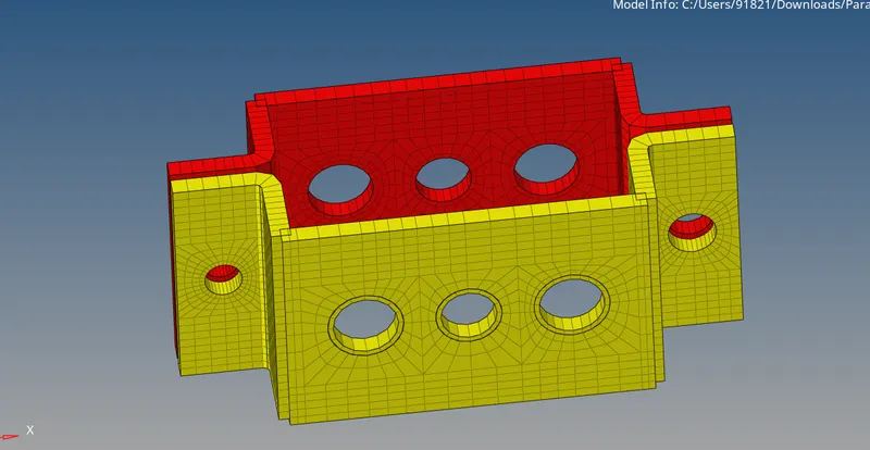
Note: Here we avoid the fillet of the bracket due to this we get some error.
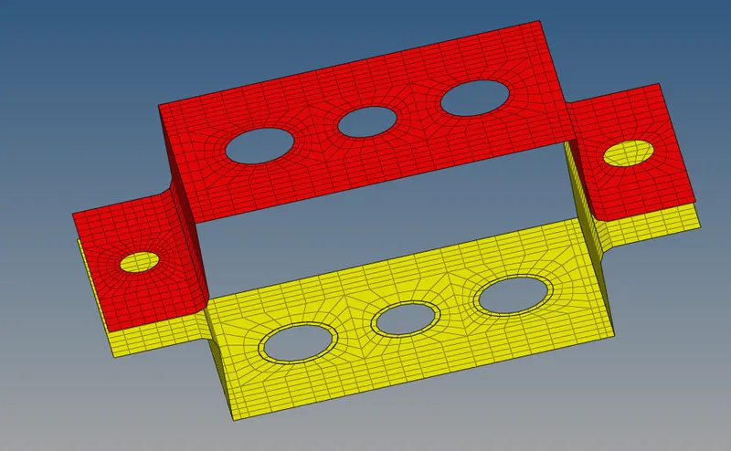
Creating 1D elements on this component with given cross-section and DOF’s
- Rod Element:
Translational DOF should be constrained with RBE2 link
Cross-section: BOX
Dimensions:
a = 12mm, b = 10mm, and thickness t = 0.75mm
Before creating rod element, we firstly created a RBE2 and RBE3 links
RBE2 vs RBE3
RBE2 element is the element that having infinite stiffness, it means node will not move at all and it is the stiffest element in the hyper-mesh, also load distribution is same irrespective of the distance of element from the independent node. Whereas RBE3 elements are those elements whose nodes are not fixed they can move left right up down, also here load distribution is also not uniform, node which is closer to the element will have more load as compare to the node which is away from the element.
Now to create RBE2 element or link go to 1D panel and then click on RBE2 option, in hyper-mesh the RBE2 is written or shown as a Rigid element. Their translation DOF’s should be constrained by giving DOF’s along x, y and z axis.
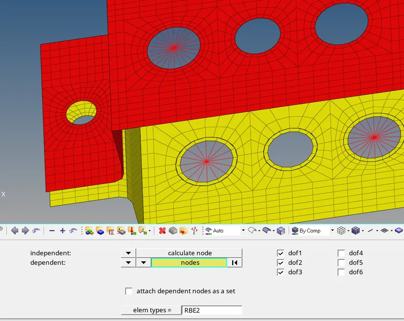
RBE2 link is created because it is a cluster of RBE2 elements
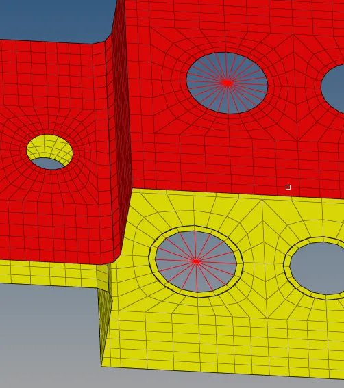
In similar way we can create RBE3 elements and link with all DOF’s should be constrained.
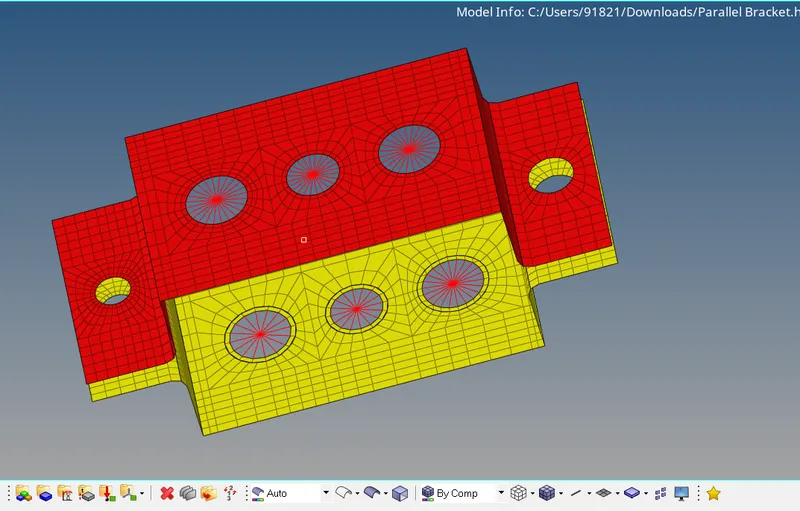
Both RBE2 link and RBE3 link will be created.
To Create ROD Element:
Step1
To create 1D element we use the MHPCLL technique which is used for the performing the linear static analysis with 1D element.
To create 1D element we use the MHPCLL
M stands for Material collector
H stands for Hyper Beam
P stands for property collector
L stands for load collector
L stands for load steps
Note: we previously assigning the material for Brackets, same material we assigned for ROD element.
Step 2
Now we can define the cross-section of the rod in hyper-beam
Cross-section: BOX
Dimensions:
a = 12mm, b = 10mm, and thickness t = 0.75mm
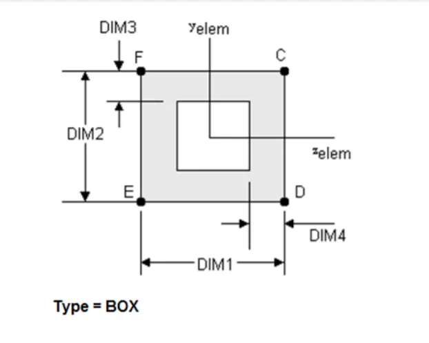
For defining cross-section go to 1D panel and then go to Hyper-beam option.
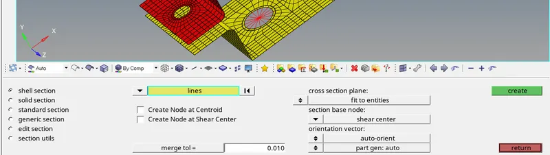
Go to standard section and then click on box option, Hyper-beam GUI has been opened.
Give them the required dimension as in our problem
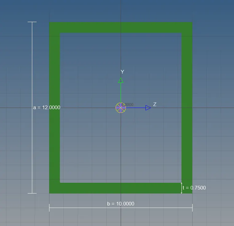
Now we define the cross-section, after that we come back to our Hyper-works GUI
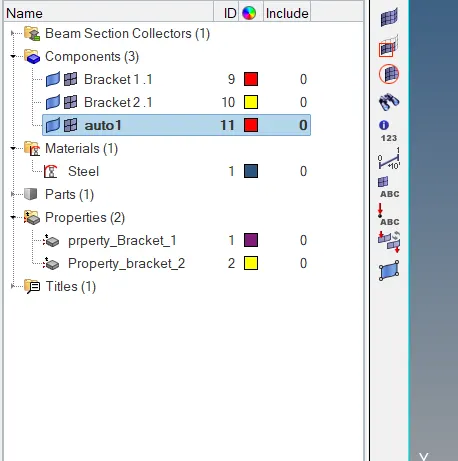
Now here Beam Section Collector is created
Step 3
P stands for property collector, we creating property collector for Rod element. Same process is used to create the property collector.
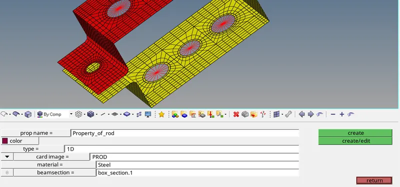
Step 4
Creating a Rod element using Rod option in 1D panel and assign property to them.
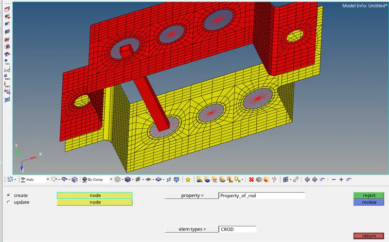
ROD ELEMENT IS CREATED WITH BOX CROSSSECTION
Beam Element: All DOF’s should be constrained with RBE3 link.
Cross-section: I-Section
Dimensions:
Dimension a = 8mm
Dimension b = 10mm
Dimension c = 8.5 mm
Thickness t1 = 0.75mm
Thickness t2 = 6mm
Thickness t3 = 6mm
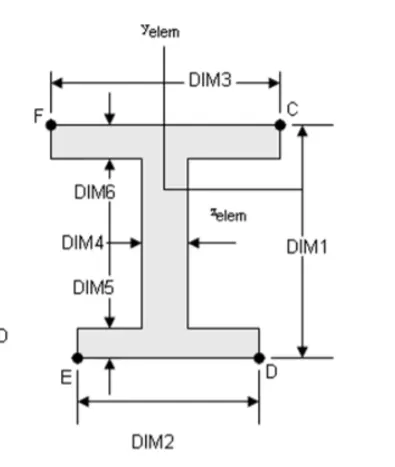
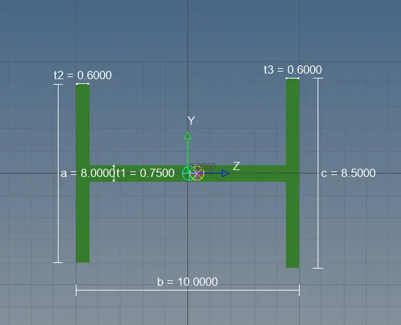
In a same manner we give dimension to the Beam element and create property to them.
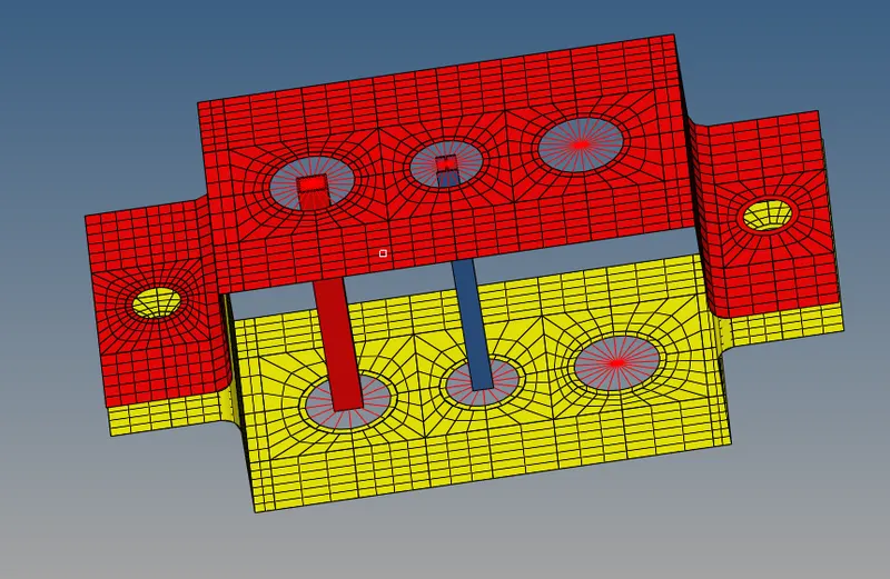
To create a beam, go to 1D panel and then click on bar option to create a beam select the element type as C-BEAM to creating a Beam.
Cross-section view:
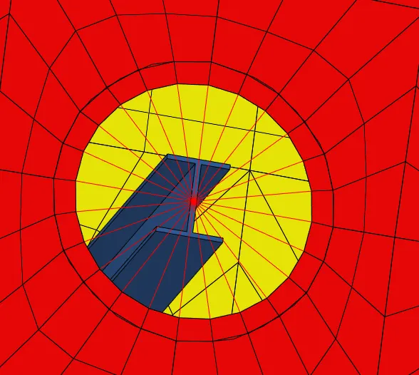
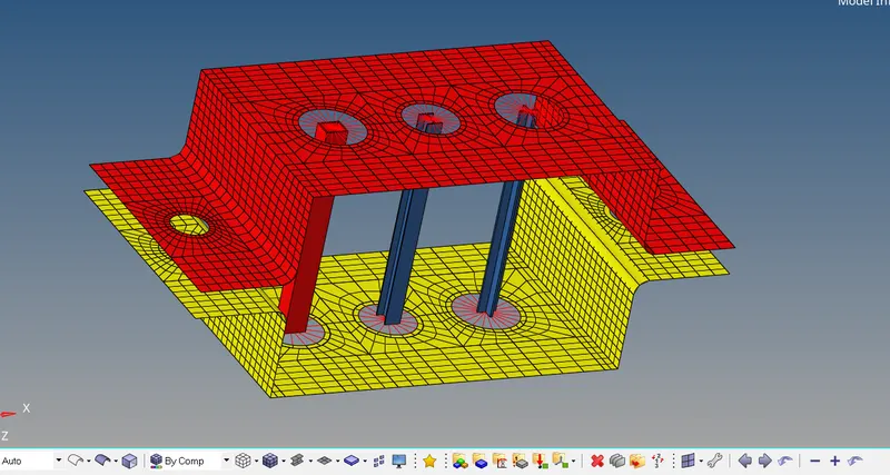
Beam of I section has been created
Bar element: Constraint only x and y DOF’s with RBE3 link.
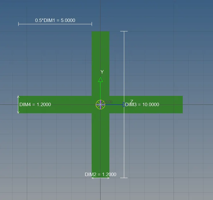
Cross-section: X-Section
Dimension DIM1 = 5mm
Dimension DIM2 = 12mm
Dimension DIM3 = 10mm
Thickness DIM4 = 12mm
We get X cross section in the standard section of the Opti-struct libraries.
Now after defining cross-section, creating a property collector and assign them to the Rod element.
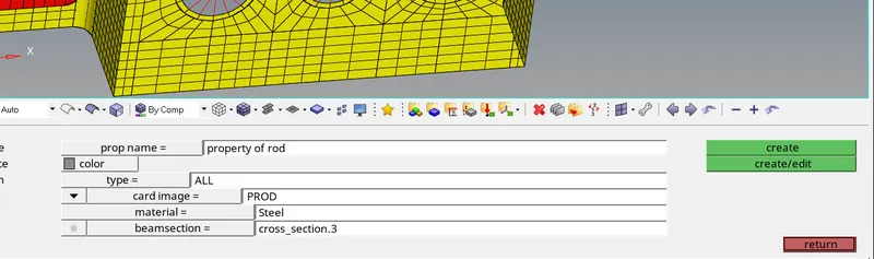
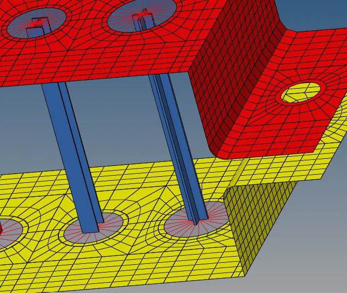
After creating property create a Rod element by using 1D panel.
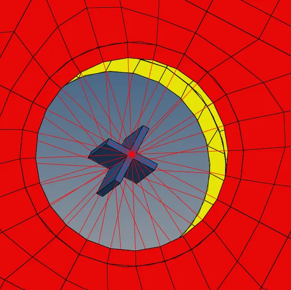
Cross-section view:
Difference between Rod Bar and Beam element
ROD is 1D element only carry either Tension/Compression or having 2 DOF’s, example shafts is subjected to Tension compression.
Where as Bar is 1D element with having 6 DOF’s and it can be subjected to multiple loading but it can be applicable for symmetrical cross-section, Beam is same as bar but it also supports un-symmetric section. Beam element is recommended for symmetric as well as un-symmetric cross-section as it takes into account shear center. Bar element have limitation of shear center and hence it is not recommended for un-symmetrical section.
Apply the mass of magnitude 10 with the RBE2 links
To apply the mass, go to 1D panel and then click on mass option to apply mass on the nodes.
Join the two components with the Spring Element.
To create a spring element, go to 1D panel and then go to spring option
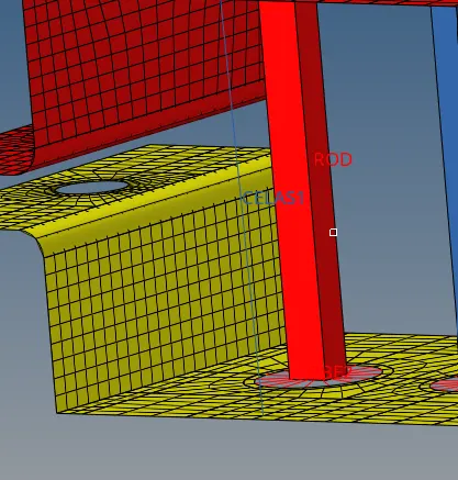
Spring with element type CELAS1
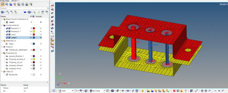
Learning Outcome:
Here we are understanding about the Mid-Surface extraction and its importance.
Understand about 2D shell element and its importance.
Understand about 1D elements and its meshing and how to create them.
Understand about creation of 1D element cross-section by using Hyper-Beam.
Understand about the DOF’s of the element and how it can affect the result.
Understand about spring and mass element.