Week 6 - Creating connection for Rear door
AIM:
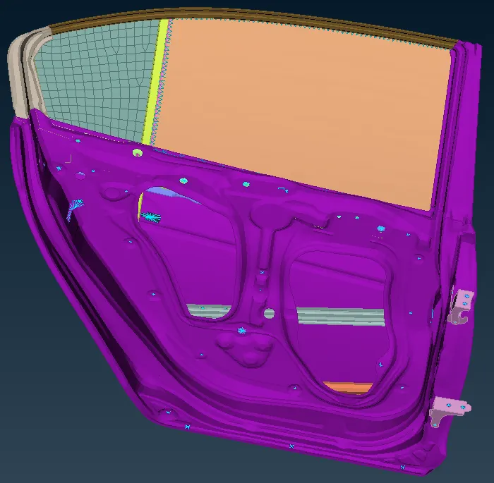
To perform different types of 1D connections to the Rear door FE model in order set it right for further solving The procedure is described below for the same.
Note: All the connections are to be done in NASTRAN Deck as the solving will occur f Noise, vibration, and harshness (NVH) calculations
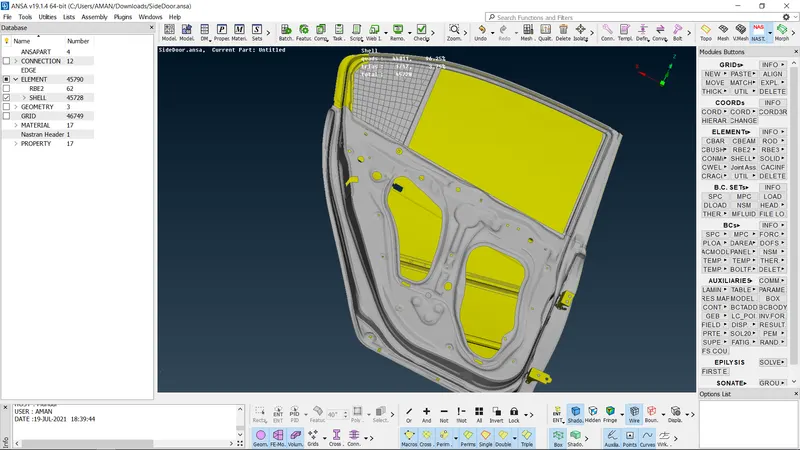
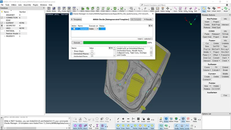
Then the connection is deployed at the door handie region.
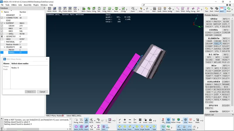
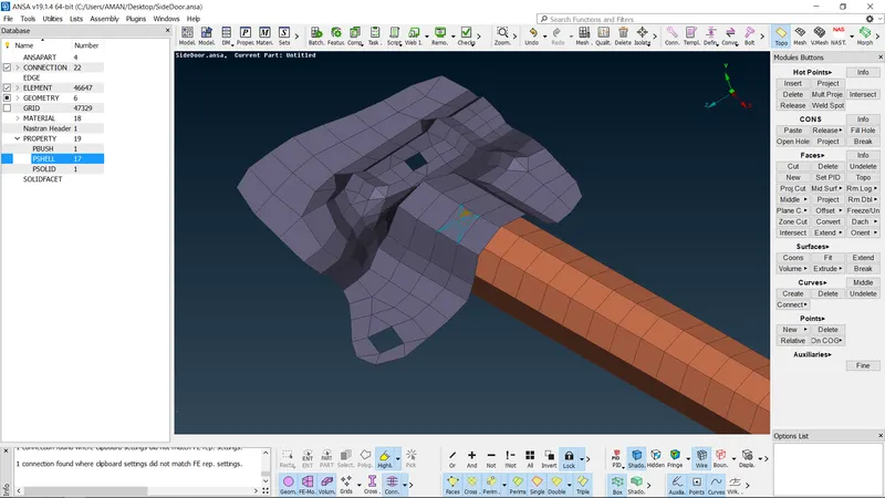
Initially, the RBE2 elements with many nodes option is used to connect all nodes at the perimeter of the handle. Inoder to possess the rgid nature.
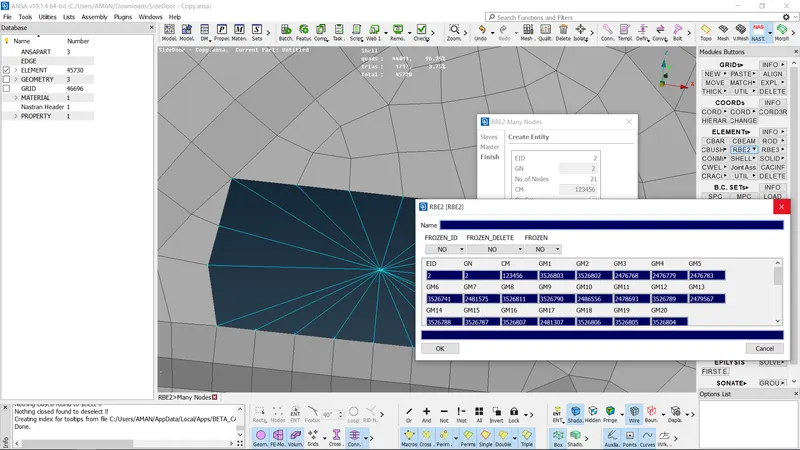
Then a RBE2 element with many nodes is used to connect the both master nodes. After connecting, it appears
Note The reason behind using RBE2 with many nodes rather than RBE2 with two nodes is. to have a master node after connecting those two master nodes. But in case of RBE2 with two nodes there will be no master node after connecting those two portions
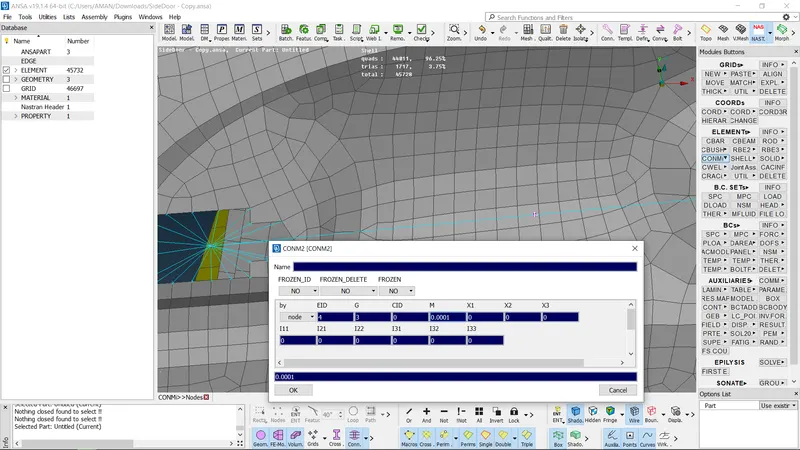
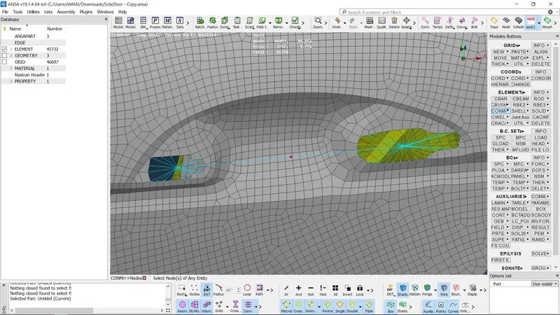
Then to represent the weight of the door handie, as in case of real world scenaria. The mass can be assigned by using the "CONMI CONM2 Nodes in NASTRAN deck module.
A weight is assumed as 100 g and entered as "0.001 tone"(Which will be in the form tonns). And this is applied to the master node at the center.
After assigning the mass at the center master node, it will be represented as highlighted
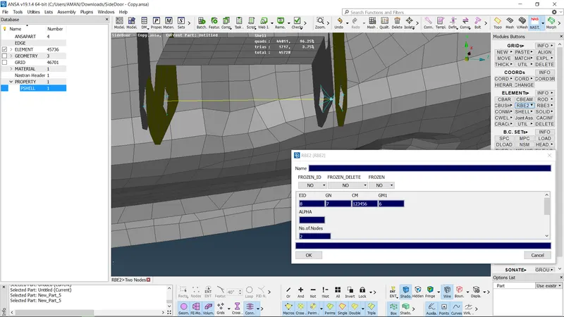
- A) MANY NODES AND TWO-NODE RBE2's ELEMENTS They are the building blocks of connections that are used to rigidize parts, These elernents can be optimized on the levels of nodes, physical connections, degree of freedom arrested. etc. These elements connect slave nodes with one master node. An example of a basic many-node RBE2 is shown below.
FIG Slave nodes are selected.
FIG To connect the outer door panel with another long part two-node RBEZS are used on all four comes
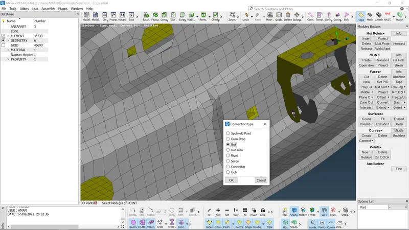
FIG 3 Number of RBE2S are created by joining four master nodes of the many node RBE2
B) Bolt Major steps include point realization, entity conversion to bolt, connection realization Steps are elaborated along with the figure below
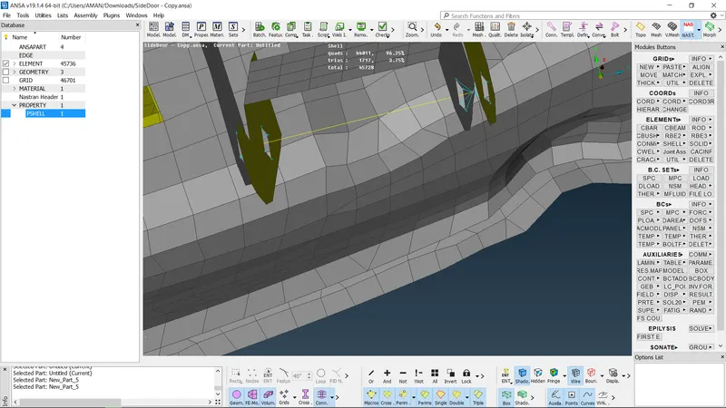
FIG. Sub-part assembly before PIID set for all the different parts
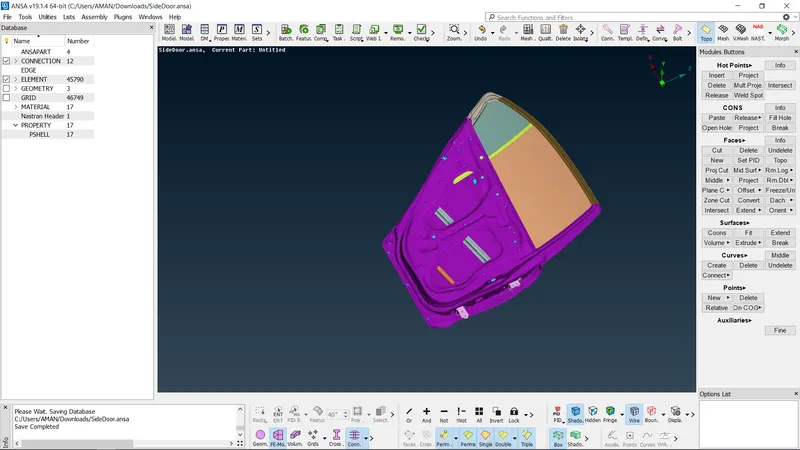
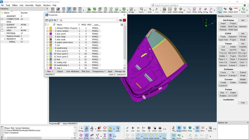
FIG: PID set for all the different parts of the sub-assernbly.
- E) CBUSH CONNECTIONS
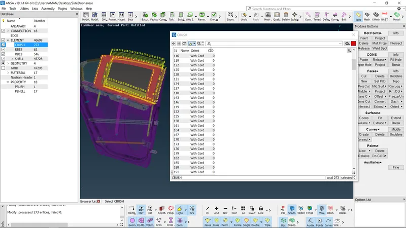
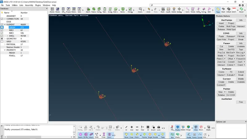
In an automobile door assembly, connections with respect to Glass are crucial In practical application glass in a door assembly moves downward but while doing connections for NVH solving they need to be rigidized. So glasses are connected using CBUSH elernents as they hold the property like stiffness and damping coefficient, etc. They are connected with weatherproofing strips
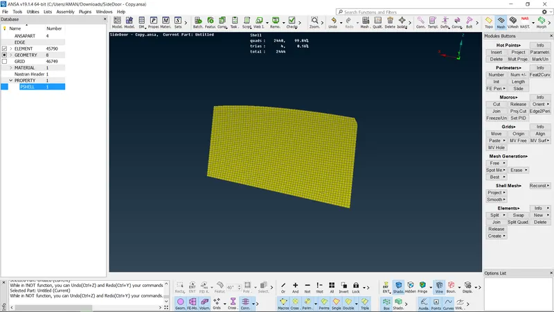
Typical steps include conversion of glass periphery into curves, curves conversion to spot lines, realizing connections between parts with FE Rep style as RBE3-CBUSH-RBE3, and PBUSH ID is also created
FIG Perimeter of the mirror is converted to a curve using "FEATZCURVE
FIG Individual curves are converted to Spot Line.
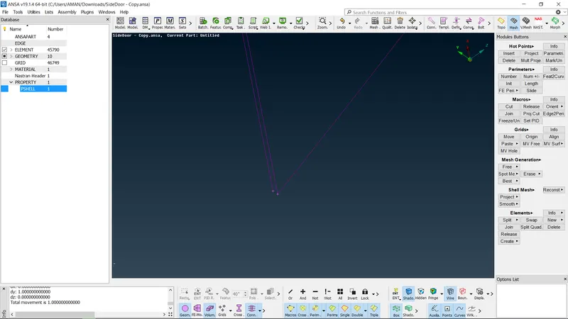
FIG: Individual sliding glass and outside door panel is connected using RBE3-CBUSH-RBE3 as FE Rep style and a new PBUSH ID is created with stiffness value input.
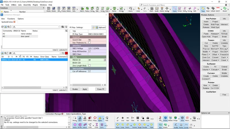
FIG: Stiffness value input
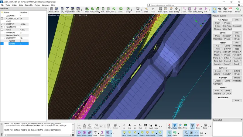
FIG: CBUSH is realized between Sliding glass and outside door panel.
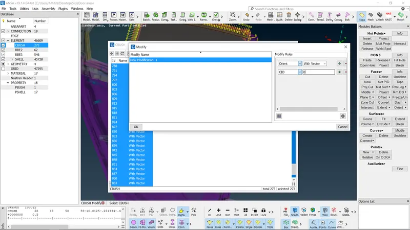
NOTE: After the glasses are fixed, the orientation of RBE35 is changed to global coordinates.
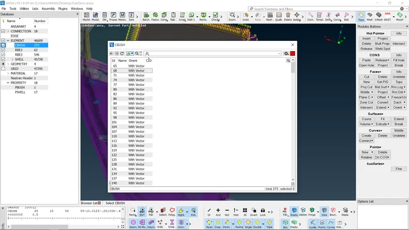
FIG: Coordinate ID is set to zero. Using the connections discussed above rest of the Automotive door assermbly is connected to each other Making the model complete for further NVH solving
- C) SPOT WELD
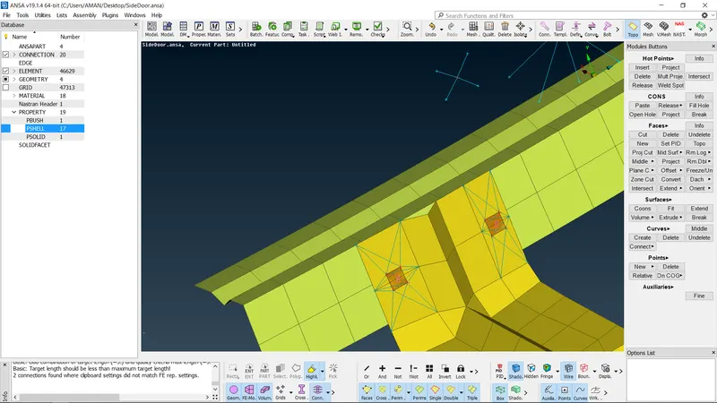
Spot weld is realized where parts are close to each other, points are converted to spot weld connections with allowing parts to connect, FE REP is used as RBE3-HEXA-RBE3 and PSOLID ID is used for SPOT weld body.
FIG In the figure above, structure elernent 2 and Sliding Glass guide are connected using Spot weld and FE rep type as RBE3-HEXA-RBE3. Later solid Id will be made for the Hexa element which will complete the Spot weld connection
FIG Spot weld is realized between Structure element 2 and Sliding glass guide
- D) CONCENTRATED MASS ELEMENTS
In many places in an automobile door assembly, for accessories like side mirrors, handlebars, etc slots are provided for assembly In such known cases, slots are connected with many Nodes RBE2S and a concentrated point mass is allocated on the COG of the elements replacing the original unavailable components.
CONCLUSION
- While preparing any assembly for FEA analysis, physical connections must be provided to represent the actual conditions
- Connection types include seam welds, spot welds using elerments like ConMass. RBE2S. RBE3S, CBUSH, etc
- ANSA offers various corinectioris depending upon the deck types
- ANSA provides easy access to review and access all the element types