Week 9-Creation of 1D Connectors Challenge
Objective :-To Create 1D Connectors in the given component in Hypermesh.
Cad model image :-
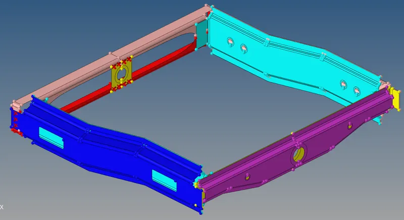
Procedure :-
Connectors : They are geometric entities ( not FE ) primarily used to create spot and seam welds but also used to create adhesives , bolts , and masses They are simply a database of information defining specific requests for connections at specific locations . They are a medium to create both solvers independent and / or solver dependent connections between geometric and / or FE entities .
Import the Model in Hypermesh -Visualize the components
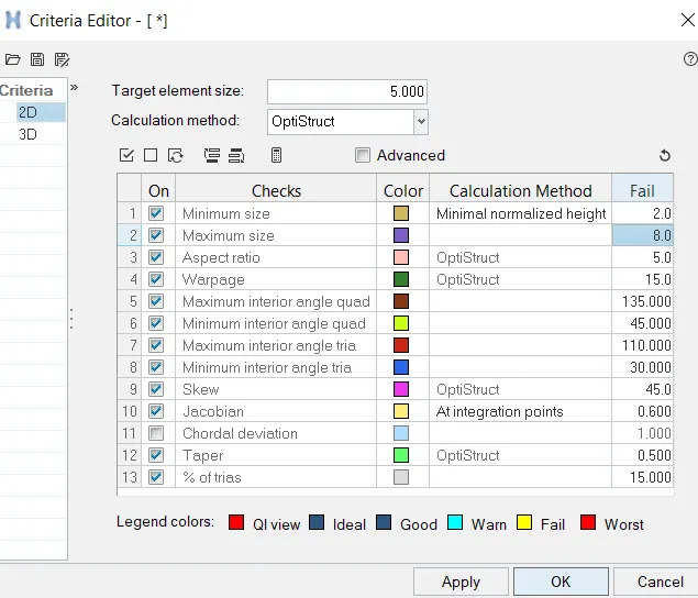
Create the Criteria Parameter file as per the given Quality Criteria.
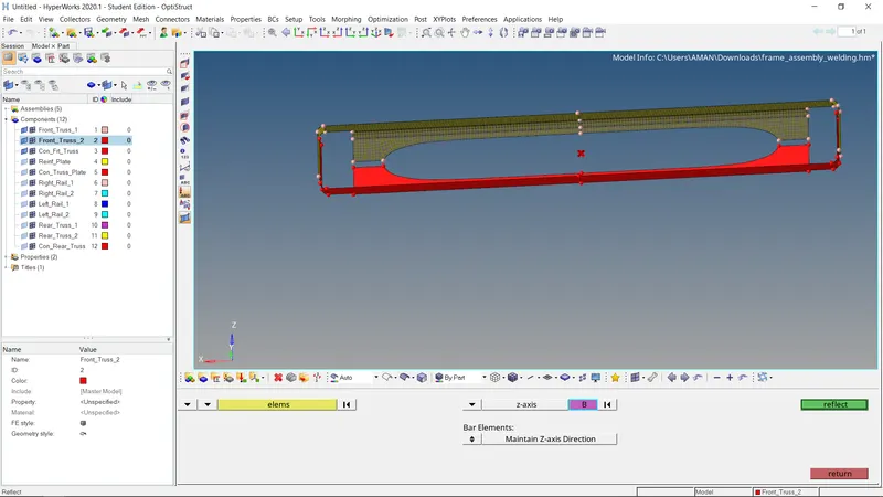
- Mesh all the components using the automesh option from the 2D panel, keeping the element size to be 5 unit
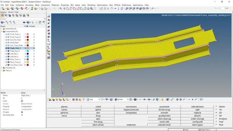
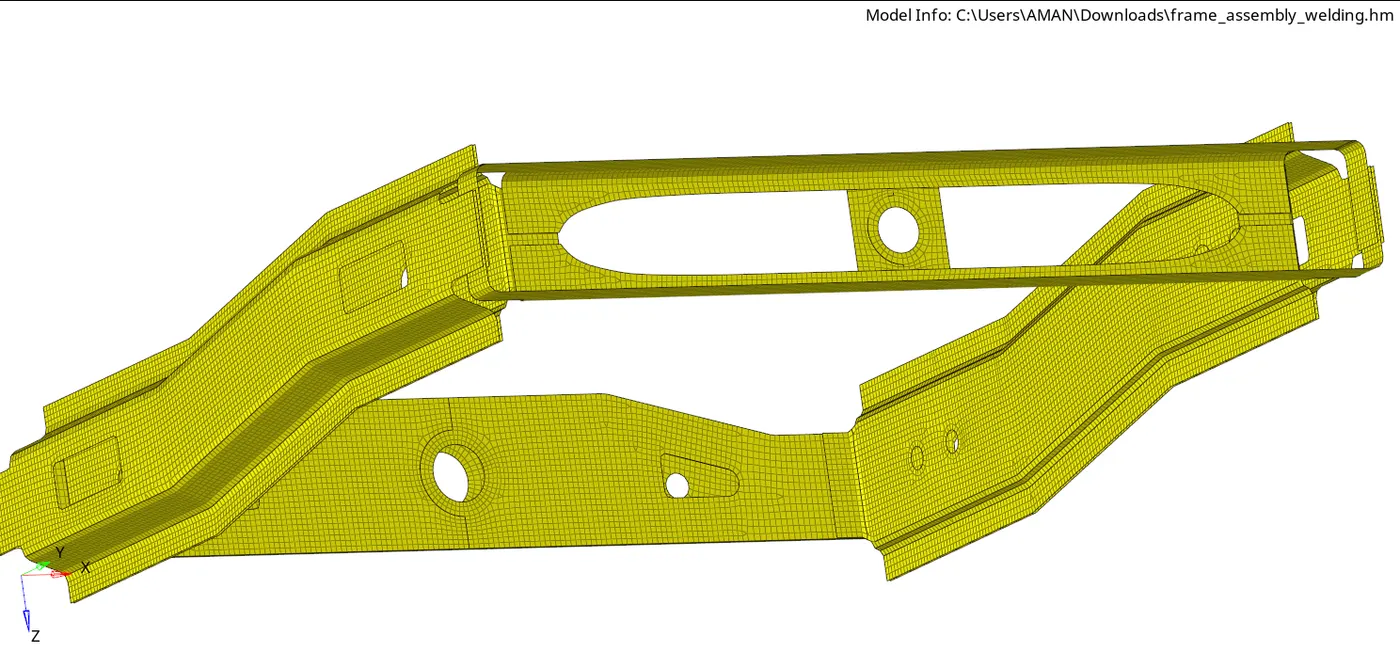
-After meshing check for the 2D mesh quality and repair the failed elements.
- Now as per the requirement, creating connectors on different components.
- Right Rail 2 & Front truss 1:- Seam-Quad(angled+capped+L)
- To create these connectors, we will go to the Connectors tab in the 1-D panel, then select the seam tab
- Here from location select Nodes, spacing to be 5, tolerance can give 10, to avoid the failure of connectors.
- Now select the 2 components(Right_Rail_2 & Front_truss_1) between which the connector is to create and select the Type Seam-Quad(angled+capped+L).
- Then select Imprint in Quad Transition and hit create
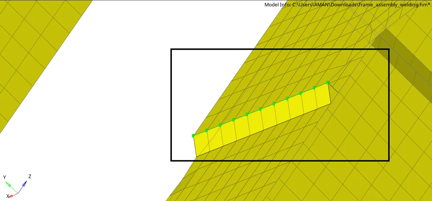
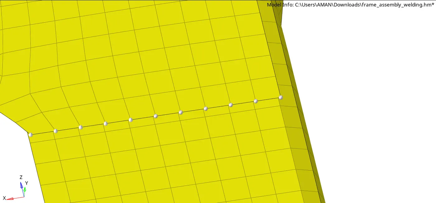
2. Left Rail 2 & Front truss_1:- Quad elements - For this connection follow the same procedure for components (Left_Rail_2 & Front truss_1) and select the Type to be Quad in Seam welding option, then hit create.
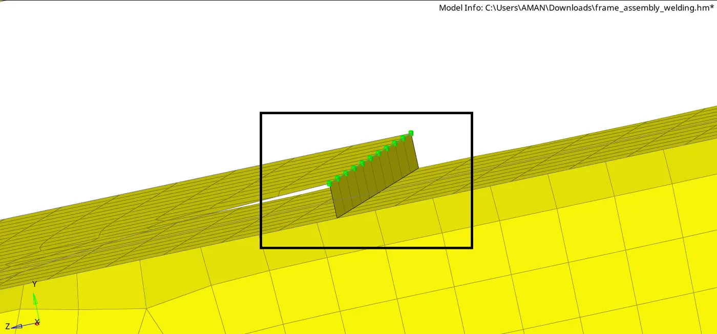
- Front truss_2, Front truss 1& Right Rail 1:- Spot weld with 3 Layers'and 5 mm Diameter
- To create a Spot weld, go to the connector in the 1-D panel, then select the spot tab
- Here from location select Nodes, toierance can give 10, to avoid the failure of connectors, then a select the number of layers to be 3 & Diameter to be 5 as required.
- Now select the 3 components(Front_truss_2, Front truss_1& Right Rail_1) between which the connector is to create and select the Type- weld, and create.
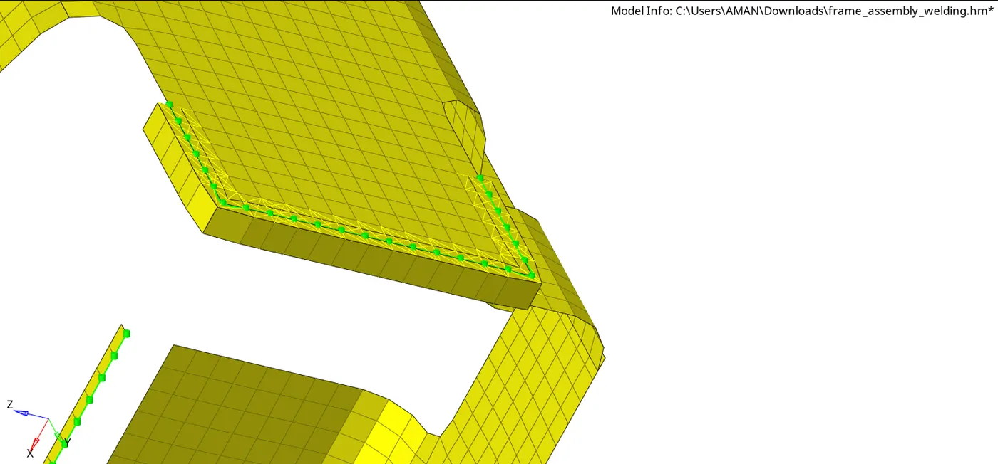
- Front truss_2, Front truss_1 & Left Rail 1:- Hexa (Adhesive)
- For this connection, we can create it from the area option, in the connectors in 1-D pannel
- In this, we need to select the element where we have to connect with adhesive, then select all the components (Front_truss_2, Front_truss_1& Left_Rail_1).
- Select the Type as Adhesive and hit create.
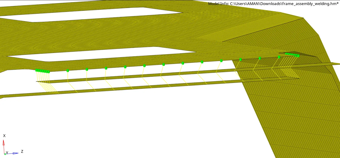
5 Left Rail 1& Left Rail 2:- Spot-weld with Spring Elements
- For the above 7 and 8 connections, we will follow the same procedure as done before in spot weld, we will select the components accordingly and in the type option, we need to select the rigid/spring elements as required for different components respectively.
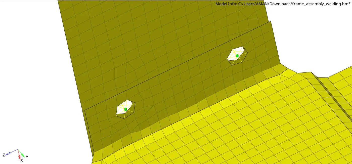
6 Rear_truss 2 & Left Rail 2:- Bolt Connector
- For the Above 2 bolt connection, we will go to the bolt tab in connectors.
- Here select the Nodes location where the bolt is to be created, then select the components(Rear truss_2 & Right Rail 2), tolerance to be 10 to prevent failure of connection, type to be bolt(general).
- Now, here we don,t have an existing hole here in these components, so we should select the create the hole, if none option and hit create.
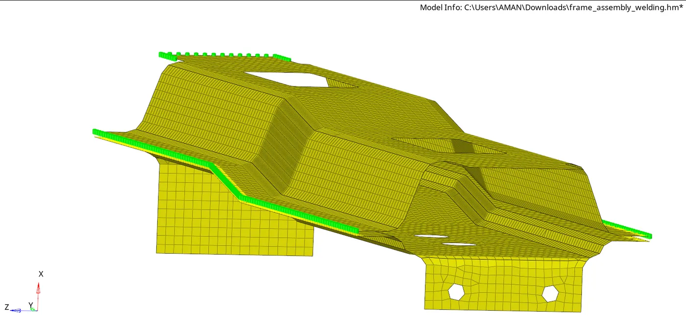
Rest all the component ieft Join them with suitable connectors
- For the rest of all components, connecting them with suitable connectors.
- Reinf_Plate I have connected it with Spot weld with Rigid elements.
- Rear_Trush_1 & Rear Trush 1 are connected using spring element.
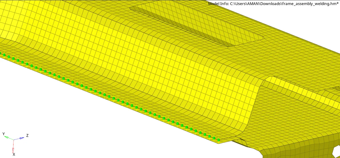
Right Rail 1& Right Rail 2:- Spot-weld with Rigid Elements
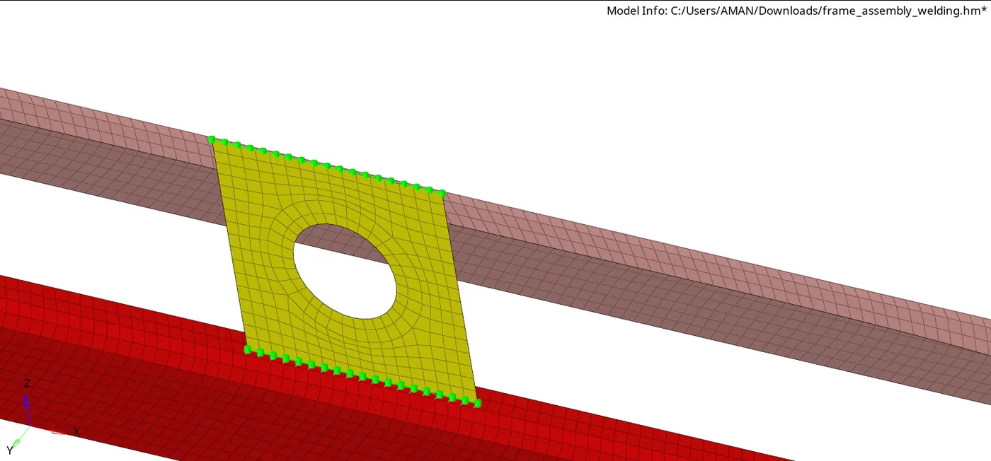
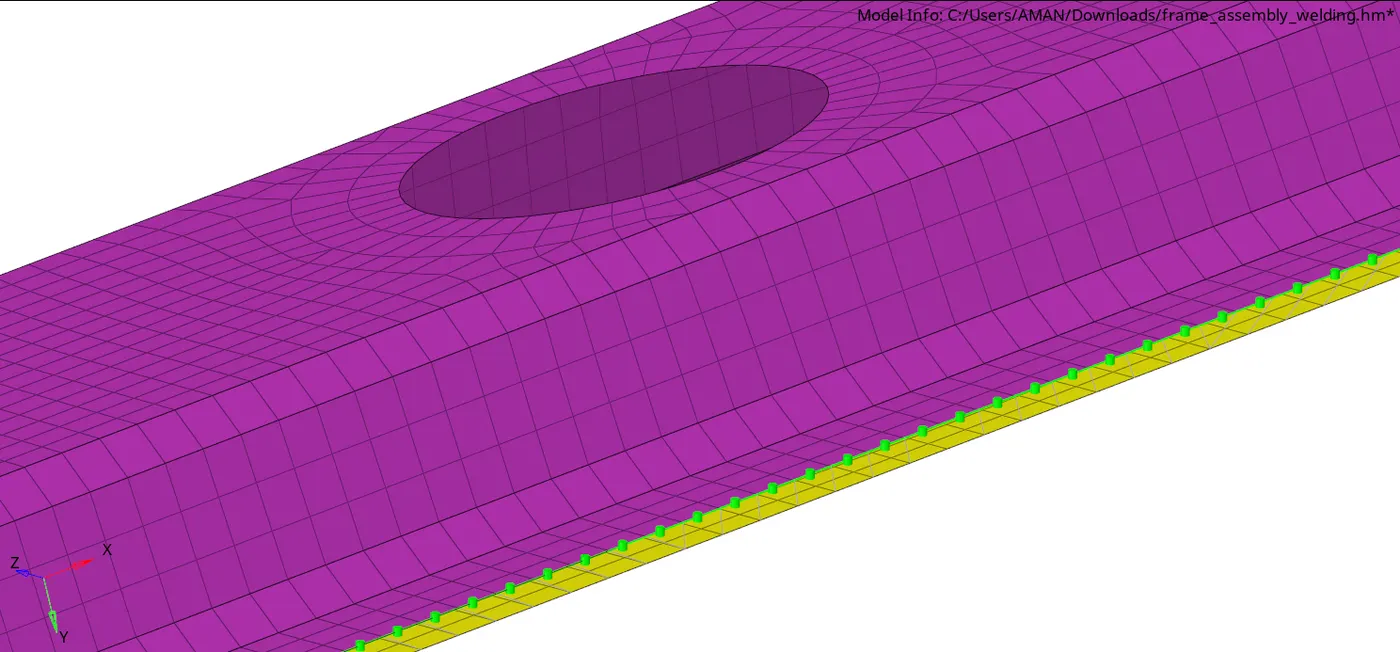
Results
- Learn about the 1-D connectors, their use & importance
- Learn how to implement connectors like spot weld, seam welds, adhesives, bolts, and masses.
- Learn the difference between all the connectors.
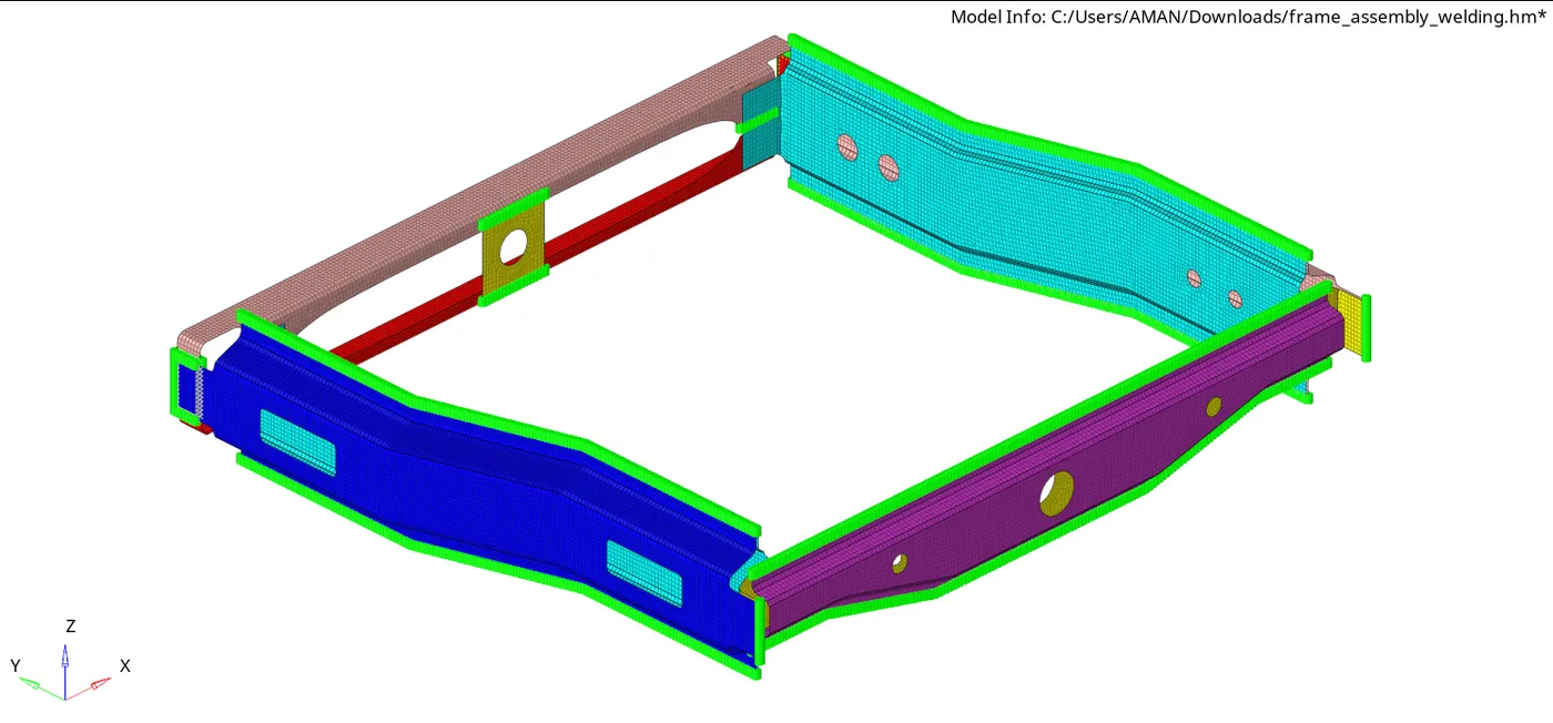
Final model image