Week 8-3D Tetra Meshing Challenge
(1)
Object: - Creating the 3D Tetra mesh for these components Housing and Chassis according to the parameters. In this challenge, we are following the below parameters.
Elements sizes. Min - 3mm, Target - 5mm & 6mm, Max - 7mm.
Tett collapse: 0.15
Procedure:
- Impor the geometry
- Deleting the solid components
- Move the object by using the translate.
- Cleanup the geometry.
- Creating the 2D mesh with given parameters
- Creating the 3D mesh & maintain the tet collapse.
Tet collapse:
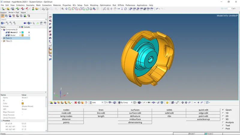
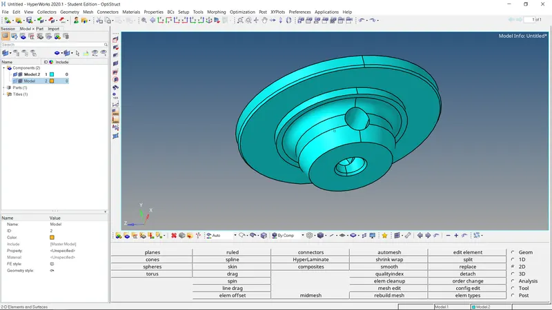
3D mesh quality can check by using the tet collapse. Tet collapse can use to measure the height of the tetra elements. This error when occurs when the tetra elements whose collapse value falls below the value specified, Tetra collapse calculation: At each of the four nodes of the tetra, the distance from the node to the opposite side of the element is divided by the square root of the area of the opposite side. The process starts with the importing the geometry. After importing the geometry we are deleting the solid components for geometry cleanup. The geometry cleanup is carried out by using the quick edit tool and surface edit tool
Defuture
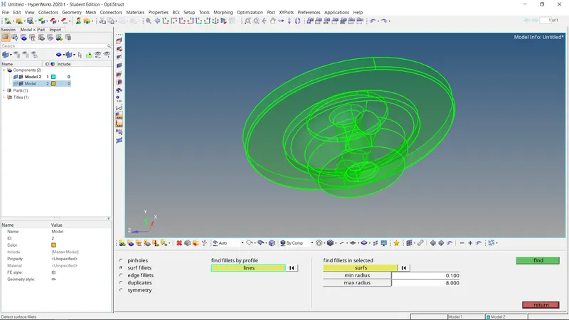
The defeature tool is used to remove the small pinholes and surface fillets which are less than the size of the target length. Translate tool: This tool is used to translate the components at any required directions with reference to the base point.
- Importing the geometry:
Import solver disk - import model - downloads file. This tool is used to import the model, import solver disk consists of the five different tools like import solver disk, import model, import geometry, import connectors & import BOM. In this, all the tools import solver disk is suitable for importing all types of models. Generally, we are using the HM file, STEP file & IGHS file
Deleting the solid components
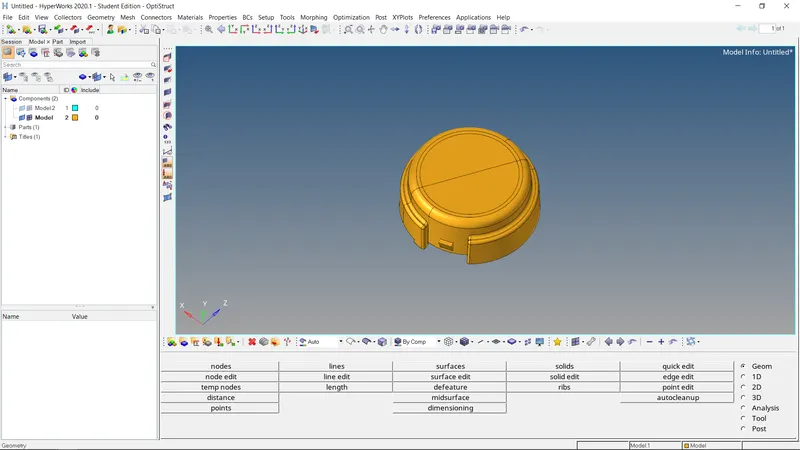
After importing the geometry we are starts working on the geometry. We are deleting the solid components because of the 2D element we can not create on the solid component. By using tool delete tool in that solids using we delete the solid components. The below image shows after deleting the solid model.
Move the object by using the translate. The given model is intersecting one surface to another surface while creating the 3D mesh it creates the difficulty. Therefore we are moving the model by using the tool translate. This tool is used to translate the components at any required directions with reference to the base point.
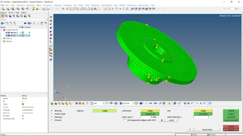
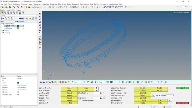
Creating the 2D mesh with given parameters. 2D - Automesh After cleanup the geometry we work on the meshing by using the auto mesh tool in that we are using the size and bias subpanel. Use the Size and Bias subpanel to perform size and bias meshing, a flexible and powerful meshing method. A minimum of inputs are required for the element criteria settings. Size and Bias meshing works interactively or automatically. In interactive mode, manual control is presented via the Secondary Automesh panel during the mesh generation stage. Interactive neshing allows you to control mesh size and element type, and to set different mesh generation algorithms and test element quality on a surface-by-surface basis. The resulting modified mesh can be updated at any time, giving immediate feedback as to the effectiveness of the change. When meshing in the automatic mode, the mesh will be generated using only the settings, criteria and options set in the Automesh panel After creating the 2D mesh as shown in the figure.
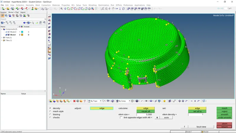
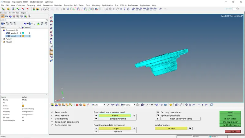
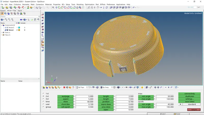
- Creating the 3D mesh & maintain the tet collapse. 3D- Tetramesh A 3D mesh is the structural build of a 3D model consisting of polygons, 3D meshes use reference points in X. Y and Z axes to define shapes with height. width and depth. The 3D mesh can be created by two different methods one is using the tetra mesh another is utility option. A region is considered enclosed if it is entirely bounded by a shell mesh (tria and/or quad elements). Other element configurations generated in this panel are hexahedral, wedge, and pyramids. After creating the 3D mesh as shown in the below images.
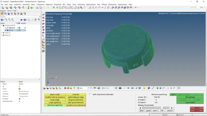
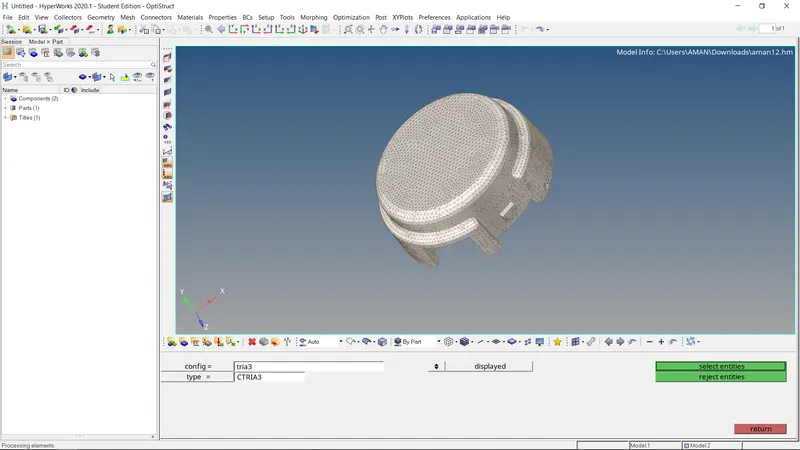
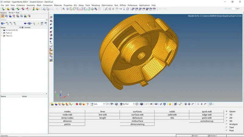
final model.
(2)
Objective : TetraMesh Generation Method: Quick Tetra Mesh/ Volume Tetra Mesh
For Crankhousing mod el the procedure is given below:
1. Go to Import solver deck>>Import geometry>>File type: Model>>select the file»Import. Go to delete>solids>>displayed>>delete
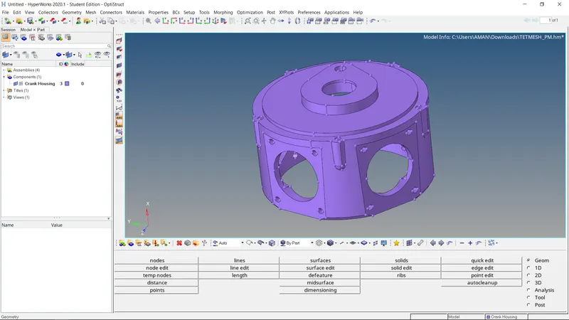
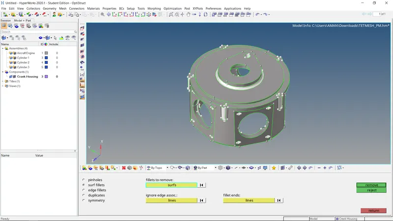
Change the geometry colour mode to "By Topo" to clearly analyse the gemetry. Now go to Geom>»defeature»surf filets»Fillet range: 0.1mm to 8mm>>select surface>find>>remove. This would remove all the fillets in the geomtry. (autocleanup can also be used)
Manually check for errors over the geometry and fix the erros using defeature option or manually remove the fillets by picking the surface individually. Also, use toggle edge option to fix the surfaces near holes. The final cleaned up geometry is shown in the figures below.
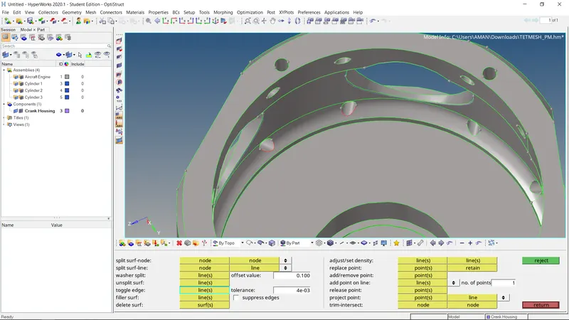
Go to 2D>>sizing and bias>>elem size: 6mm>>elem type: trias>>surfs>>select displayed>»mesh. This would create 2D mesh over the surface as shown in the figure below
Go to 2D>quality criteria>>check for element length failure>>save failed. Go to 2D>>rebuild mesh>»elems>>retrieve»enter the given criteria>>rebuild.
Go to 2D>>elem cleanup>>elems>>retrieve>edit criteria (enter the given criteria)>>cleanup. This step to be done if the erros are not fixed even after rebuilding the mesh. The mesh is cleaned achieved. This is shown in the figure.
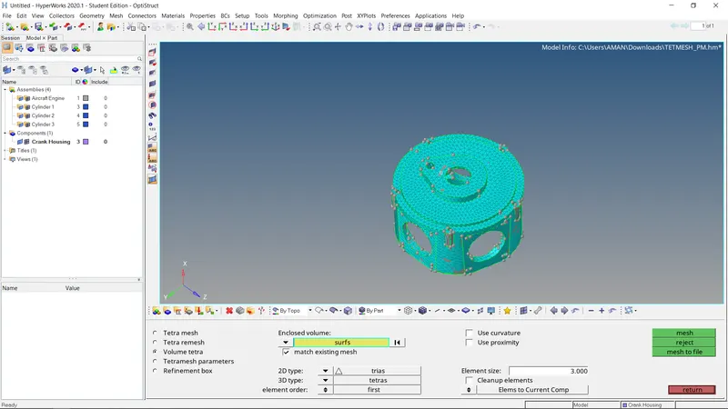
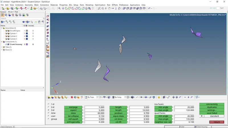
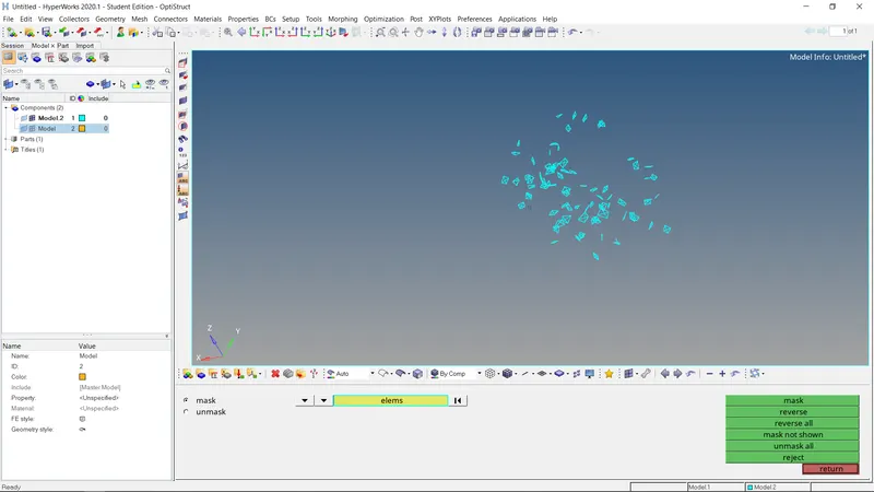
- Go to 30stetramesh Tetramesh parameters>tet collapse: 0.15»Tetra mesh>>elems>displayed>>mesh. 3D tetramesh is created. This is checked by using mask option in the the figure below.
- Go to Toob»check elemns>>3D>»tet collapse: O.15>>check if all the elements pass the criteria. If not manually fix the error by saving the failed elements and retrieving them after masking the other elements.
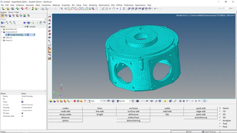
- The final meshed model
(3)
Objective : Create a 3D Tetramesh with the following quality criteria.
Some paremeter we are follow
Target Element size: 4 Units.
Tet Collapse: 0.15
Procedure :
- Impor the geometry
- Deleting the solid components
- Move the object by using the translate.
- Cleanup the geometry.
- Creating the 2D mesh with given parameters
- Creating the 3D mesh & maintain the tet collapse.
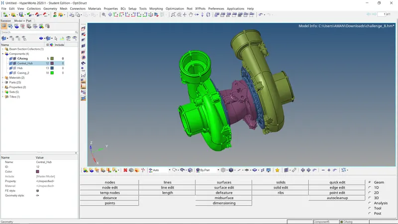
Where we are go on by topo mode and deleted the soild part.
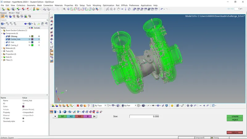
Delete the all entity we are work on casine 1 surface .
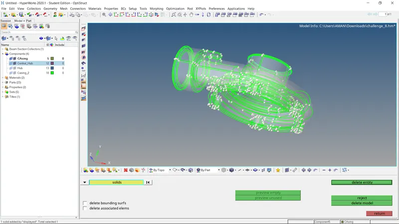
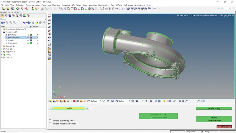
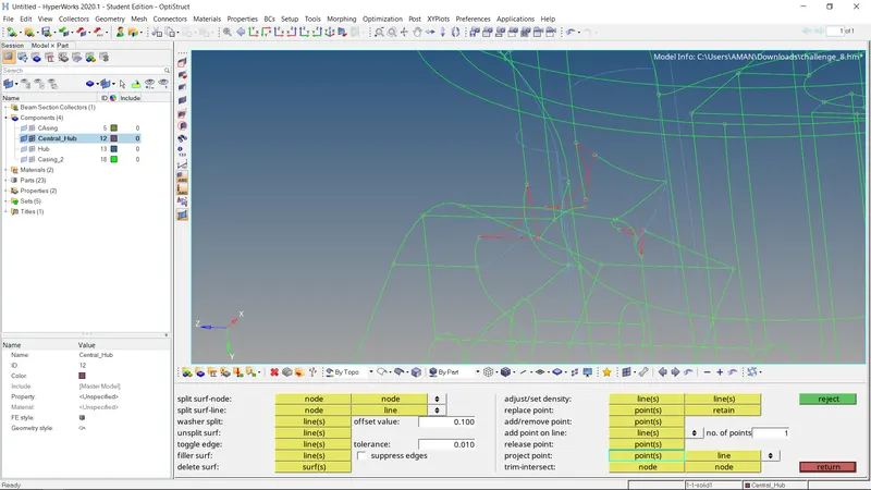
them manually use the defeature for surface fillets .
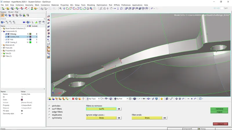
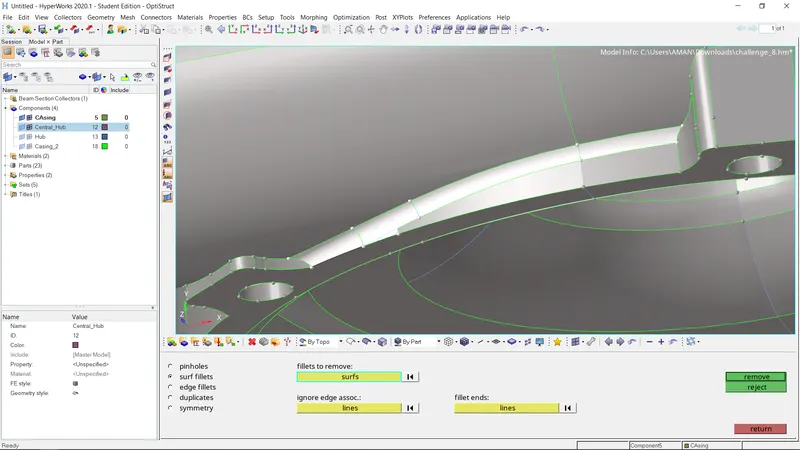
after apply 3d tetramesh < tetramesh parameter (where give tet collapse =0.15 , element size =4 ) < volume tetramesh.
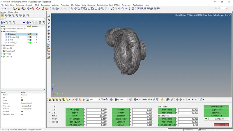
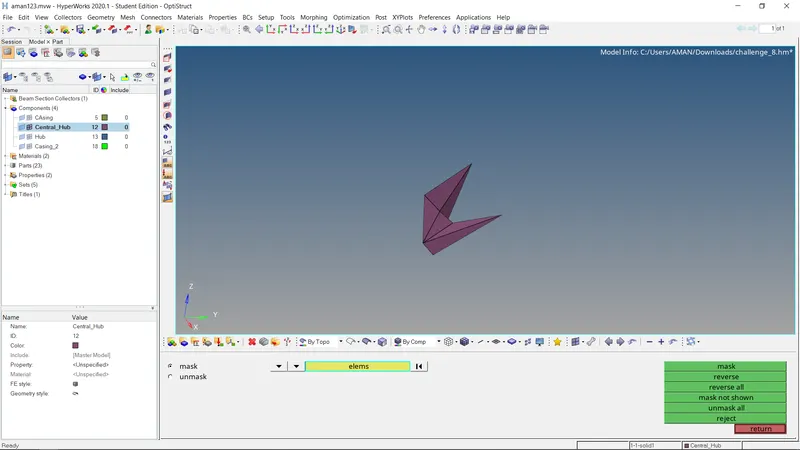
then check the quality where check the tet collapse < save fali
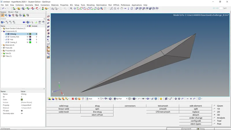
similarly we are done with this casing 2 model.
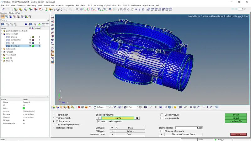
then work on other component central hud.
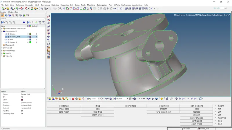
them manually use the defeature for surface fillets .
then check the quality where check the tet collapse < save fali
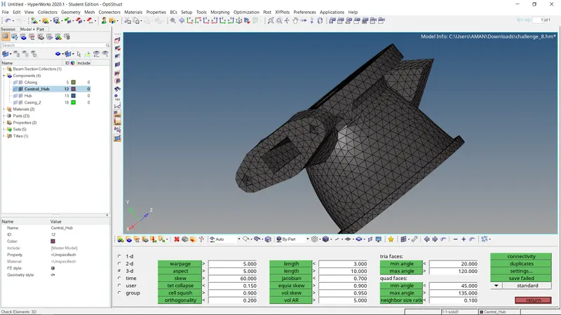
after apply 3d tetramesh < tetramesh parameter (where give tet collapse =0.15 , element size =4 ) < volume tetramesh.
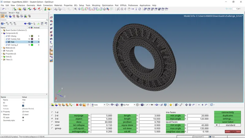
where reflect the one hub to other hub with select base.
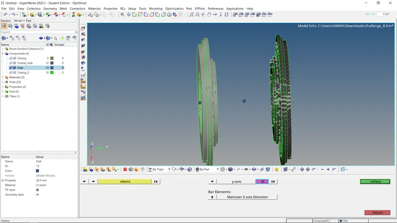
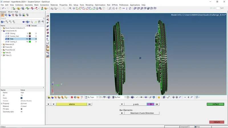
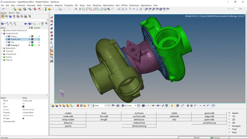
final model