Week 6 - Creating connection for Rear door
Aim: To Deploy Connections for a Front Door by using different PIDS
Principle:
NASTRAN is a finite element analysis(FEA) program that was originally developed for NASA in the late 1960s under United States government funding for the aerospace industry.
The NASTRAN program has evolved over many versions. Each new version contains enhancements in analysis capability and numerical performance. Today, NASTRAN is widely used throughout the world in the aerospace, automotive, and maritime industries. It has been claimed that NASTRAN is the industry standard for basic types of analysis for aerospace structures, e.g. linear, elastic, static, and dynamic analyses.
NASTRAN was designed from the beginning to consist of several modules. A module is a collection of FORTRAN subroutines designed to perform a specific task—processing model geometry, assembling matrices, applying constraints, solving matrix problems, calculating output quantities, conversing with the database, printing the solution, and so on. The modules are controlled by an internal language called the Direct Matrix Abstraction Program (DMAP)
Connections are done on the model to get accurate data during the stimulation. Since the components are meshed separately and then assembles into a system. It is important to do necessary connections so that system behaves correctly during a simulation
Procedure :
The Model is Loaded into ANSA software
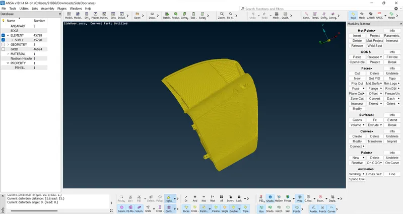
Since all the parts have been assigned to a single PID. It's necessary to assign different PIDS to different parts before a connection can be done
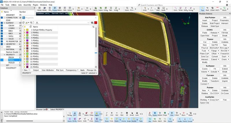
(Different PIDS are assigned to different Parts)
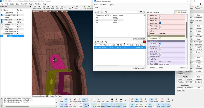
A COG is created since it has many parts. The COG is then converted to Bolt and a connection is made by clicking the bolt and assigning the PIDs
in the connection manager. The connection is made as shown in the above fig
For the Door, the hinges connection is made for the top 2 holes and bottom 2 holes, and a connection is made together by using the two node option in RBE2. Since the door hinges allow the door to move horizontally. The degree of freedom is set to 12345 where the door is allowed to move along the Z axis
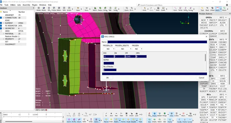
The Door handle Connection is made for both the Holes where the handle is supposed to be assembled. Both connections are then connected using many nodes option RBE2>
Since the handle has a mass. The weight has to be assigned to the connection. It can be done by using the CONMI option.
Note: The weight has to be assigned in terms of Tonnes
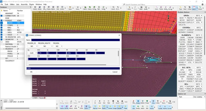
For the Spot weld connections, a COG is created on the part to be Spotwelded then it is converted to Spotweld line using the convert option
After the spot weld line is created Connection can be made using the connection manager
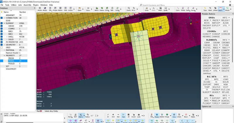
Since the glass is the movable part of the door. It has to be fixed for NVH calculations.
For this Cbush connections are done both for the movable glass and fixed glass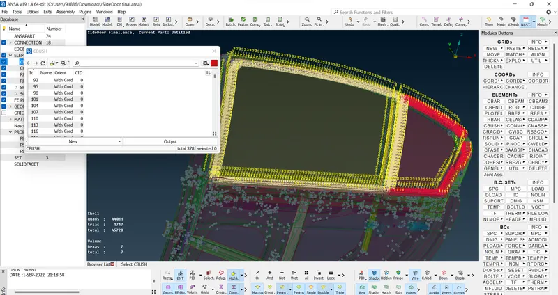
All the Holes connection are made using the RBE2 option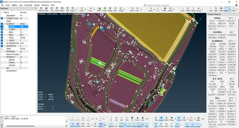
Learning Outcomes:
Learned why connections are necessary for simulation
Learned various types of connections and where to use them in the given model
Learned real-life concepts about the car parts
Conclusion:
Suitable connections are made to the side door by rigid elements, Spot weld, and Cbush connections.
.