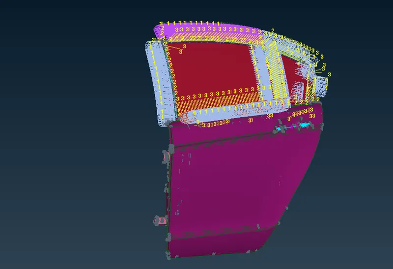
Week 6 - Creating connection for Rear door
Aim: To create connections in the given FE model of rear door assembly.
Procedure:
1. All the components in the assembly are segregated into different PIDs to understand different components better.
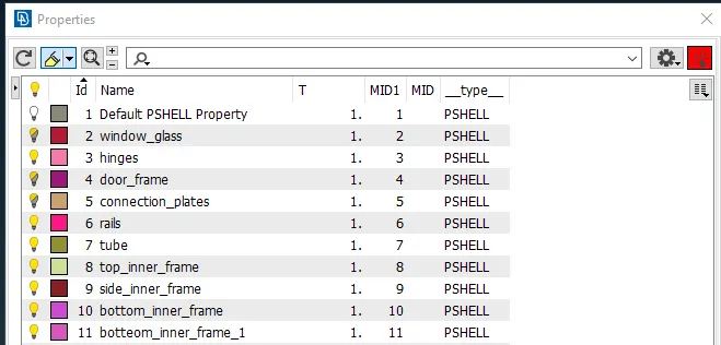
2. Creating connections for the window glasses.
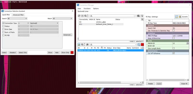
a. PBUSH elements were used to connect window glasses to the rails to simulate the damping effect of the weather seal. Curve was created on the window glass perimeter using Feat2curve option which was then offseted to either sides by 10mm and converted to Seam Line. On the sides other than at the bottom curves were offseted to only one side. In the connection manager following data was given and the connection was realized.
FE Rep Type : RBE3-CBUSH-RBE3
Search Distance : 30
P1 and P2 were selected.
3. Connecting the rails
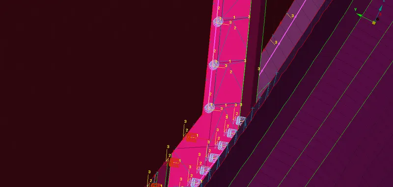
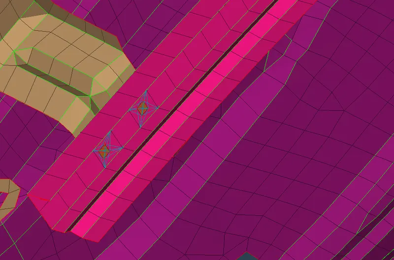
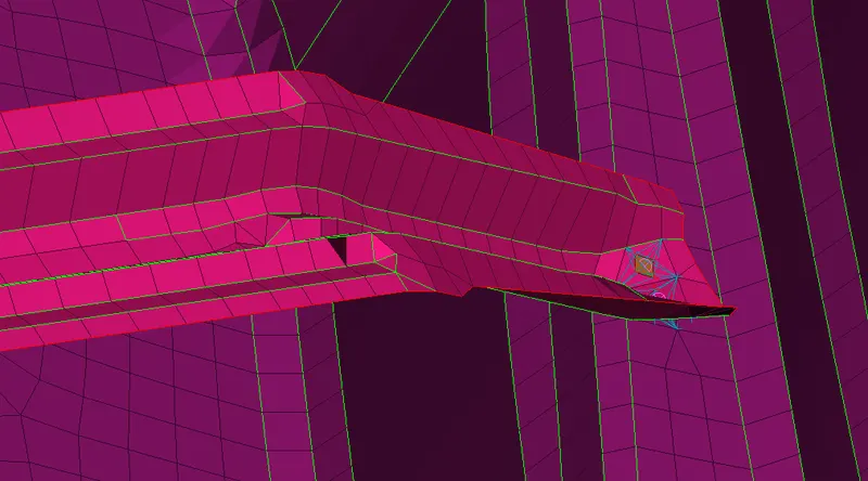
Spot weld was used to connect the rails either to the connector plates wherever available as in first image or to the main door frame as in the second image.
A 3D point was created using on-COG option which was then converted to a spot-weld point. In the connection manager, the following data was given and the connection was realized.
FE Rep Type : RBE3-HEXA-RBE3
Search Distance : 20
P1 and P2 were selected.
4. Connecting the connector plates to the main door frame.
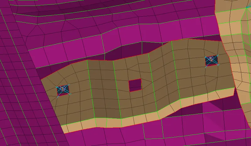
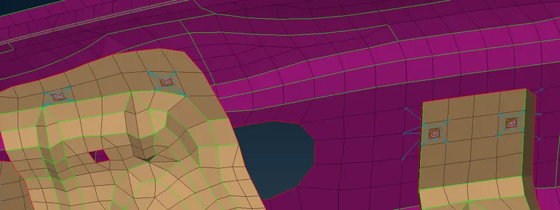
Wherever matching holes were found on the components, bolt connection were made (fig.1) and spot welds were used on other locations (fig.2).
Creating bolt connection:
A 3D point was created using on-COG option which was then converted to Bolt type.
FE Rep Type was selected as BOLT. Search distance was set to 20. P1 and P2 were selected. With all the DOFs constrained, the bolt connection was realized.
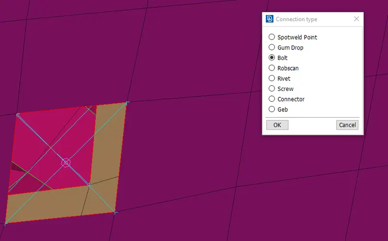
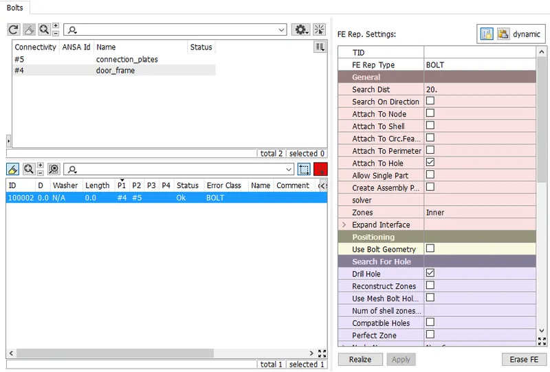
- Connecting the rods to the connector plates.
Seam weld connection was tried at one location (fig.1) but since it altered the mesh to a large extent on other location spot weld connection was employed (fig.2).
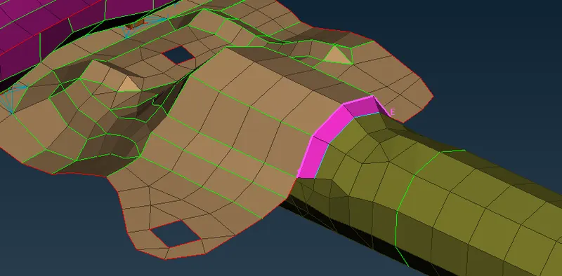
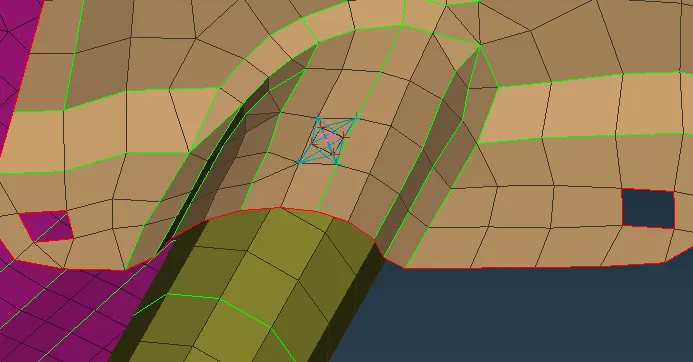
- Creating seam weld connection
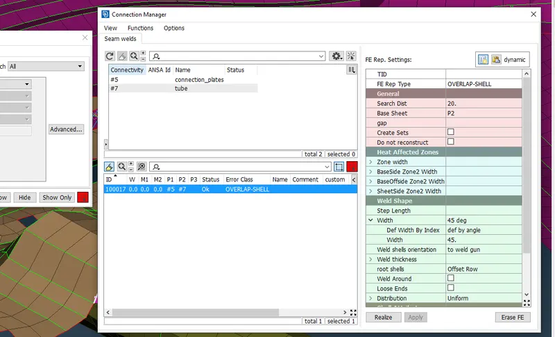
A curve was created using Feat2curve option which was then converted to a spot line. In the connection manager, the spot line is selected. After selecting the corresponding PIDs P1 and P2, overlap-shell is selected as the FE rep Type since the faces to be joined are parallel to each other as can be seen from the above image. Search distance is provided and the rod was selected as the base sheet. Width angle of 45 deg was given and the connection was realized.
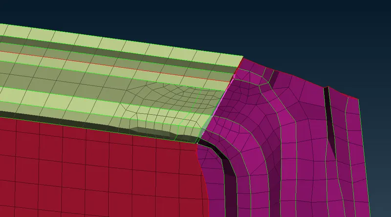
Seam weld was also used to connect the door frames with each other as shown in the below fig.
- Connecting the hinges.
The hinges were connected to the door frame via bolt connection with all the degrees of freedom constrained, while the hinge to hinge connection was realized with bolt connection with rotation about the Z-Axis not constrained.
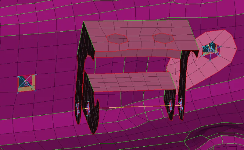
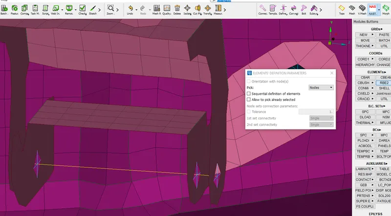
Bolt connection was made following the same procedure as mentioned already in the report. Then (Elements > RBE2 > 2 nodes) was used to define the bolt body with the 6th DOF unconstrained.
7. Representing the door handle.
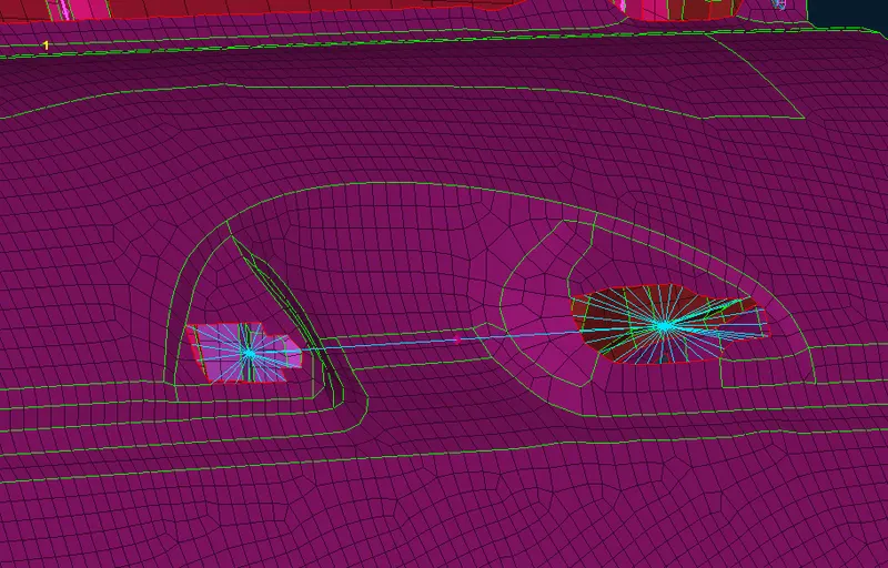
RBE2 elements were created using many nodes option. Then a rigid RBE2 element was created connecting these two elements and a mass of 100gms was added to it using (elements > CONMi).
Conclusion:
The required connections were made for the rear door assembly.