Week 3 - 2D meshing for sheet metal
Aim:
To create FE model for the given Hood Assembly after clearing the geometrical errors by extracting the mid-surface, according
to the given quality criteria.
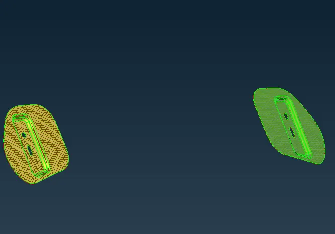
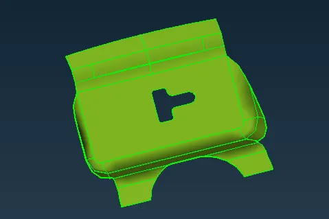
CAD components in the Assembly:
1.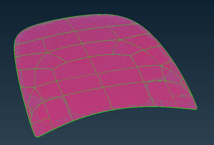 2.
2. 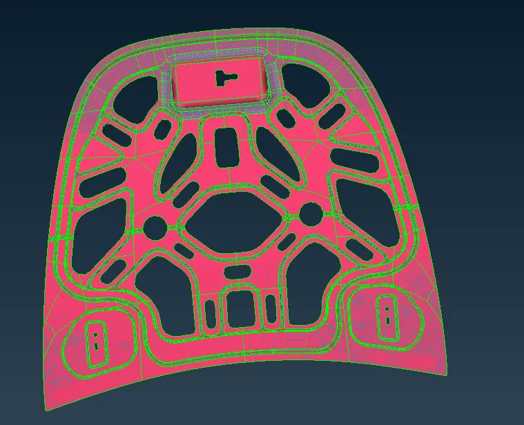 3.
3. 
4.
Quality Criteria:
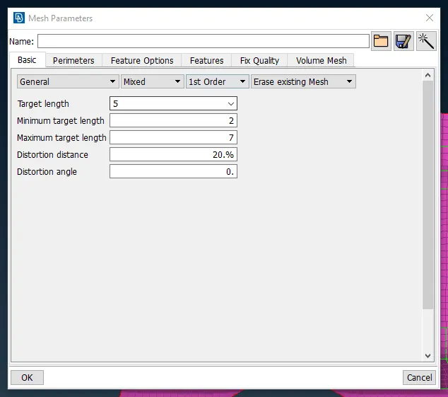
Target/Average length 5 mm
Minimum Length 2 mm
Maximum Length 7 mm
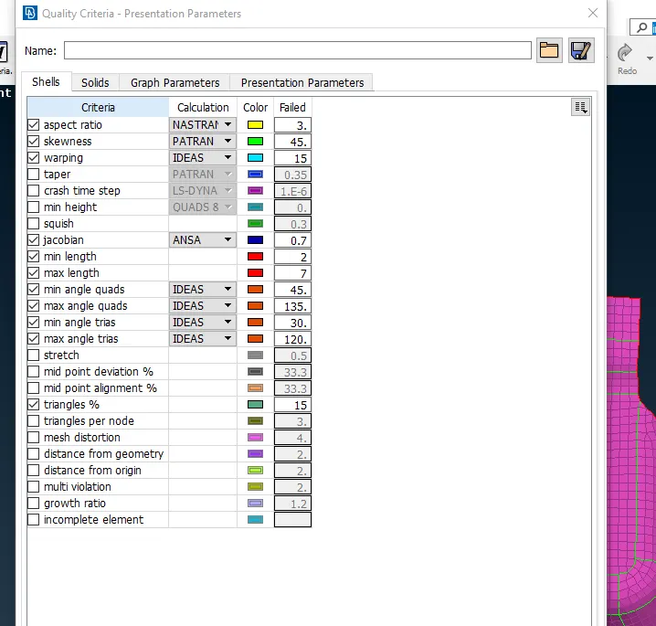
Aspect 3
Warpage 15
Skewness 45
Jacobian 0.7
Minimum Quad Angle 45 degree
Maximum Quad Angle 135 degree
Minimum Tria Angle 30 degree
Maximum Tria Angle 120 degree
Tria Percentage 15
Procedure:
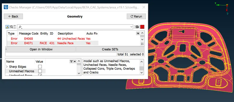
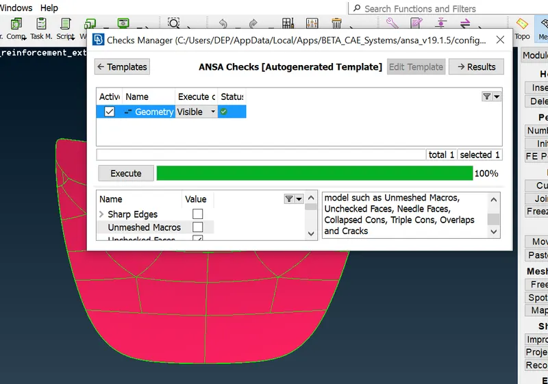
A. Geometry Check - Given CAD has to be checked for any errors- CHECK MANAGER > GEOMETRY
Most of the geometrical errors were fixed by selecting the errors > right mouse click> FIX.
Some errors like undesired triple cons were fixed by releasing the cons first and then stitching it
manually.
B. Component selection:
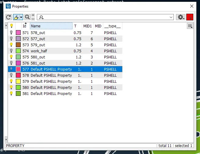
Out of the 5 components present in the assembly each were worked upon individually by opening the PROPERTIES Panel
right-clicking and selecting SHOW ONLY.
C. Checking the Orientation:
TOPO > ORIENT(visible) option was used to get the correct orientation for the cad faces.
D. Extracting the Mid-Surface:
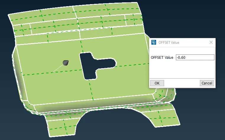
Being sheet metal parts (constant thickness), I went for TOPO > OFFSET option and used FEATURE AREA selection
to select the faces to offset. The selected faces were offsetted by half of the thickness value.
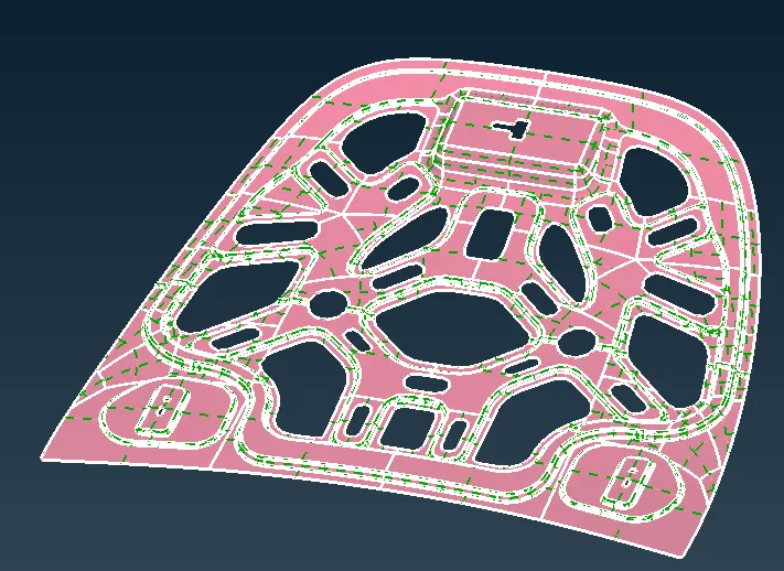 Faces selected using FEATURE AREA selection.
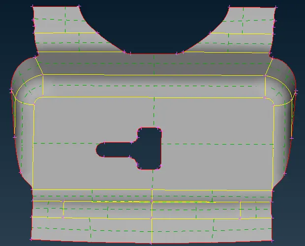 Mid-surface extracted.
E. Mid-Surface check:
TOPO > FACES > TOPO was performed to stitch some single cons. Also, the mid-surface was checked for any errors using
CHECK MANAGER.
F. Assigning PIDs to the mid-surface:
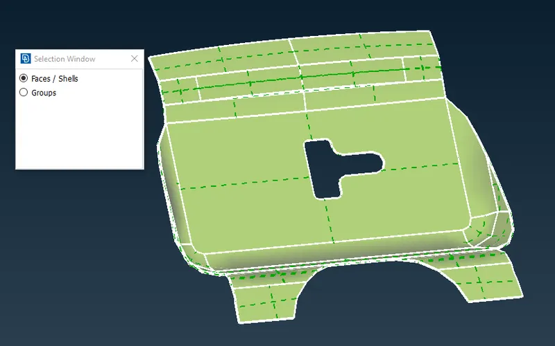
TOPO > FACES > SetPID was used to create new PID for the mid-surface thereby assigning the thickness as well.
G. Handling Symmetric Components:
All the components (1-4) have symmetry in varying levels
Comps 1 & 3 have perfect symmetry.
Comp 2 & 4 have about 90% symmetry.
Symmetry was checked using: TOPO > FACES > Rm.Dbl
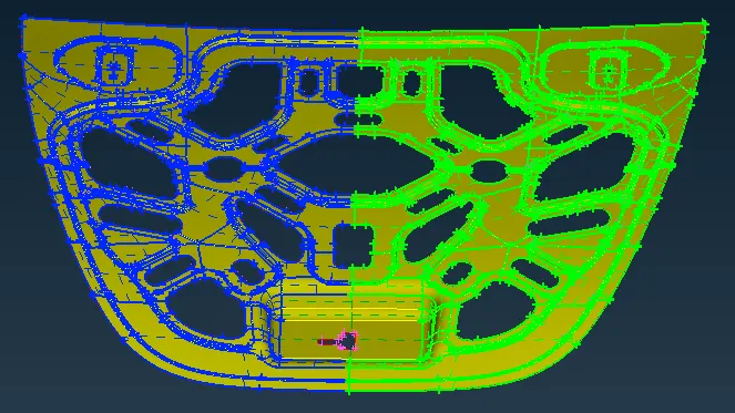
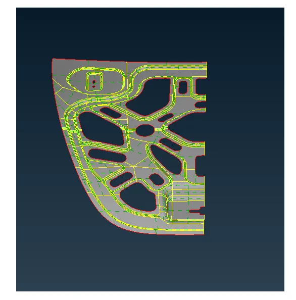 For symmetric components, half of the mid-surface was modelled and reflected.
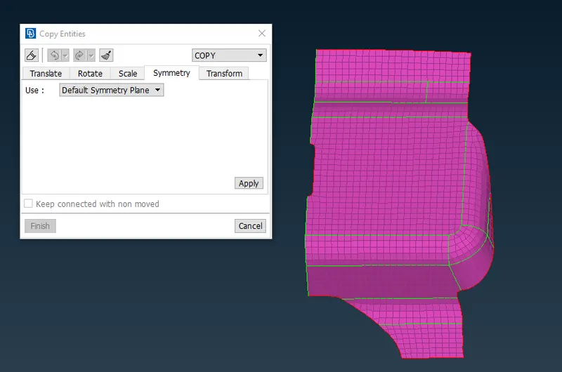 Transform > move > symmetric
H. Setting Mesh Parameters and Quality Criteria:
Mesh Parameters and Quality Criteria from the given data is entered.
I. Assigning Perimeter Length and alignment of holes:
MESH > PERIMETERS > LENGTH option was used to set the perimeters and macros length as 5 mm which is the average
length according to the given data.
MESH > PERIMETERS > SLIDE option was used to move the hot points along the perimeter of the holes to align the sides
parallel to their nearest edge.
MESH > HOTPOINTS > Mark/Un option was used to fix the hotpoints around the holes.
J. Getting the mid-surface ready for meshing:
1.
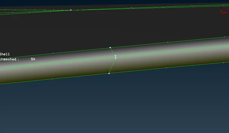 Fillet region which was failing for minimum length
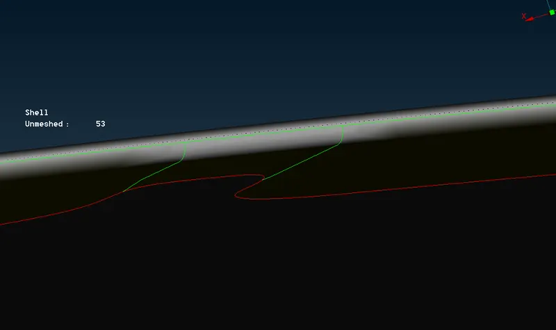 The peak of the fillet was captured.
2.
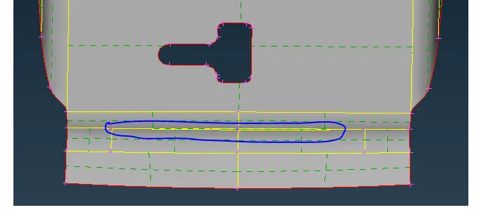 Many cons in the components were found to be too close that
elements would be failing for minimum length. In such cases, the prominent con was kept and the other was defeatured using
mesh > macros > join.
K. Generating Mesh:
Mesh > Mesh Generation > Best option was used to create mesh. The mid-surface was divided into smaller manageable portions using
Mesh > Macros > Cut to get a proper mesh flow.
Hidden view was turned on to spot the failing elements which were corrected by using various tools like reconstruct, smooth move, split,
swap, paste etc.
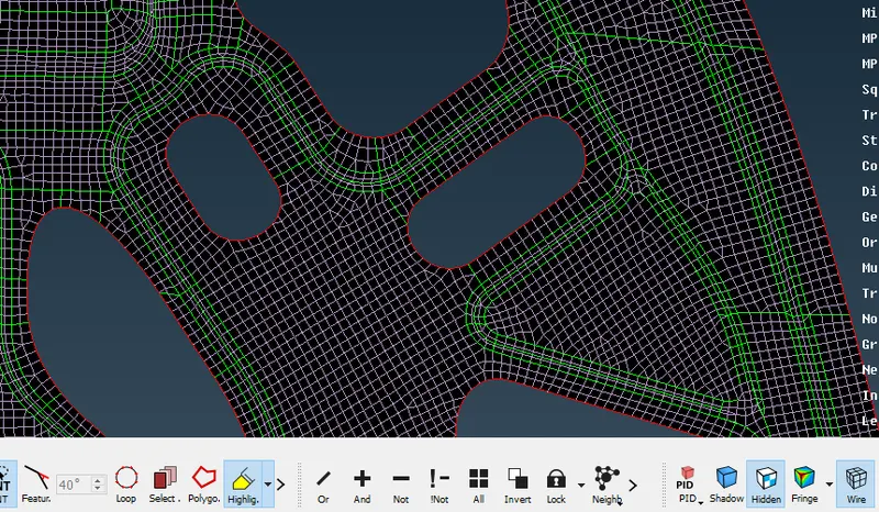
L. Quality Check
Elements were adjusted to follow the given quality criteria.
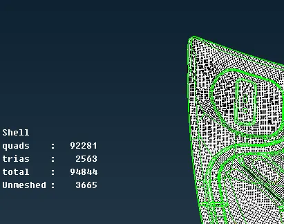
Tria percentage of the components was found to be under the allowable limit of 15%.
For the complete assembly tria percentage was found out to be 2.7%.
M.Conclusion
Mid-surface was extracted and mesh was created for the sheet metal components.
The offset option was used to extract the mid since all the components were sheet metal parts.
An attempt was made to capture all the feature lines except when it led to quality issues.