Week - 4 - 2D meshing for Plastic components
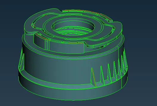
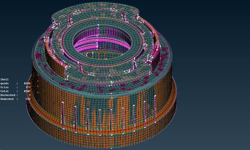
Aim: To create FE model for the given bottle cap model by extracting the mid-surface, according to the given quality criteria.
|
S.No |
Quality Criteria |
Value |
|
1 |
Target/Average length |
1 |
|
2 |
Minimum Length |
0.5 |
|
3 |
Maximum Length |
3 |
|
4 |
Aspect |
3 |
|
5 |
Warpage |
15 |
|
6 |
Skewness |
45 |
|
7 |
Jacobian |
0.7 |
|
8 |
Minimum Quad Angle |
45 |
|
9 |
Maximum Quad Angle |
135 |
|
10 |
Minimum Tria Angle |
30 |
|
11 |
Maximum Tria Angle |
120 |
|
10 |
Tria Percentage |
15 |
Procedure
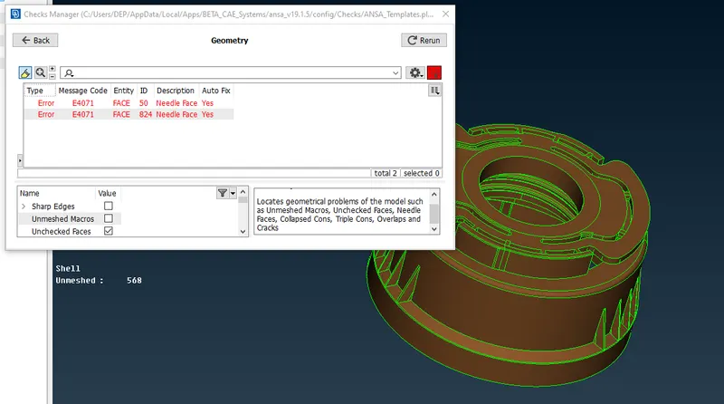
A. Geometry Check: Given CAD has to be checked for any errors- CHECK MANAGER > GEOMETRY
For the given model, both the CAD errors were fixed by selecting the errors > right mouse click> FIX.
B. Checking the Orientation:
TOPO > ORIENT(visible) option was used to get the correct orientation for the cad faces.
C. Extracting the Mid-Surface:
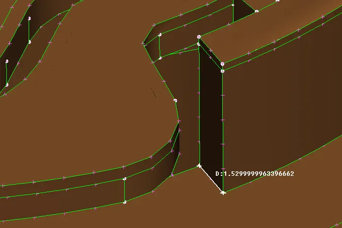
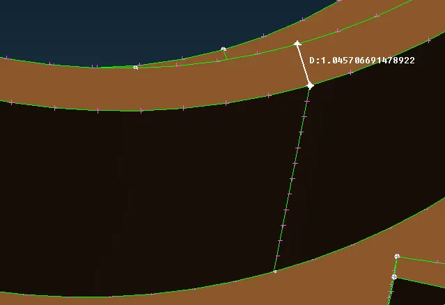
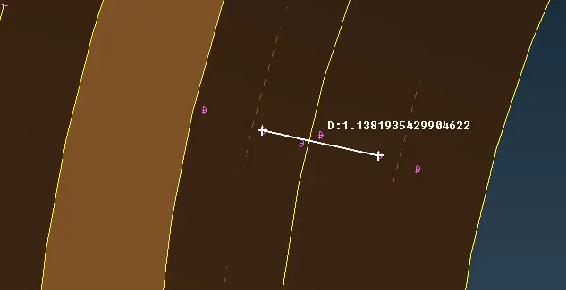
The thickness of individual cad surface pairs was found using the measure option either by checking on the hotpoints on the surface edges or/and
creating weldspots on one surface, projecting it to the surface pair, and measuring the distance between them.
I proceeded with Faces > Offset > Faces for the mid-surface creation in constant thickness areas.
Faces > Middle option was used where the thickness was varying.
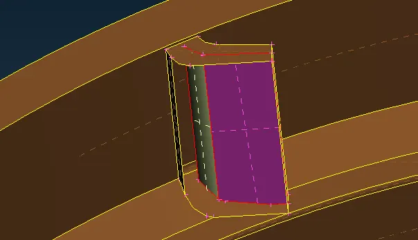
C.1: Transform > Copy > Rotate option was used to reuse the features that were repeated in a circular fashion.
Eg: 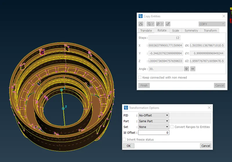
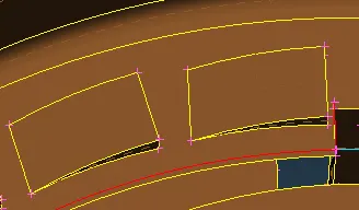
C.2: In locations where offset and middle options did not work, curves were created using Curves > Middle, and mid-surface was created
using Faces > New.
Eg : 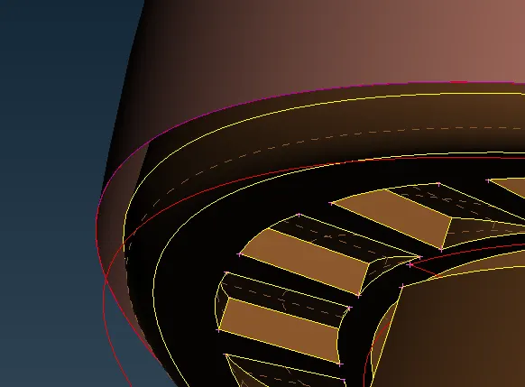
C.3 : Capturing mid-surface for the threads
A curve was created on the end face of the thread which was then projected to the base mid-surface. A new surface was created by selecting the
curves and the cons created by the curve projection.
Eg: 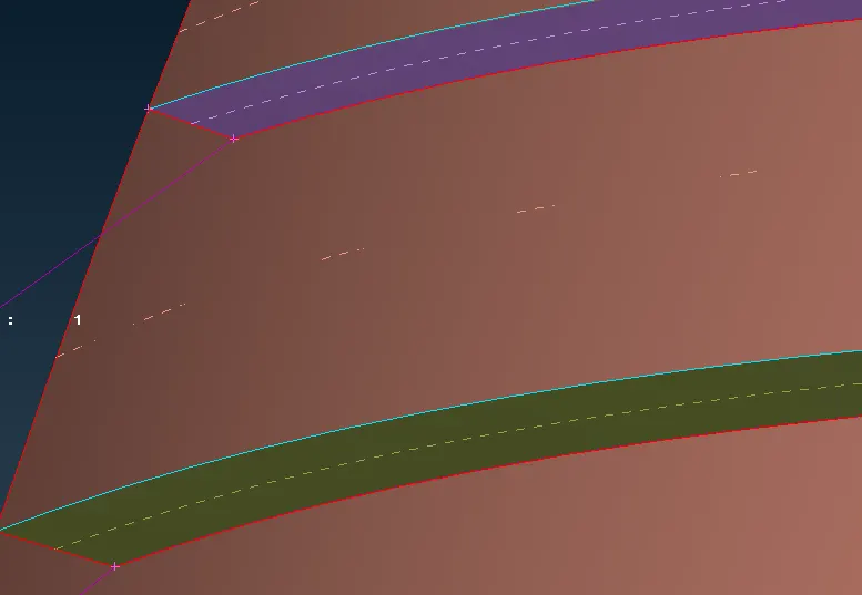
Options like Topo, Plane Cut, Intersect, Extend, etc were extensively used to extract the mid-surface for the bottle cap.
D. Setting Mesh Parameters and Quality Criteria:
Mesh Parameters and Quality Criteria from the given data are entered.
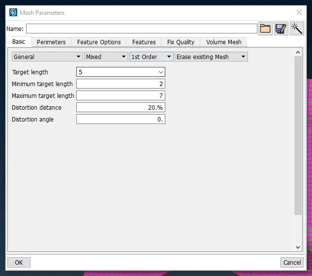
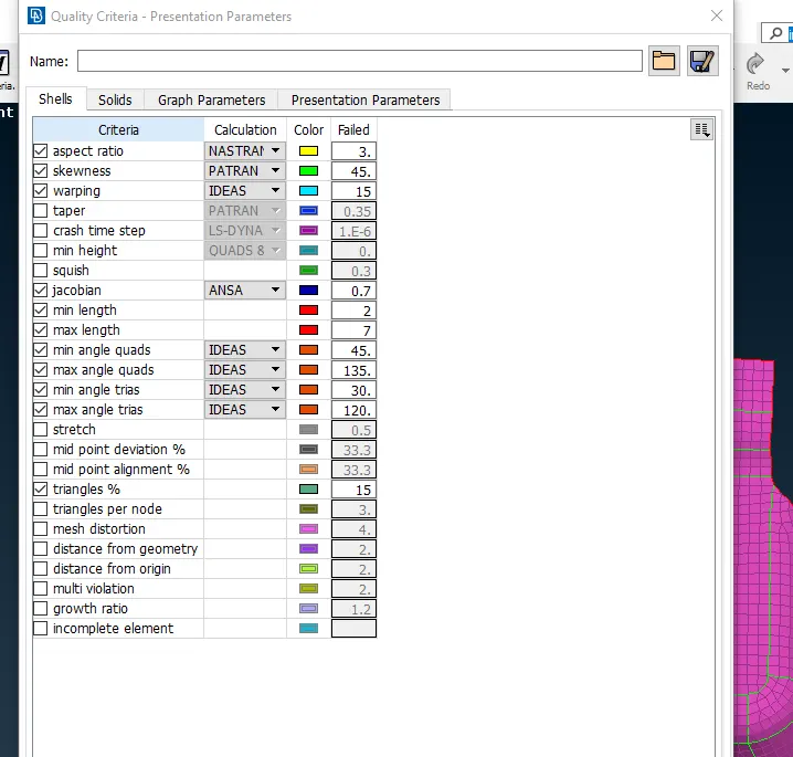
E. Assigning Perimeter Length
MESH > PERIMETERS > LENGTH option was used to set the perimeters and macros length as 1 mm which is the average
length according to the given data.
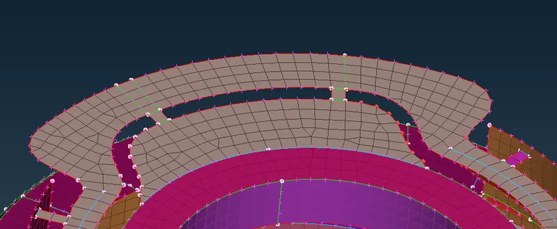
F. Meshing on the Mid-surface
Mesh > Mesh Generation > Best option was used to generate the mesh. The mid-surface was divided into smaller manageable portions using
Mesh > Macros > Cut to get a proper mesh flow.
The hidden view was turned on to spot the failing elements which were corrected by using various tools like reconstruct, smooth move, split,
swap, paste, etc.
G. Quality Check
Elements were adjusted to follow the given quality criteria.
Tria percentage of the components was found to be under the allowable limit of 15%.
For the component, the tria percentage was found to be 2.01%.
H. Assigning Thickness
Macros > Set PID was selected and new shell property was created to assign thickness to the elements. In case of varying thickness in a feature,
the macros were split using either Macros > Cut or Macros > Edge2perimeter.
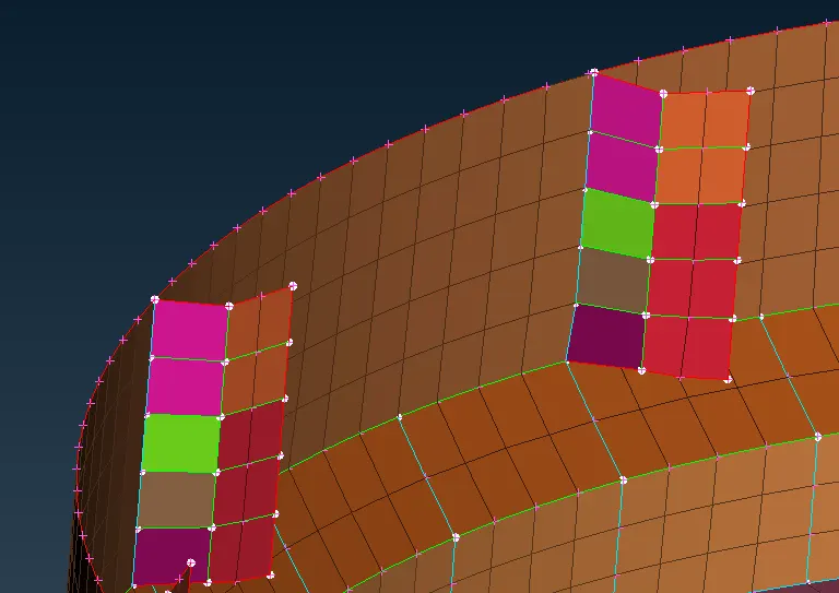
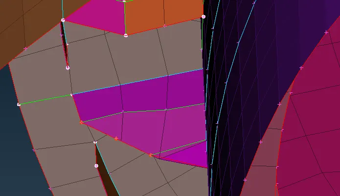
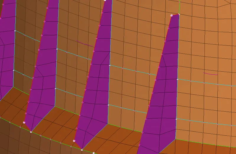
From presentation parameters, 'draw shell as solid' was ticked to check the accuracy of thickness assignment
I.Conclusion
Mid-surface was extracted and mesh was created for the bottle cap.
The offset, middle and other manual methods were employed to extract the mid-surface.
An attempt was made to capture all the feature lines except when it led to quality issues.