Tool Test 1
AIM:
To extract mid-surface for the given two models and create FE model according to the quality criteria given below.
QUALITY CRITERIA:
|
S.No |
Quality Criteria |
Value |
|
1 |
Target/Average length |
4 |
|
2 |
Minimum Length |
2 |
|
3 |
Maximum Length |
6 |
|
4 |
Aspect |
3 |
|
5 |
Warpage |
15 |
|
6 |
Skewness |
45 |
|
7 |
Jacobian |
0.7 |
|
8 |
Minimum Quad Angle |
45 |
|
9 |
Maximum Quad Angle |
135 |
|
10 |
Minimum Tria Angle |
30 |
|
11 |
Maximum Tria Angle |
120 |
|
10 |
Tria Percentage |
15 |
MODELS:
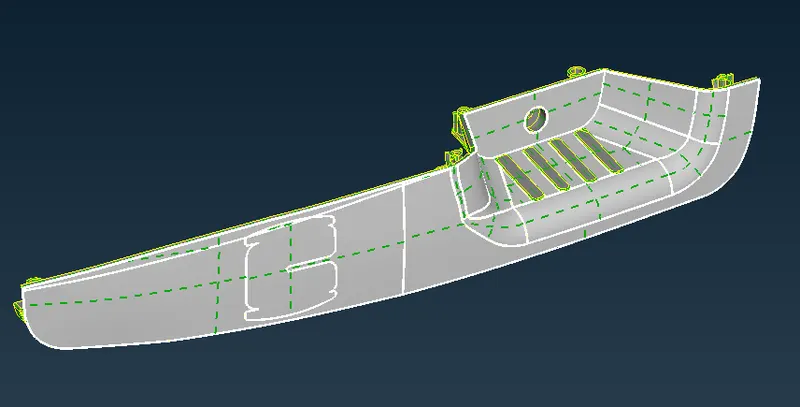
Model 2 Model 1
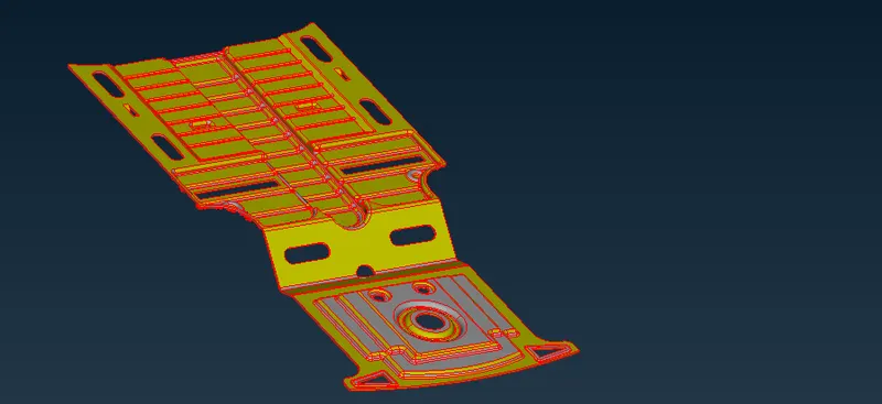
PROCEDURE:
Model 2:
Initial checks:
a. resolution was set in mesh > perimeter > length
b. orientation was corrected in topo > faces > orient
c. topo was done to paste the single cons
d.geometry check was done
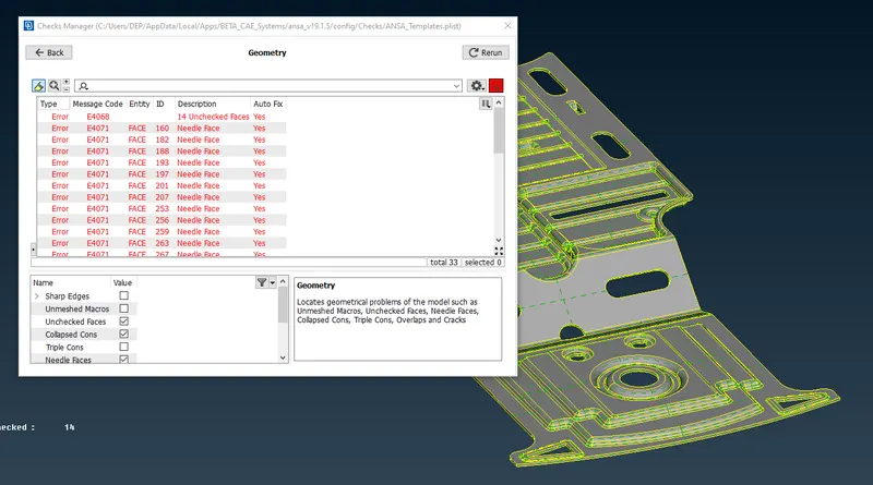 all the errors were corrected by fix option.
Since it is a sheet-metal part, topo > faces > offset option was used to generate mid-surface. The offset value was 1.00 mm.
The symmetry of the model was checked from topo > faces > Rm.Dbl.
It was found that the model is symmetric except for a feature.
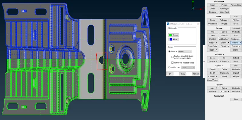
Therefore, mid-surface cleanup and meshing were done on only half of the mid-surface.
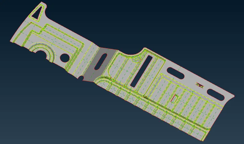
mesh > mesh generation > best option was used to generate the mesh.
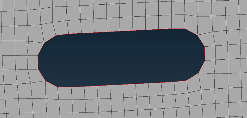
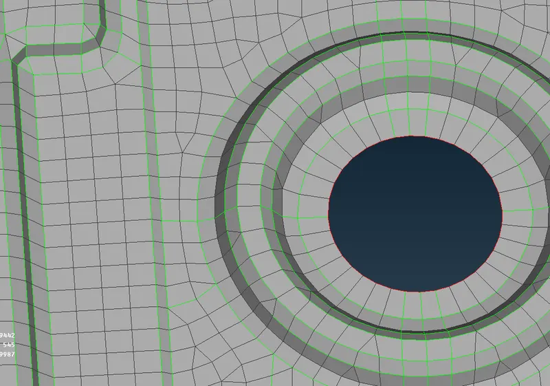
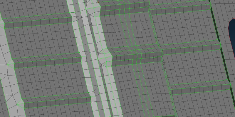
Holes and slots were captured with an even number of elements and peaks of the beads were captured. Trias were kept away from the feature lines and free edges as much as possible.
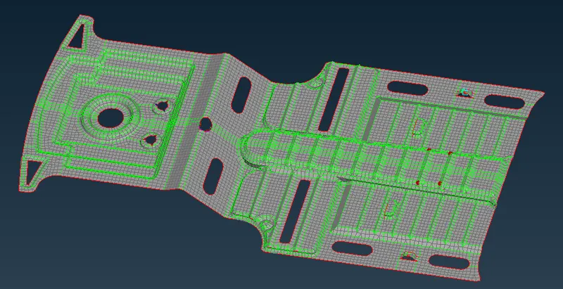
After half of the model was done it was reflected on the default axis to get the full model.
Final output after the symmetry updates :
Model 1:
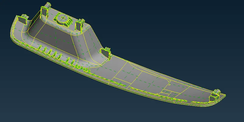
All the initial checks were done as mentioned for model 2.
Since there were no geometrical errors, I moved to mid-surface generation.
The base of the model was having a 3mm thickness throughout. Therefore I used topo > faces > offset to get the mid-surface for the base.
Using feature selection all of the base was selected and offset.
Mid-surface generation:
topo > faces > middle was used for all the ribs.
Features that did not have a constant thickness and when faces > middle did not give a proper result, middle curves were created around the feature, and topo > faces > new option was used to get the mid-surface.
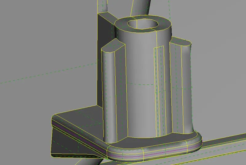
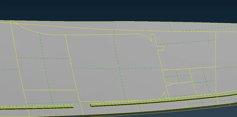
Many feature lines that did not mark any change in surface profiles were neglected.
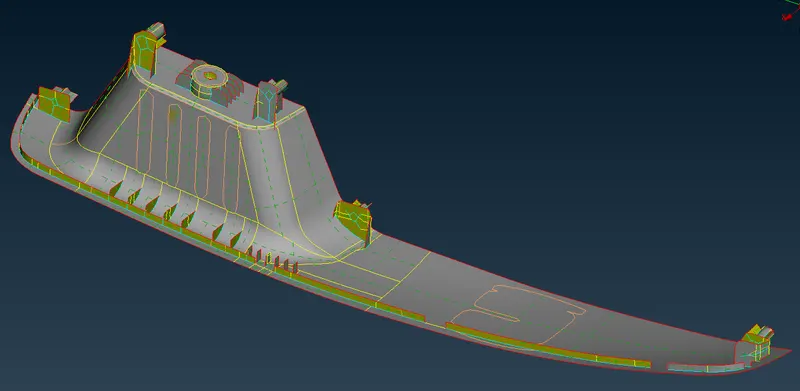
Mid-surface generated is as shown below:
mesh > mesh.generation > best option was used to generate the mesh.
Large macros were split using mesh > macros > cut to get an even mesh flow.
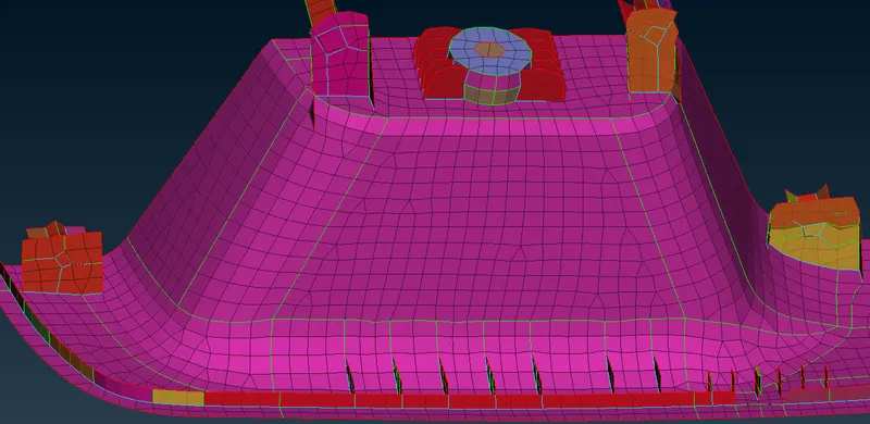
Trias were kept away from the feature lines and free edges as much as possible. Tria in one of the fillet regions could not be avoided as shown in the figure above.
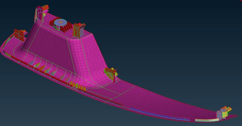
After all the macros were meshed and off elements were brought to zero, step-thickness was set for the model manually using mesh > macros > setpid option.
The final FE model was obtained as shown below.
Time taken :
Sheet-metal part: 5 hrs
Switch panel: 6 hrs