Week 6 - Creating connection for Rear door
Aim :
- The given Rear door FE model, Perform suitable connections between various parts .
- Create and Apply different PIDs for different components.
Procedure :
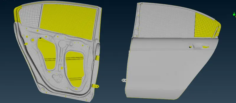
- First we need to import the model as shown. Then the entire model will be separated into different PIDs
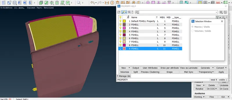
- This process can done by using Set PID > Select Macro / shells and assign the property
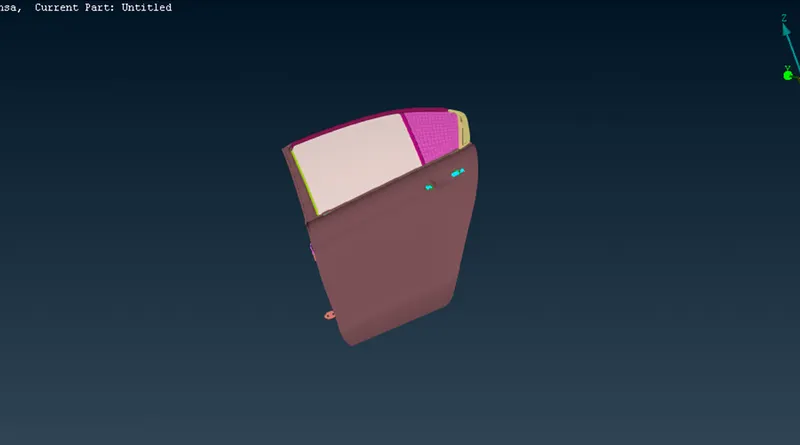
- This process is repeated until PIDs have been assigned for every component in the model.
BOLT CONNECTION
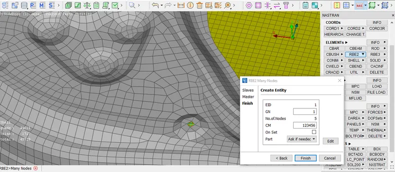
- We can start with RBE2 connections . This option can be done by NASTRAN DECK > ELEMENTS > MANY NODES
- We deploy the 'MANY NODES' option . This is merely done by selecting the two sets of nodes surrounding the holes and letting the alogrithm create a master node and form connections . This also called as cluster node RBE2
- Next we moved two node RBE2 connection . this option specially used in hinge area due to hinge joint requires yaw movement
- And, such will have 5 D.O.F s fixed . Meaning , When defining it during the two nodes RBE process, care must be taken to ensure the value of 'CM'is 12345 to allow the movement
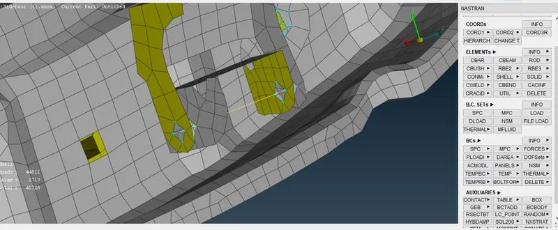
- There is another way to assign bolt connections which becomes especially useful in cases where there are more than 2 layers that requries connecting.
- This will involve using the connection manager . Before that , we need to create a COG point in one of the holes from a layer in the middle
- Using the POINT > ON COG . Then point needs to be converted into a bolt using the convert tool
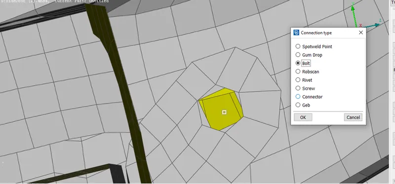
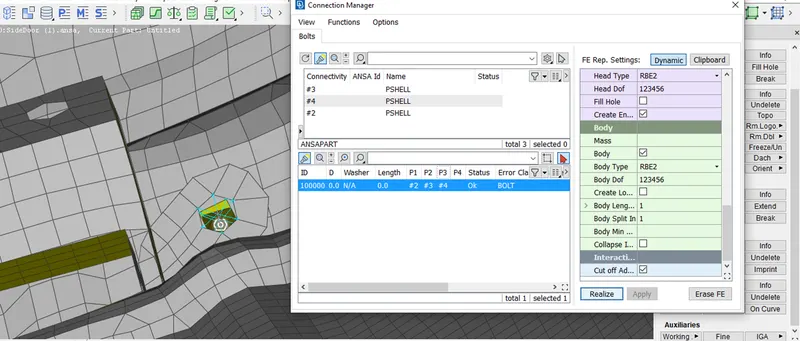
- After converting the point into a bolt , the connection manager is accessed and the bolt point selected
- In connection manager we need to assign the P1,P2 & P3 by selecting the PIDs
- Then FE Rep type needs to be 'BOLT' . The search distance can be assigned according to the distance from the bolt point.
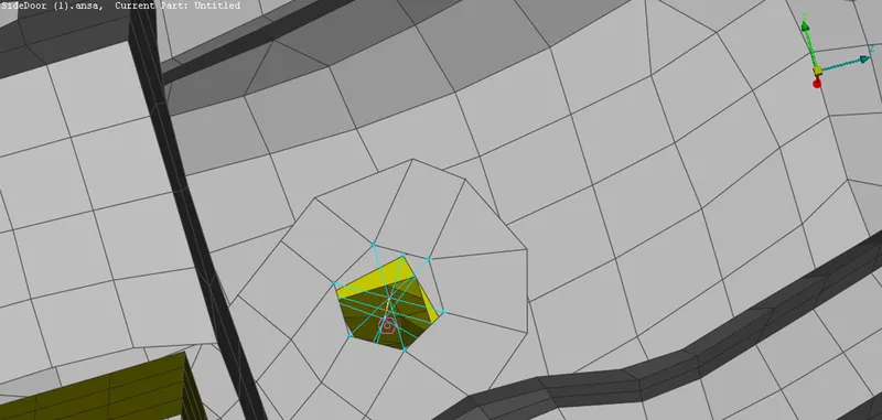
- The Result of this connection as shown.
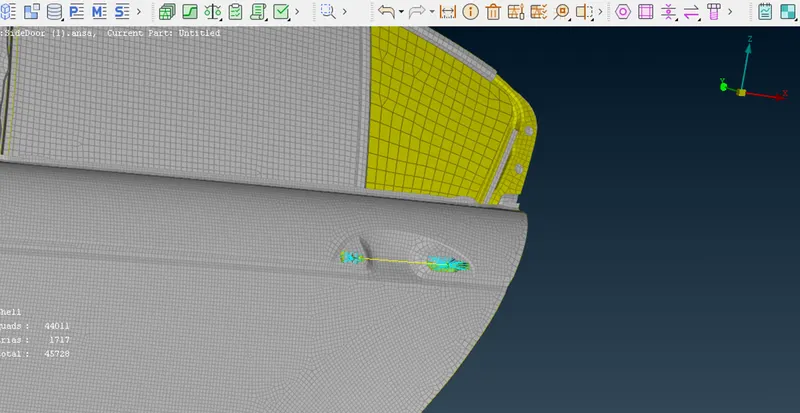
- Now into the door handle , in this region , we need to create a connection that applies a mass . For this , we need to create RBE2 nodes in either handle holes separetly
- Again , using the same tool , the two master nodes for either handle hole is selected and another connection is created , with the alogrithm assigning a new master node at the centre of this connection
- Now , we make use the Con Mass tool accessible through ELEMENT > CONMI > NODES .
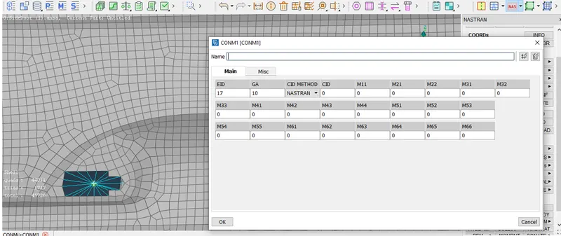
- Then the priviously mentioned master node is selected . This is where the mass of the handle will be concentrated . After proceeding let us assign the mass.
WELD CONNECTION
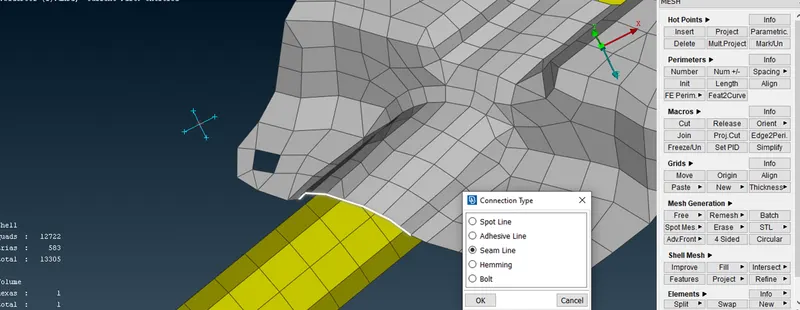
- We shall be looking at seam and spot weld connections . in the case of seam welds , the basis is creating the weld locations from curves basis is creating weld location from curves derived from the particular feature
- We using the MESH MODULE > PERIMETERS > FEAT2CURVE option . this will let us select the edge and derive a curve
- Then using the convert tool that was used earlier, the curve can be converted into seam line
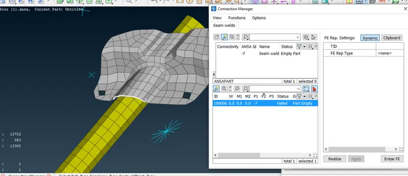
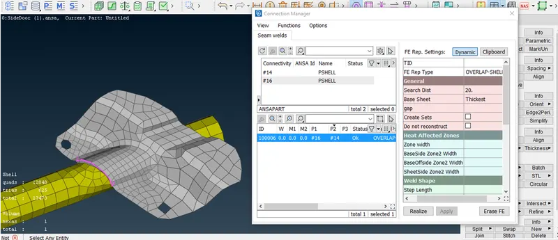
- Again , as before we make use of the connection manager .The seam line selected and proceed and assign P1 and P2 are selected .
- The FE Rep type here would be OVERLAP shell since both layers are parallel to each other
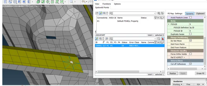
- Next Spot welds , we shall be making use of the COG tool again to create 3D points . These 3D points are then converted into 'SPOT WELD' .
- After conversion, its the same process of accessing the connection manager and assigning properties
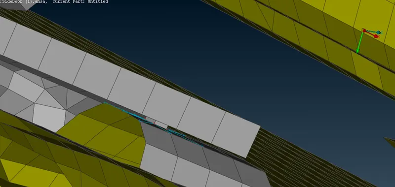
- This time , since it's a spot weld , the FE Rep type would be RBE3 >HEXA >RBE3 . then assingn the P1 and P2
- A PSOLID will be need to be created and assigned.
CBUSH CONNECTION
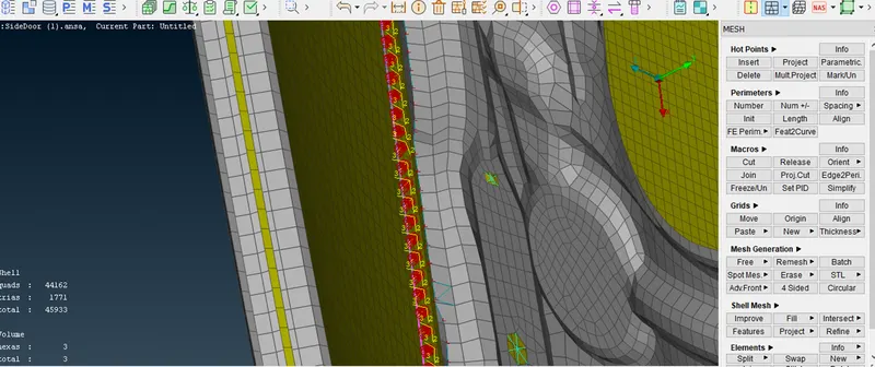
- The next type of connection would be that of CBUSH RBE3 elements, which will be used wherever window weather strips are involved.
- To begin , the perimeter of the glass components is used to create curves. for this, PERIMETER > FEAT2CURVE tool is used to select and create them
- Selecting the curves , they can be converted into SPOT LINES using CONVERT > CURVES tool.Each curve need to be selected separetly and converted
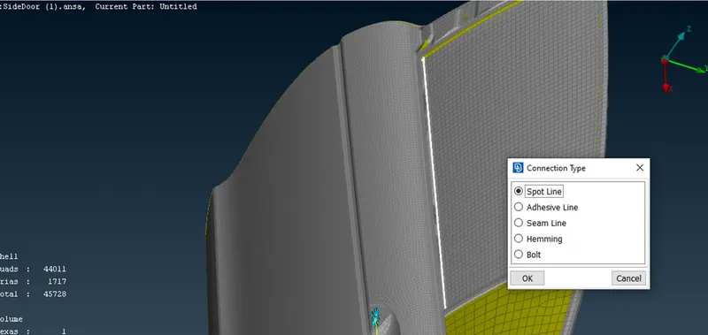
- After converting them , we avail the help of the connections manageer again to create these CBUSH connections . The process will be repeated for each curve
- Then we need to select the P1 and P2 as usual . Need to assign the spacing value . The FE Rep type would be RBE3-CBUSH-RBE3
- We can proceed to create a BUSH ID . In the PBUSH ID. The ID will be requires 6 stiffness values and they can be entered
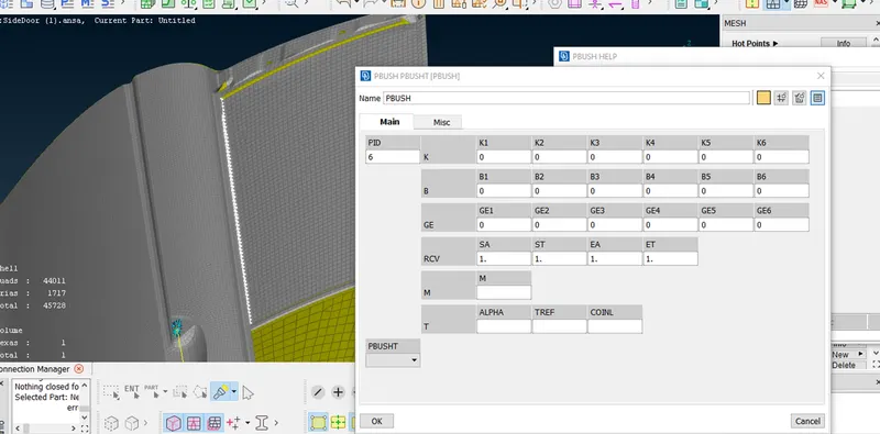
- This we can go ahead and apply and Realize the connection .
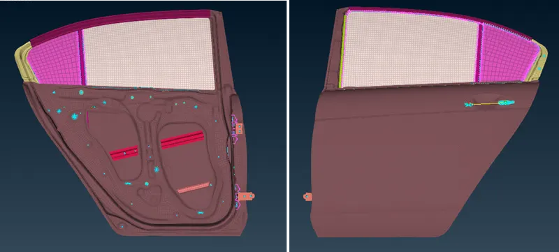
FINAL MODEL IMAGE
LEARNING OUTCOMES :
- Learned about various connections available in the NASTRAN deck
- Learned to convert curves and points into connection lines / points
- Learned to assign properties to connections and edit connections as per requirements
- Learned about the concepts of weather stripping and its importance, along with the concept of tailor welds
Conclusion :
- Suitable connections were deployed between various components in the rear door model after PIDs were assigned to each component.