Week 4-1D Element Creation Challenge
Objective:
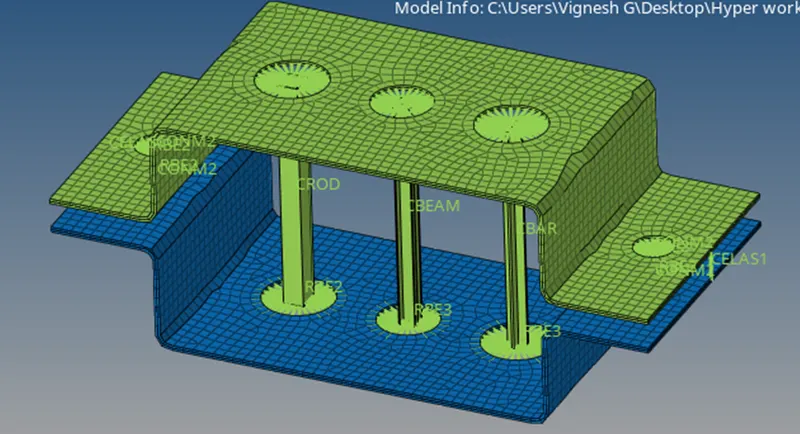
- To create the 1D element for given component with given cross section and DOF
- Rod element - Translational DOF should be constrained with RBE2 link ( at A )
- Beam element - All elements should be constrained with the RBE3 link ( at B )
- Bar element - Constrain only X and Y DOF's with RBE3 link ( at C)
- Apply the mass of magnitude 10 with RBE2 link ( at D & E )
- Join the two components with Spring elements ( at F )
Introduction:
- 1D elements can be applied to 2D and 3D model by analyzing the indiviual line element that form the model's infinite element mesh .
- 1D elements are useful for stimulating how different section of the mesh will react to certain condition
- 1D elements are basically line shaped element which are created by two nodes
- Example of 1D elements are RBE2,RBE3,ROD,BAR,BEAM,SPRING element
Procedure :
- Initially the given model imported as per standard
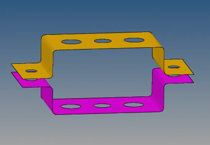
- Using the midsurfacing option midsurface created for each component ( to convert the 3D component to 2D shell component )
- To creating material property for given component as Steel and its updated ( since no any material type mentioned )
- start to automesh for given component while selecting all the surface . before the mesh create Washer split provided for each hole area
- Mesh element size are 5 unit with mixed elements. Element size adjusted to improve the mesh quality in hole area.
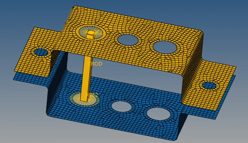
- Rod element ( at A )
In 1D menu creating a rigid element link (RBE2 Link ) at A with help of rigid element option . And , Translation DOF constrained with RBE2 link.
Rigid element created as CROD at A and Cross section has been created using hyperbeam option as per given dimension.
Property for ROD element created and updated .
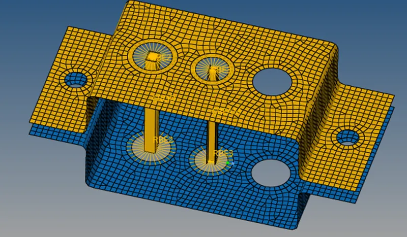
- Beam element ( at B )
Same as Rod element here RBE3 link created at B with help of RBE3 option. And, all DOF constrained with RBE3 link.
RBE3 element created as CBEAM at B and cross section has been created using hyperbeam option as per given dimension.
Property for BEAM element created and updated .
- Bar element ( at C )
Here RBE2 link created at C with help of rigid option . And , X and Y DOF only constrained with RBE2 link
Rigid element created as CBAR at C and cross section has been created using hyperbeam option as per given dimension.
Property for BAR element created and updated.
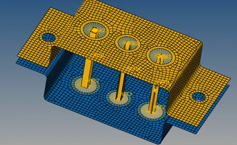
- Applying Masses at D & E
Here RBE2 link created at D & E with help of Rigid option. all DOF constrained with RBE2 link.
Element created as CONM2 at D & E area and mass applied with magnitude of 10
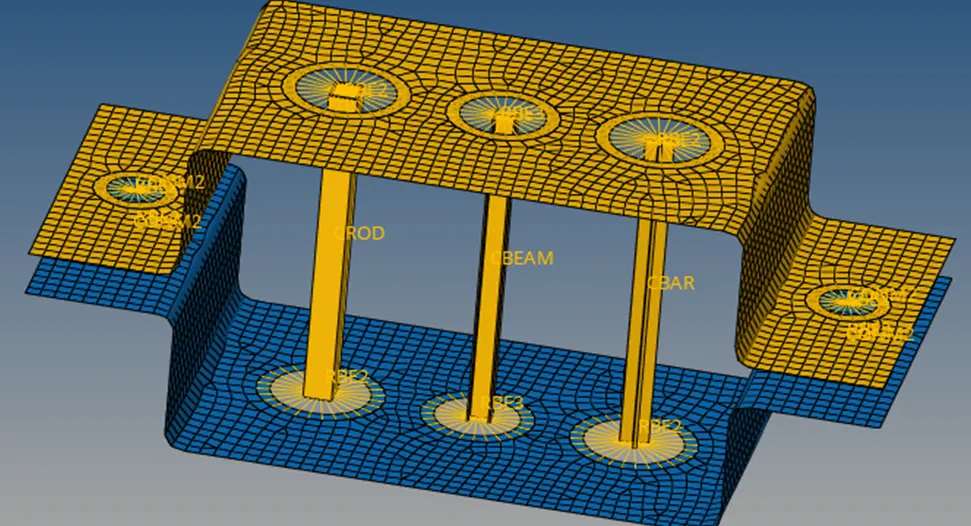
- Joining the two components with spring element at F
Here spring element has been created with help of spring option at F section
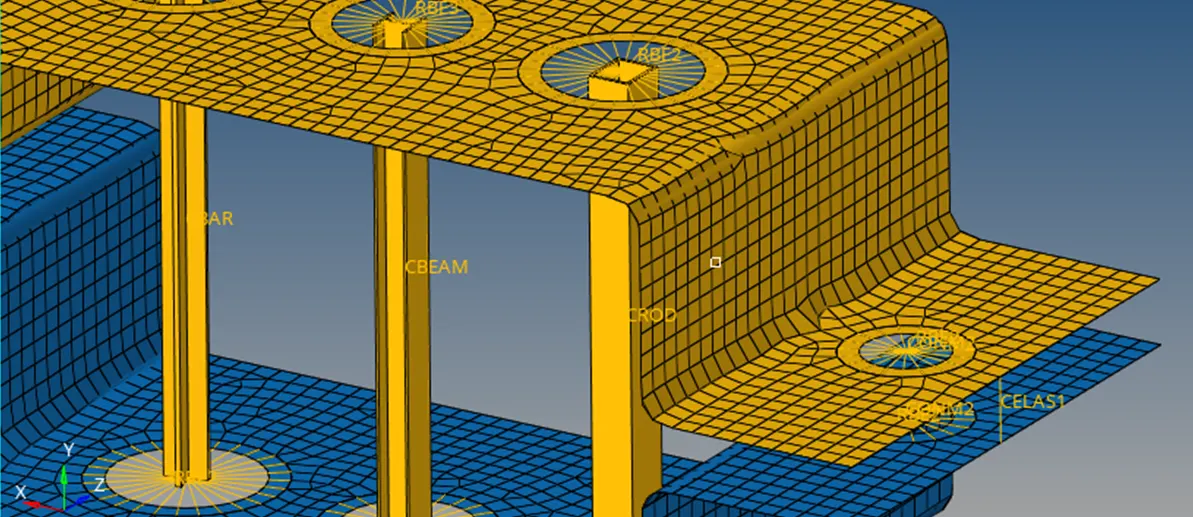
Result:
- ROD element as given dimension with RBE2 link created and Translational DOF constrained with RBE2 link successfully at A section
- BEAM element as given dimensionn with RBE3 link created and all DOF constrained with RBE3 link successfully at B section
- BAR element as given dimension with RBE2 link created and X and Y DOF constrained with RBE2 link successfully at C section
- Mass has been applied with magnitude of 10 successfully at D & E section.
- Joining the two components with spring elements created successfully at F section
Final Image: