Week 6 - Creating connection for Rear door
Objective:
For the given model, create and Apply different PIDs for different components. By using the same technique and the elements as shown in the video, Perform suitable connections.
Procedure:
- Firstly, import the given FE model into the Ansa software.
- After importing the FE model, set Property ID for different components on the given FE model.
- After setting the PID's for the components on the model, create connections for the model wherever needed.
- Firstly, start by creating Rigid body connections (RBE2) by giving the connections wherever required.
- Select the Nastran deck ---> Elements --> RBE2 --> Many nodes --> select the nodes on the surface where you want to create RBE2 elements & click on the OK button. The connection is created on the selected surface.
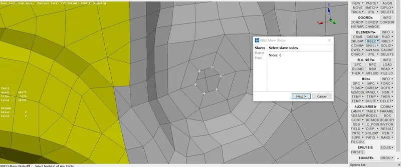
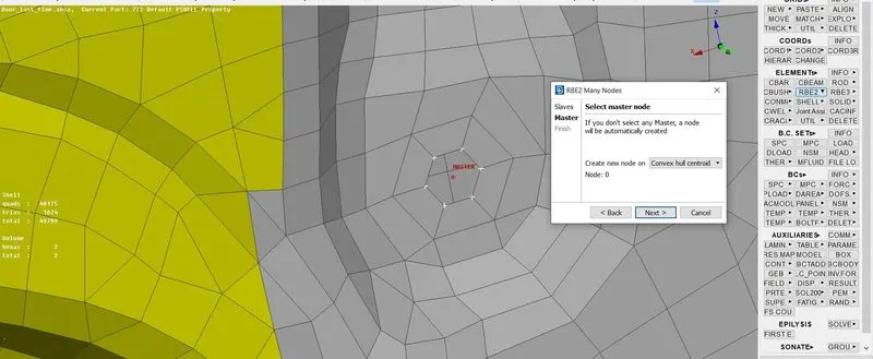
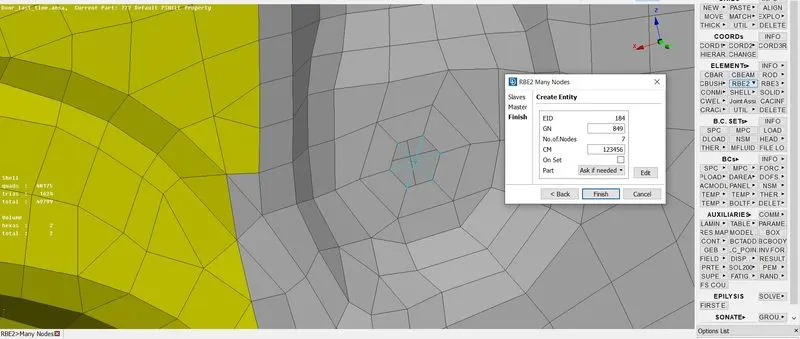
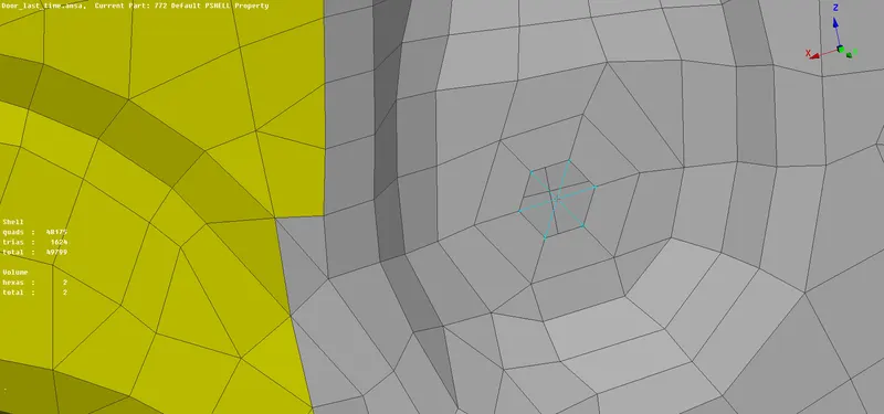
PROCESS OF CREATING AN RBE2 CONNECTION FROM START TO END IN ANSA
- In order to connect two components, we can also create bolted connections in Ansa.
- Firstly, identify the components on the model where can we create bolted connections.
- Switch from the Nastran deck to the Topo deck and select the ONCOG option present in the Points tools.
- Select the Edges in the ONCOG option and select the entire edges of any circular surface and enter the Diameter value as ZERO in the pop-up box and middle-click to confirm.
- A COG point is created in the middle of the selected circular surface.
- Select the Convert option in the Assembly tools which is present at the top of the window to convert the 3D point to Bolt connection type.
- Select the convert option and select the option 3D points from the list of commands available. Select the point and click enter on the keyboard in the popup window select the option Bolt and click Ok.
- Click on the connection manager in the assembly tools present at the top of the window and select the converted bolt point and press the enter on the keyboard to confirm.
- After pressing the enter button, the connection manager window will be popped up in that select the Bolt option from the list of the options available in the FE Rep type & in the Zones select the IN/OUT X, give the proper value in the search distance option.
- Select the components in the P1, P2, P3 & P4 of where you want to create a connection.
- Click on the P1 and press right-click in that and press the F1 function key on the keyboard and select the component and click Ok.
- In the same way, select the P2, P3 & P4 for the components and click Ok.
- After selecting all the components and entering the values in the necessary positions click on the apply button and then click on the realize button the bolt connection is realized and can be seen on the selected components.
- The Connections cannot be created if there are more than 4 components.
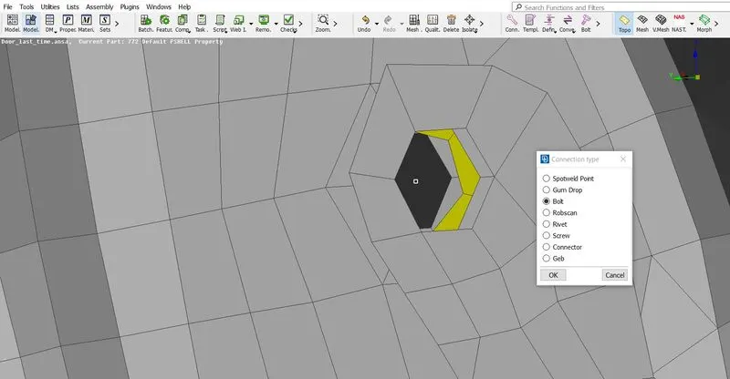
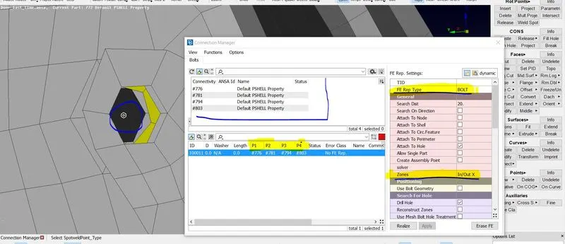
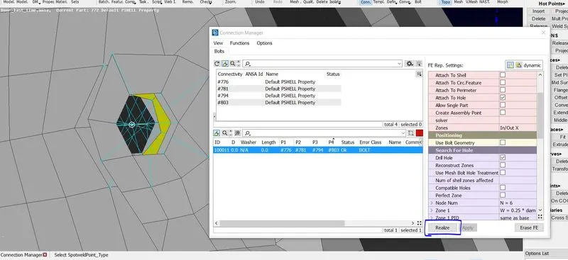
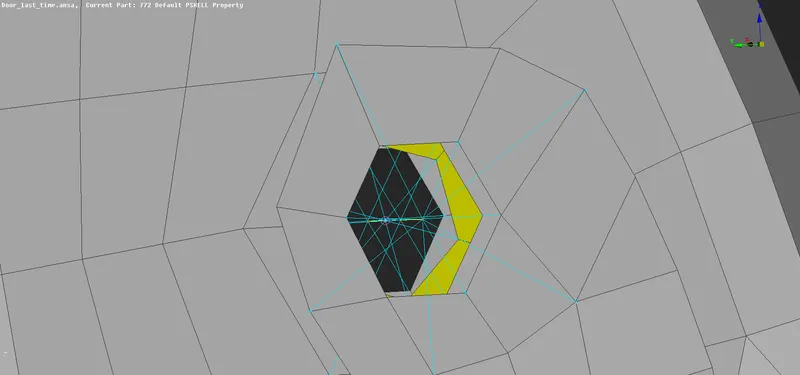
SCREENSHOTS OF STEP BY STEP PROCEDURE OF CREATING A BOLT CONNECTION
In the same way, create the bolt connections wherever required.
- After this, the door handles should be captured with rigid elements with a mass assigned to them.
- Firstly, capture the door handles with RBE2 elements with many nodes option by selecting the entire feature.
- After capturing the door handles with RBE2 elements try to create a handle with the same RBE2 elements by using the Two nodes option in it.
- Select the Two nodes option then select the master node of the two previously created RBE2 elements and click Ok to confirm the procedure. There is a master node created in between the door handle.
- The Mass is assigned to the door handle by using the CONMi2 option in the CONMi tools present in the Elements in the NASTRAN deck.
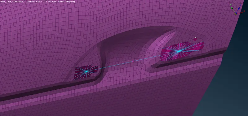
THE DOOR HANDLE IS CREATED WITH RBE2 ELEMENTS AND THE MASS IS ASSIGNED
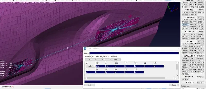
CONMi POPUP WINDOW
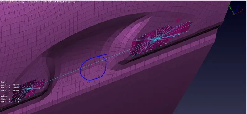
THE MASS IS ASSIGNED TO THE NODE IN BETWEEN 2 RIGID BODY ELEMENTS
- The hinge support of the door in which direction the door will be opened will also be created by using the RBE2 elements. Create the rigid elements on the feature and with the many nodes option in the RBE2 command in the elements tools in the Nastran deck.
- After creating the RBE2 elements for the entire feature and then with the Two nodes option in the RBE2 command try to connect the two rigids by selecting the two master nodes of the already created rigid body elements.
- In order to move the door in the specified axis that is in the global Z-axis, try to release the rotational degree of freedom for the created rigid body elements.
- Click on the Info tool in the Elements and click on the created RBE2 connection and in the CM option try to release the rotational DOF in the Z-axis by deleting the value of 6 in the box.

A RIGID CONNECTION IS CREATED FOR THE HINGE SUPPORT TO OPEN THE DOOR
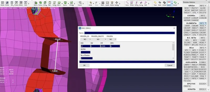
THE ROTATIONAL DOF IN Z-AXIS (6) IS RELEASED BY USING THE INFO OPTION
- A Spot weld connection is created for the rails & it is created with the RBE3-HEXA-RBE3 connection.
- Firstly, Select the Edges in the ONCOG option and select any element on the component and enter the Diameter value as ZERO in the pop-up box and middle-click to confirm.
- A COG point is created in the middle of the selected element.
- Select the Convert option in the Assembly tools which is present at the top of the window to convert the 3D point to Spot weld connection type.
- Select the convert option and select the option 3D points from the list of commands available. Select the point and click enter on the keyboard in the popup window select the option spotweld and click Ok.
- Click on the connection manager in the assembly tools present at the top of the window and select the converted spot weld point and press the enter on the keyboard to confirm.
- After pressing the enter button, the connection manager window will be popped up in that select the RBE3-HEXA-RBE3 option from the list of the options available in the FE Rep type & enter the proper value in the search distance option and also give the feature angle as 20 and then create a new PSOLID ID in the specified area.
- Select the components in the P1 & P2 of where you want to create a spot weld connection.
- Click on the P1 and press Right-click in that and press the F1 function key on the keyboard and select the component and click Ok.
- In the same way, select the P2 for the components and click Ok.
- After selecting all the components and entering the values in the necessary positions click on the apply button and then click on the realize button the spot weld connection is realized and can be seen on the selected components.
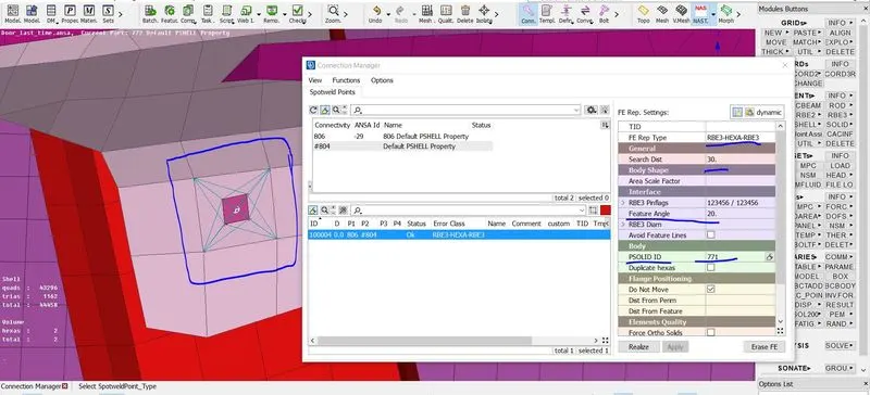
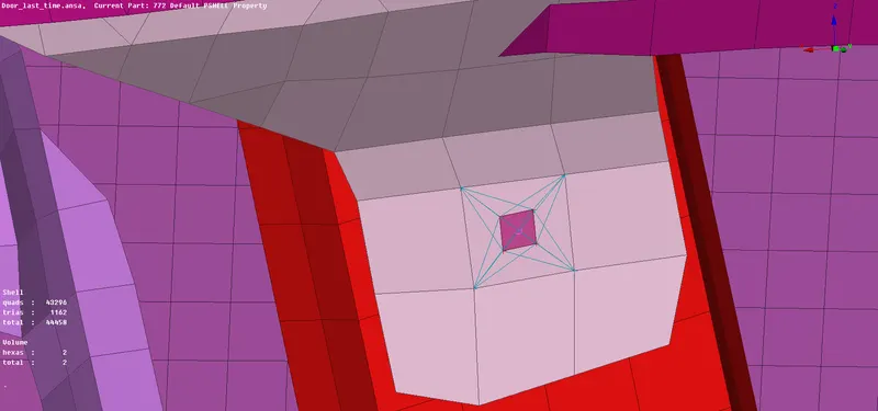
SPOT WELD CONNECTION ON THE RAIL COMPONENT
- After creating the spot weld connections wherever required, try to constrain the movement of the windows of the side door.
- Firstly, create the curves for the windows by using the cons2curve option present in the curves in the Topo deck.
- Select the FE line of the windows as a reference and Middle-click to convert the Cons to the Curve.
- After taking all the curves and select the curves and connect them by using the Multi connect in the Connect option in the Curves tools.
- After converting the CONS to curves, convert the curve to the spot line.
- Select the Convert option in the Assembly tools which is present at the top of the window to convert the curve to Spot line.
- Select the convert option and select the spot line from the list of commands available.
- Select the curve and click enter on the keyboard in the popup window select the spot line and click Ok.
- Start creating the connections on the spot line individually.
- Click on the connection manager in the assembly tools present at the top of the window and select an individual converted spot line and press the enter on the keyboard to confirm.
- After pressing the enter button, the connection manager window will be popped up in that select the RBE3-CBUSH-RBE3 option from the list of the options available in the FE Rep type & enter the proper value in the search distance option and also check the options in the RBE3 pin flags and then create a new PBUSH ID in the specified area.
- In the PBUSH ID, press the shift + ? in the keyboard and click on the New and a pop-up window will appear in that enter the values for the K1, K2, K3, K4, K5 & K6 and then click on the OK.
- After this, double click on the created PBUSH ID, it will revert to the connection manager window.
- Select the components in the P1 & P2 of where you want to create a spot weld connection.
- Click on the P1 and press Right-click in that and press the F1 function key on the keyboard and select the component and click Ok.
- In the same way, select the P2 for the components and click Ok.
- After selecting all the components and entering the values in the specified areas click on the apply button and then click on the realize button the CBUSH connection is realized and can be seen on the selected components.
- Perform the same procedure for all sides of the side door window individually by taking FE references.
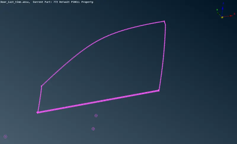
CONVERTED CURVE TO THE SPOT LINE BY USING THE FE REFERENCE OF THE SIDE DOOR WINDOW
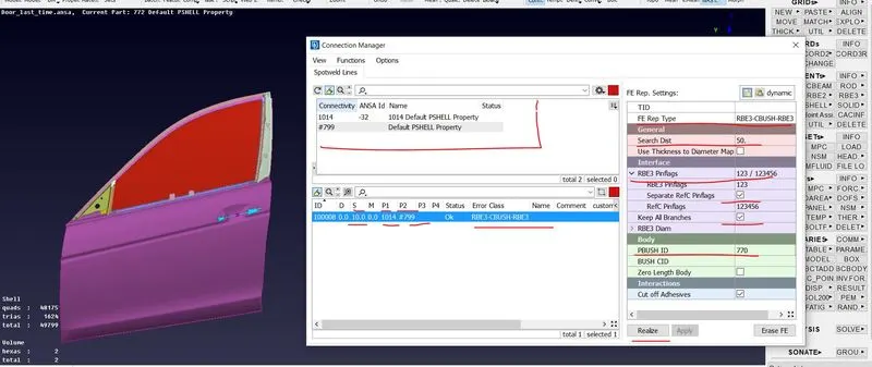
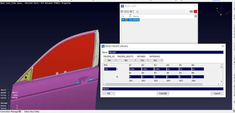
PBUSH ID IS CREATED AND THE VALUES ENTERED IN THE SPECIFIED AREAS OF THE K1, K2, K3, K4, K5 & K6
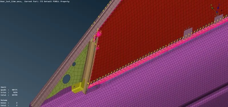
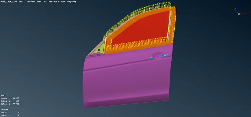
THE CBUSH ELEMENTS ARE CREATED ON THE WINDOW OF THE SIDE DOOR
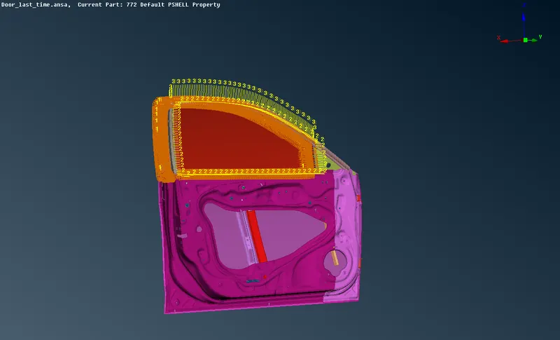
THE GIVEN MODEL WITH ALL THE NECESSARY CONNECTIONS CREATED
All the necessary connections have been created on the given side door model.
Conclusion:
For the given model, the PID's are created and assigned for the different components in the model & also the different connections like spot weld, bolt connection etc have been created for the different components wherever required in the model as shown.