Creating connection for Rear door
AIM:
- To make Appropriate Connections on the Rear Door Model and to Learn the use of different connections in the ANSA Software using the NASTRAN Deck.
OBJECTIVES OF THE PROJECT:
- To make Rigid Connections on the Rear Door Model.
- To make Connections on the Hinges part using RBE2 Many Nodes and Two Nodes option.
- To make Weld Spot Connections wherever necessary.
- To make CBUSH Connections on the Window Glass.
PROCEDURE
- First Step is to Import the Model into the ANSA Software.
- Go to TOOLS > GEOMETRY > CHECKS > EXECUTE to check the Geometrical Errors.
- As the Rear Door model is already Meshed we have to make Connections only.
- So to start with connections we have to first set PID for every part.
- Go to MESH MODULE > MACROS > SET PID > SELECT THE PART > MIDDLE MOUSE BUTTON > RIGHT CLICK > NEW PID > OK.
- In this manner set different PID for every part.
- Then switch to NASTRAN Deck.
- To connect hinge areas go to ELEMENTS > RBE2 > MANY NODES > FEATURE SELECTION > LOOP > SELECT THE EDGES > OK.
- The Connection is made as show in the image.
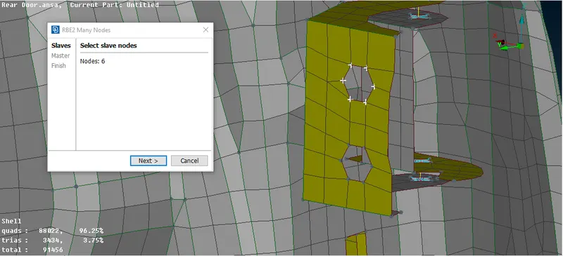
- Similarly, connect the bottom edges.
- Then go to ELEMENTS > RBE2 > TWO NODES > SELELCT THE TWO MASTER NODES > OK.
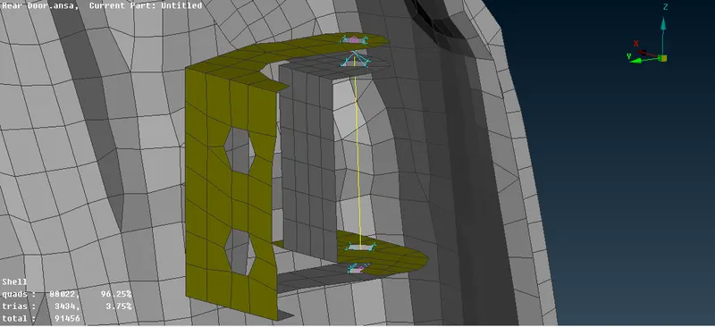
- In the connection info tab constraint the degree of freedom up to 5 and allow the rotation along the Z axis.
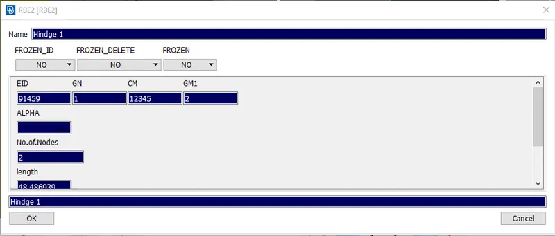
- Similarly, connect at the bottom hinge.
- Then, to make Bolt Connections go to TOPO MODULE > POINTS > ON COG > EDGES and select the edges, a 3D point is created.
- Go to ASSEMBLY > CONVERT > 3D POINT > SELECT THE POINT > BOLT.
- Go to ASSEMBLY > CONNECTION > SELECT THE POINT > MIDDLE MOUSE BUTTON > ENTER THE P1 AND P2 VALUES > SELECT BOLT > OK.
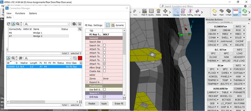
- Make RBE2 connections as Cluster RBE2 where bolts are to be fastened on the door frame.
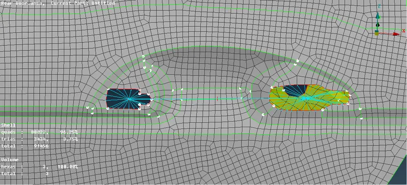
- At the handle section make Cluster RBE2 and connect both the Master nodes together with the RBE2 element.
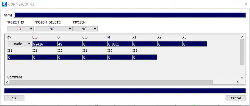
- Go to NASTRAN > ELEMENTS > CONMi > CONM2 > NODES > ENTER THE MASS VALUE AS 0.0001 > OK.
- The mass entered is in tonnes.
- At the Rod part create a 3D Point and then go to ASSEMBLY > CONVERT > 3D POINT > SPOT WELD > OK.
- Then go to ASSEMBLLY > CONNECTIONS > 3D POINT > ENTER P1 AND P2 VAULES > RBE3 HEXA RBE3 > NEW SOLID PID > APPLY > REALIZE.
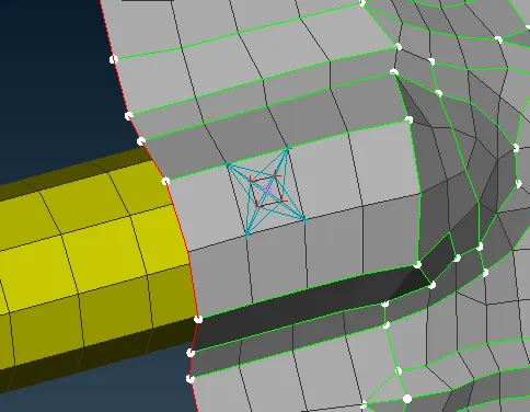
- In this way spot weld connections are created where there are no bolt connections available.
- In areas where spot weld could not be created connect the Part with RBE2 > MANY NODES.
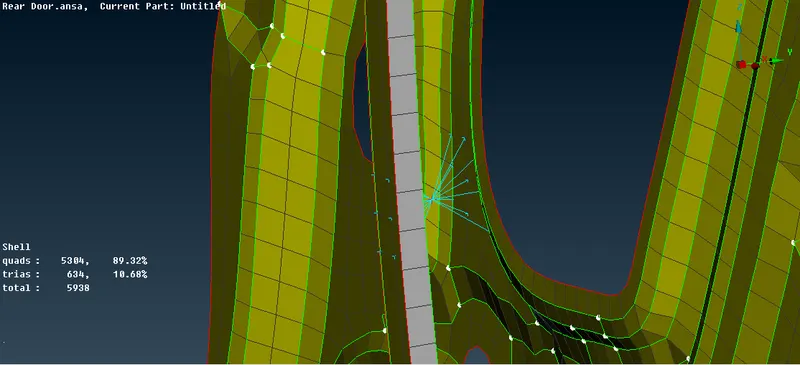
- Now to create bush connection at the window glass parts go to MESH MODULE > PERIMETERS > FEAT2CURVE > FEATURE > SELECT THE GLASS EDGES > OK.
- Similarly, create all the glass edges to curves.
- Go to ASSEMBLY > CONVERT > CURVES > SPOT LINE.
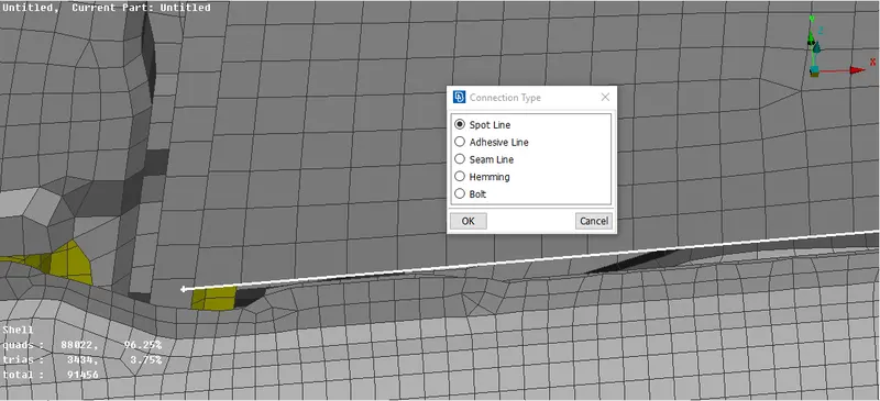
- Then go to ASSEMBLY > CONNECTIONS > CURVE > RBE3 CBUSH RBE3 > NEW PID > APPLY > REALIZE.
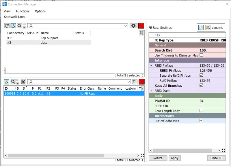
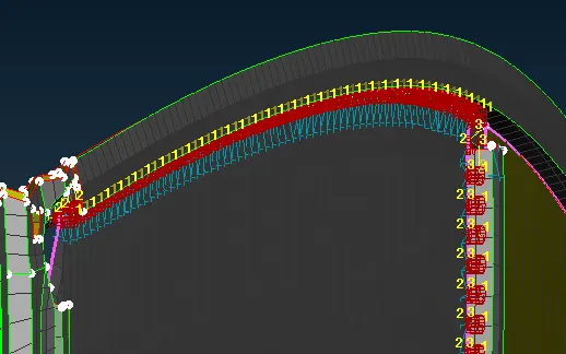
- Hence the CBUSH element connection is created.
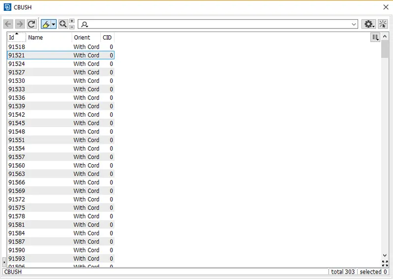
- Then go to CBUSH DATA > MODIFY > ORIENT > WITH CORD > CID > 0 > OK.
- With this modification all the Local Coordinates are converted to the Global Coordinates.
- Check whether all the connections are made.
- Then go to FILE > SAVE to save the model.
LEARNING OUTCOMES:
- Different connections such as bolt, spot weld, seam weld, cbush, etc.
- Use of the connections according to the Geometry.
- Bolt connections with Washer elements.
- Constraining the Degrees of Freedom of the connections.
CONCLUSION:
- We conclude that the connections in the model are provided.
- Use of different connections is according to the Geometry.
- In the areas where the spot weld connection cannot be created, we can create a rigid connection using RBE2 element.