Extracting Mid-surface, Meshing and Deploying connections on the Seat model
AIM:
- To extract the mid-surface for the seat model and to deploy Mesh for the mid-surface, for closed volume deploy volume meshing. To deploy Bolt as well as Seam Weld connections according to the parent Geometry.
OBJECTIVES OF THE PROJECT:
- To check for geometrical errors and if any eliminate them.
- To extract mid-surface for the seat model parts.
- To deploy mesh for the extracted mid-surface.
- To deploy volume meshing using ORTHO TRIA for closed components.
- To assign PIDs.
- To deploy bolt connections.
- To deploy weld connections.
- To assign thickness.
PROCEDURE:
- First step is to import the SEAT MODEL into ANSA software.
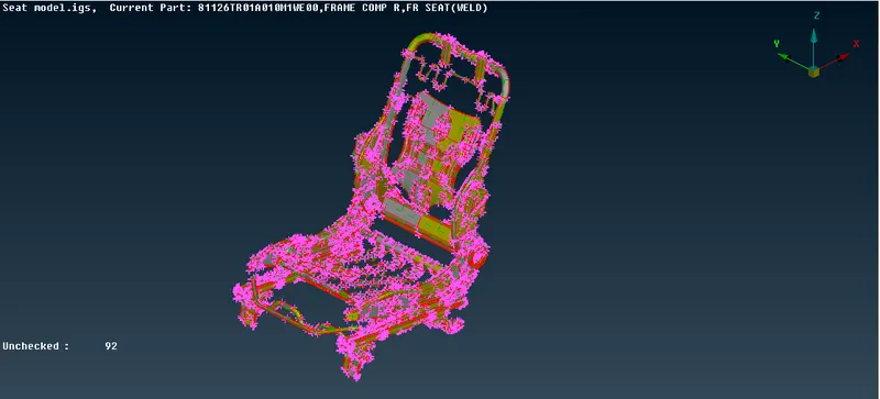
- Go to FACES > TOPO > SELECT > OK.
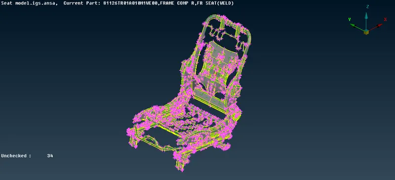
- This option will stitch all the faces together.
- Go to UTILITIES > MESH PARAMETERS and enter the following values :
Target/Average Length = 3mm.
Go to UTILITIES > QUALITY CRITERIA and enter the following values :
Minimum Length: 2
Maximum Length: 5
Maximum Aspect: 3
Warpage: 15
Skewness: 45
Jacobian: 0.7
Minimum quad angle: 45
Maximum quad angle: 135
Minimum tria angle: 30
Maximum tria angle: 120
Tria Percentage: 15
- Go to MESH MODULE > LENGTH > PRRIMETERS > 1MM > MACRO 1MM > OK so that all the length of the mesh perimeters is converted to 1mm.
- After the length is converted to 1mm the model is refined and now checks for disturbed faces.
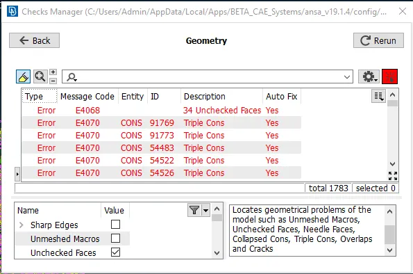
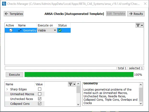
- Go to TOOLS > GEOMETRY > CHECKS > EXECUTE to check the Geometrical Errors. If any eliminate them with Auto-fix option.
- Go to UTILITIES > MEASURE and measure the thickness of each of the component.
- Go to TOPO > FACES > OFFSET to manually offset the faces.
- Start working with smaller regions to offset the faces and offset the total component.
- This will convert the model into 2D.
- A second Method to create an auto-mid is using MIDSURFACE > SKIN.
- Go to FACES > MIDDLE > MULTI and create middle faces for the features and the ribs.
- Now for Torsional springs go to CURVES > MIDDLE to create middle curve.
- Go to CURVES > CONNECT > MULTI to connect all the curves and convert them as a single entity.
- After Mid-surface is created go to MESH MODULE.
- As the component is complicated and large, Manual Meshing may consume time and hence we go for Batch Meshing.
- For this go to LISTS > MODEL BROWSER > SET PART > NEW > MIDSURFACE > OK.
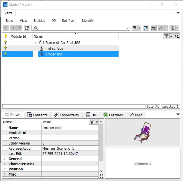
- This will assign the extracted mid-surface as a new part.
- Then go to TOOLS > BATCH MESHING > NEW > MESHING SCENARIO > MIDSURFACE > GREEN ARROW > OK > CHECK MESHING PARAMETERS AND QUALITY CRITERIA > RUN.
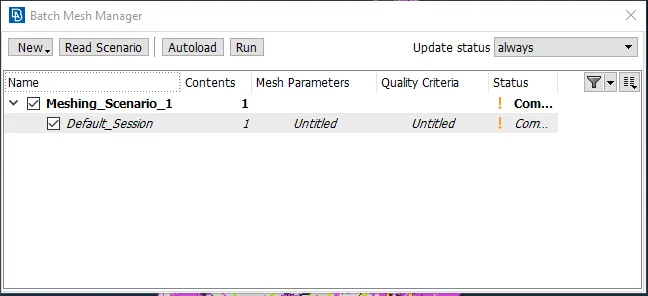
- Using batch meshing option ANSA will auto-mesh the whole component within few minutes of time.
- This will reduce a lot of time on meshing instead of manual mesh.
- Now as ANSA has generated an auto-mesh on the component go to DRAWING STYLES > HIDDEN to check for the OFF ELEMENTS.
- The quality of the mesh should be increased manually.
- Use RECONSTURCT and SMOOTH option to improve the quality of the mesh.
- Try to keep the off elements as low as possible.
- After all the meshing is completed go to TOPO > FACES > SET PID and select the mid-surface to set property ID. Set separate PID for each component.
- Then go to properties and set thickness for the component. The thickness should be as measured earlier.
- For components for which mid-surface generation is not possible or which have closed envelope, deploy volume meshing.
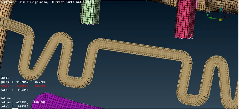
- For spring elements, go to NASTRAN DECK > ELEMENTS > CBEAM > CURVE (BOX) > SELECT CRUVE > ORIENT WITH VECTOR > SPECIFY ELEMENT LENGTH > OK. This will Deploy 1D mesh on the spring middle curve line.
- Go to PROPERTIES > SELECT SPRING > NEW > CBEAM > ASSIGN RADIUS > OK. Ansa will calculate the area for the beam with respect to the Radius data entered.
- Similarly, deploy 1D meshing on all the spring elements.
- Go to UTILITIES > QUALITY CRITERIA > PRESENTATION PARAMETERS > LINE ELEMENTS > AS SOLID > OK. This will represent the spring elements as solids.
- Now to deploy connections, switch to NASTRAN Deck.
- To connect go to ELEMENTS > RBE2 > MANY NODES > FEATURE SELECTION > LOOP > SELECT THE EDGES > OK.
- Then, to make Bolt Connections go to TOPO MODULE > POINTS > ON COG > EDGES and select the edges, a 3D point is created.
- Go to ASSEMBLY > CONVERT > 3D POINT > SELECT THE POINT > BOLT.
- Go to ASSEMBLY > CONNECTION > SELECT THE POINT > MIDDLE MOUSE BUTTON > ENTER THE P1 AND P2 VALUES > SELECT BOLT > OK.
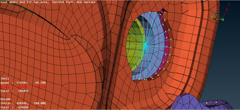
- Make RBE2 connections as Cluster RBE2 where bolts are to be fastened on the seat frame.
- For seam weld connections, go to TOPO > CURVES > CONS2CURVES > OK. This will create curve for welds.
- Go to ASSEMBLY > CONVERT > CURVE > SEAM LINE > OK.
- Then go to ASSEMBLY > CONNECTION > SELECT THE SEAM LINE > MIDDLE MOUSE BUTTON > ENTER THE P1 AND P2 VALUES > OVERLAP SHELL > SEARCH DIST = 10 > WIDTH=3 > ASSIGN NEW PID > ENTER THICKNESS > ACCEPT > REALIZE. This will create a 2 D weld representation.
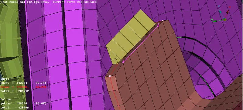
- Go to UTILITIES > QUALITY CRITERIA > PRESENTATION PARAMETERS > DRAW SHELL AS SOLID > OK.
- Go to FILE > SAVE.
CONCLUSION:
- In this way by completing this Project, we understand mid-surface extraction, Shell Meshing, Volume Meshing, Bolts connections, Weld connections, assigning thickness,etc.
Link for model:
https://drive.google.com/file/d/12Isq_AOZpMnNlsNvt5m8XfD6Z6ZXy31h/view?usp=sharing