Midsurface for Hood Model
Aim : To create midsurface for the Hood Model (sheet-metal component) and perform preprocessing for the component with proper mesh flow by using the ANSA tool and assign appropriate thickness.
Procedure : The procedure includes following steps -
- Importing the CAD model in the ANSA software.
- Perform TOPO operation by using 'Faces > TOPO'. Select all the entities and click on OK.
- Check for the Geometrical errors by using 'Checks > Geometry' in the Tools menubar.
- If any errors found Fix them with 'Autofix'. If needed clear the geometrical errors manually.
- Enter 'LENGTH' as 5 mm from 'PERIMETERS' in Mesh view.
- Inspect the no of components in the CAD model by using 'Lists > Properties'.
- Select the Hood form the Properties by enabling the bulb.
- Make sure all other component bulb are switched off so that work is performed only on the hood component.
- To start with the Hood first Measure the Thickness of the component at 4-5 Random Points.
- To Measure the thickness select 'Utilities > Measure'.
- The thickness of the component is found to be 0.75 mm.
- The Component is found to be Symmetric, so to reduce the meshing time delete the half part by using 'Faces > Delete'.
- Now as the thickness is 0.75 mm, the Hood is a sheet metal component and to perform Meshing on such Components we convert the 3D Model into a 2D model by creating a midsurface for the entire component.
- To create midsurface select 'Faces > Mid Surface > Skin'. Assign thickness as 0.75mm.
- To reduce time and eliminate manual errors go with the Skin option.
- Now the Midsurface is created. Check the Geometry again. Unselect Single Cons from the Check Menu.
- Now enter the Quality Parameters by selecting 'Utilities > Quality Criteria' and assign the given Quality Criteria values.
- Select 'Utilities > Mesh Parameters' and enter the values as 'Length=5;Min Length=2;Max Length=7'.
- Before Meshing Defeature the curve portions by creating 'Faces > Cut' at the peak of the curve and supressing the adjacent parallel lines.
- Defeature the areas where the quality creiteria would fail.
- Make sure all the features like cirles would have an even no of hot points.
- Select 'Mesh > Perimeters > Slide' and align the circles parallel to the perimeter lines.
- Select 'Hot Points > Mark' and mark all the circle points.
- Now supress the unnecessary construction lines and make horizontal cuts to get a better mesh flow.
- Select 'Mesh Generation > Best > Select' and select the faces to be meshed. Start Meshing with the Features areas and then Mesh the less Complicate areas.
- Select 'Shell Mesh > Recostruction' and select 'Feature Selection > Macro' to remesh all the entities within the selected construction lines.
- Eliminate opposite trias either by 'Elements > Split' if two trais are facing each other or 'Grids > Paste > Paste node pairs > COG' if two trais are facing away from each other.
- If a tria element is lying between the face we can eliminate it by using 'Elements > Split > Edges' by taking the trai to the perimeter.
- For the trais at the perimeters can be swapped by using 'Elements > Swap' and can be arranged so that all the trais are facing towards a single direction.
- For the fillet regions should have two no of rows. If not create additional row by using 'Elements > Split > Edges'.
- It is found that Meshing smaller and parallel regions by making cuts result in Better Mesh Flow and lesser trais.
- After every small changes select 'Shell Mesh > Smooth'. Select the entities and click on OK.
- To Check for the OFF elements in the Quality Criteria turn on 'Drawing Styles > Hidden'.
- Check for the Elements Failing for Quality and Eliminate them by 'Shell Mesh > Smooth'.
- Reconstruct the ares by selecting 'Shell Mesh > Recostruction > Feature Selection > Entities'.
- When the Hood component is Meshed completely Strat Meshing with the small three components and then Mesh the Hood Support Frame by following the above steps.
- For the smaller components the thickness is found to be 1.2 mm.
- For the Hood Support Frame the component is found to be symmetric except the lock Portion.
- Select 'Focus > Not' and select the lock region and click the middle Mouse Button.
- Now to Reduce Meshing time select 'Faces > Delete' and delete the half Portion.
- Create Midsurface by 'Faces > Mid Surface > Skin'. Assign thickness as 0.75mm.
- Defeature the Curve areas and Mesh the Component using 'Mesh Generation > Best > Select'.
- Remove all the OFF elements and obtain a better Mesh Flow by following the above steps.
- After the Meshing is done select 'Utilities > Transform > Copy > Symmetric > OK'.
- Perform the above step for the Hood component and now both the components are satifying the Geometries.
- In the Hood support Frame component select 'Focus > Neighbours > All'. Now mesh the lock Region and the whole CAD Model is Meshed.
- Final Geometry Checks, Quality Creiteria, Off Elements are Performed.
- To Enable Draw shell as solid after finishing the Meshing, select 'Utilities > Quality Criteria > Presentation Parameters > Draw shell as solid > Apply > Ok'.
- Final Step is to Save the File. Select 'File > Save'.
Images :
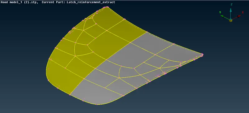
Without topo Cleanup
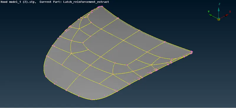
With topo cleanup and orient
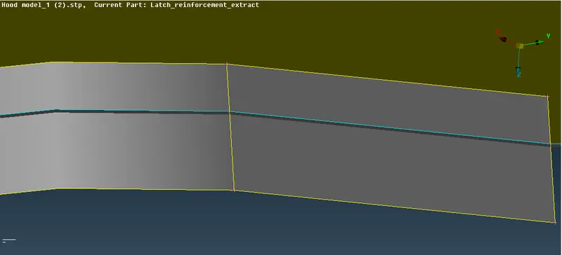
With triple cons
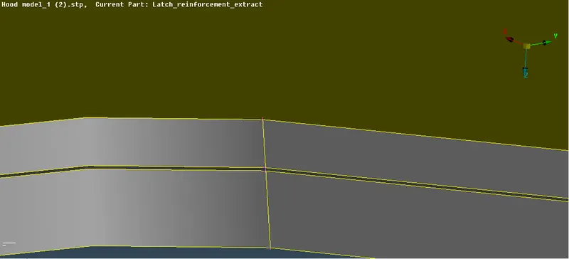
Triple Cons Removed
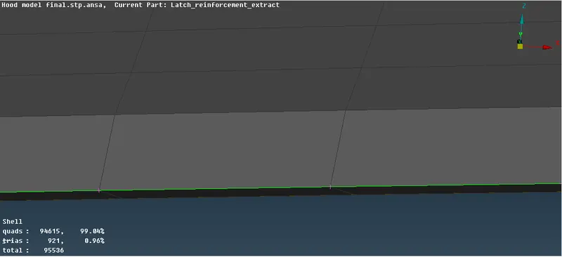
FE Model without thickness and Draw shell as solid
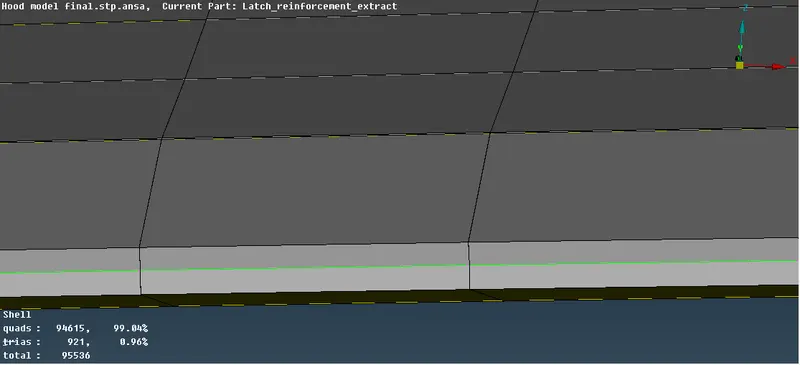
FE Model with thickness and draw shell as solid
Learning Outcomes :
- Geometry cleanup.
- Manual Geometry cleanup and Autofix Geometry cleanup.
- Releasing Triple Cons.
- Defeaturing Curve portions.
- Meshing technique.
- Eliminating Opposite trais.
- Using Split, Swap and Paste option for eliminating trais.
- Quality Criteria Checks.
- Mouse Controls.
- Midsurface Extraction using Skin option.
- Providing PID and thickness to the Midsurface.
- Draw Shell as Solid option.
- Trais per node should be less than 2.
- Mesh flow should be such that the trais should face in one direction.
Conclusion :
By completing the Hood Project we conclude that the Hood Model is Pre-processed by Meshing in ANSA and ready for processing.