Week 6:- Clamp Unit & Pin-Clamp Unit Design Challenge
Aim/ Objective:
The main objective of this project is to -
- To Design 3 Different types of Swivel Clamp Unit with Different Riser, Blade, and Clamp Arm for the given Car Panel.
- To Design a Pin-Clamp Unit for the given Car Panel.
- To maintain the stroke as 100mm.
INTRODUCTION:
A Clamp unit is used to hold the car panel or component in a fixture with the help of mylars or NC blocks using manual pneumatic clamp cylinder. This unit only restricts up and down motion of car panel.
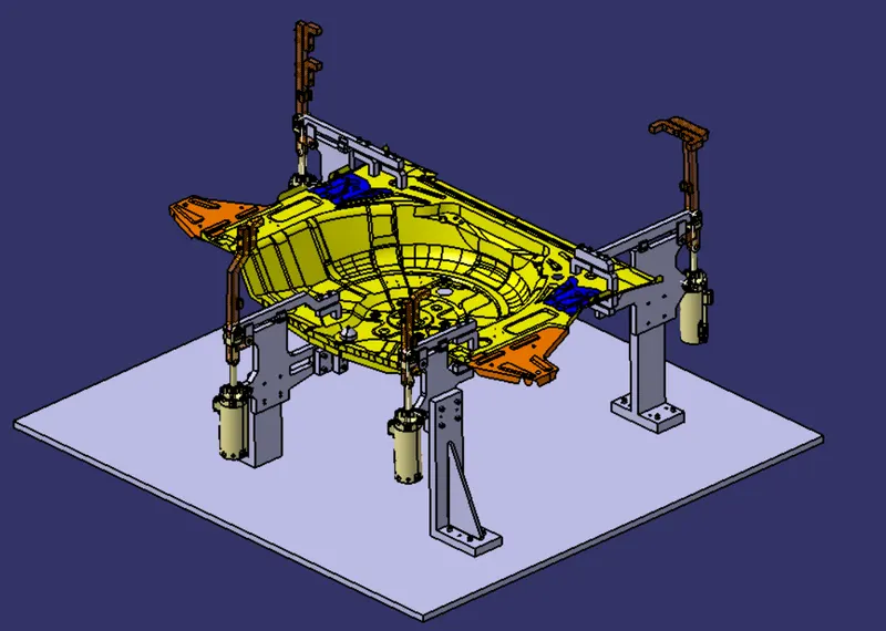
Parts of Clamp unit:
- Clamp Mylars : This part is in actual contact with the car panel as it hold or clamp the component.
- Rest mylar : This part also is in acrual contact with the car panel as car panel rest on this part.
- locks : Blocks can be machined in any desired shape according to the fixture. It is a normal shape of rectangle or square clock or L type shaped block.
- Shims or spacer : Shims or spacers are used to compensate for tolerance stack up. In pin unit, we need to control two directions that are C and Y using shims or space. Shims are generally thin sized plates used in group called shim pack and spacers are used as single plates and can be machined accordingly.
- Blade : blades are bolted on riser.
- Riser : The riser is used to increase the height of the fixture and it is a standard part.
321 Principle:
The 3-2-1 principle states that the six locators are sufficient to restrict the required degree of freedom of any workpiece. In this, motion is restricted using clamps and locators. A three-pin base can restrict five motions and six pins restrict nine motions.
A workpiece will be completely confined when blanked against:
- 3 points in one plane: The “3” in 3-2-1 refers to 3 locators (passive fixture elements) on the primary locating/datum surface.
- 2 points in another plane: The “2” in 3-2-1 refers to 2 locators on the secondary locating/datum surface.
- 1 point in a third plane: The “1” in 3-2-1 refers to 1 locator on the tertiary locating/datum surface
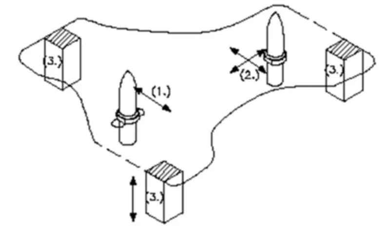
FORCE ACTING IN CLAMP & REST UNIT:
TO design a clamp unit we have considered some force that acts in the clamp for clamping purpose the force that act in clamp units are,
- Clamping force
- Holding force
Clamping force is not the same as holding force.
CLAMPING FORCE:
clamping force signifies the force applied to the workpiece by the drive mechanism via the clamp arm during the gripping or clamping operation.
Clamping force (Fs)= 48xS3 = force in newton HOLDING force
HOLDING FORCE:
holding force on the other hand denotes the maximum force, after locking the knee lever (over-center position) that can be applied by the workpiece on the workpiece on the gripper/ clamp arm without destroying the mechanism therefore particular attention the paid to the maximum holding force when for example during the production process (welding, bonding)there is a possibility of distortion of the component or if the clamp arm is used as a fixed stop.
If the holding force specified in the technical details is exceeded this will inevitably result in the destruction of the mechanism the clamp arm of the bearing position.
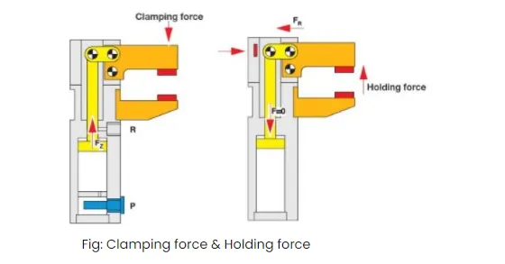
Clamp cylinder: Generally it is standard part.
Cylinder designation: In this unit we used clevis cylinder for clamping designation as CKG_1B_63_100Y
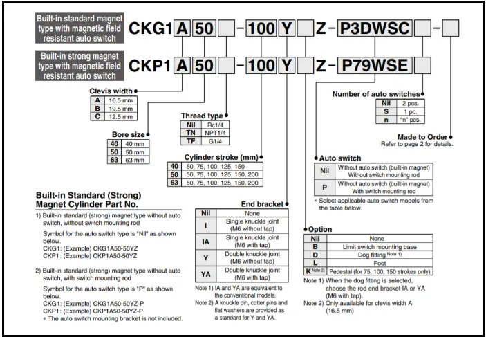
Nomenclature of cylinder as belows:
CKG1: Series of cylinder
B: Clevis width as 19.5 mm.
63: Bore size
100: Stroke of cylinder
Y: End bracket i.e. double knuckle joint (M6 without tap).
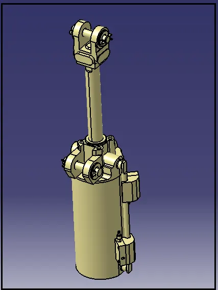
Procedure:
- First the neccesary file are downloaded such as car panel assembly.
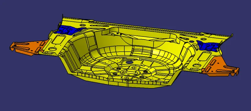
- The Clamp mylars and rest mylars are designed and positioned in such a way that the movement of the car panel is restricted. The Clamp Mylars are attached to the clamp arm for the opening and closing movement.
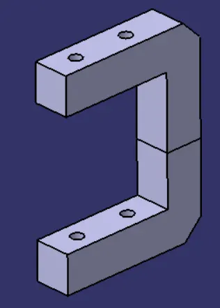
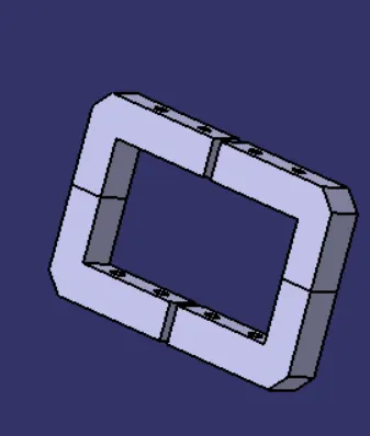
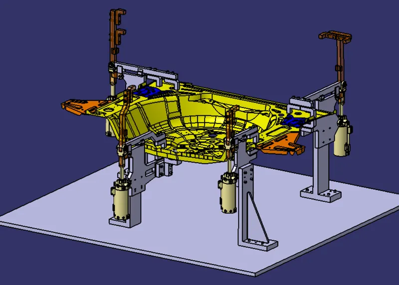
- Riser is a part on which all the parts are mounted and it is mounted on the base plate of the fixture. The risers are designed such that all the above parts are mounted on them. The risers are mounted to the base of the fixture
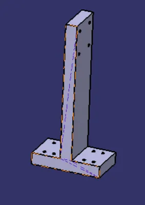
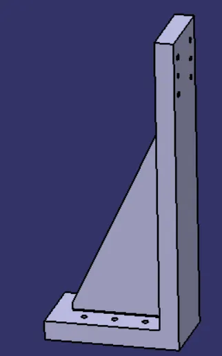
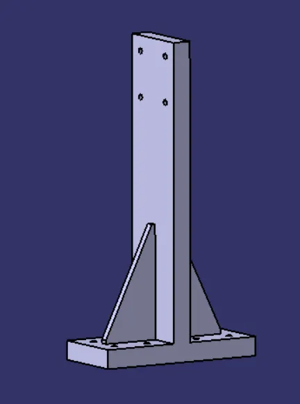
Now since there is change in the riser designs in all the above three,one of the important part Blades are attached to the riser in order to support the rest mylar, cylinder and the arm.
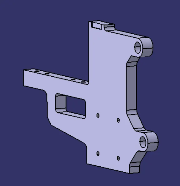
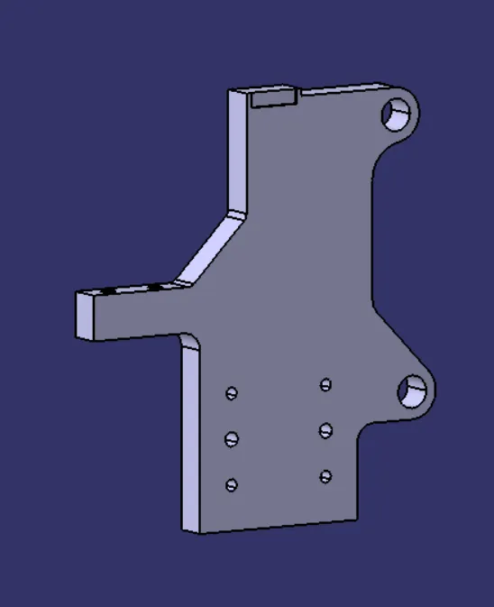
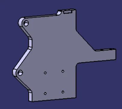
Shims are designed as per the required dimension witn constant thickness of 5mm.

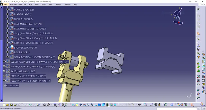
Stopper: The function of stopper is to restrict motion of clamp arm. It avoids clamp arm to rotate beyond limit. It has two parts male and female. The part attached to the arm is called as female part and part attached to the blade is called male part.
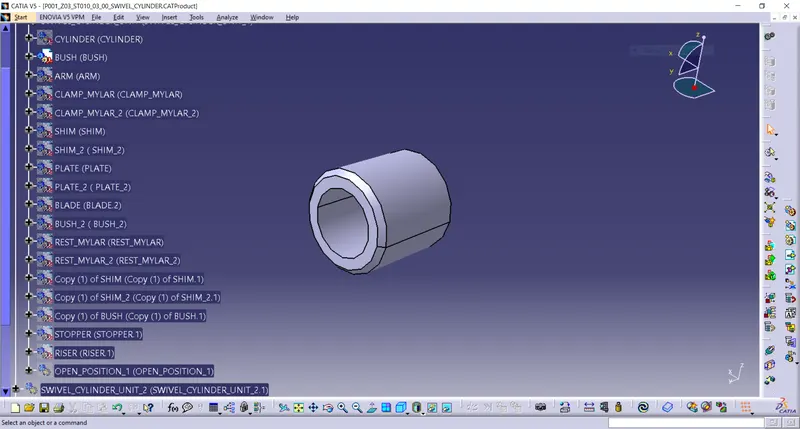
- Bush is friction type bearing. It is lubricated with grease, oil. It permits relative motion between two mating parts. It is made of hard material also its ID and OD are precisely machined or grinded. It is press fitted and after worn out is is replaced with new one instead of replacing other part which save cost. Mostly phosphor bronze or gun metal material used for making bush. In this unit three bhuses are used of same internal 12mm and 18mm external diameter but different length.
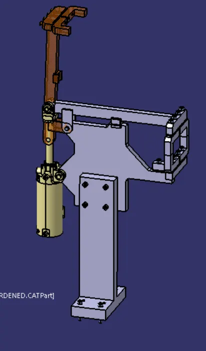
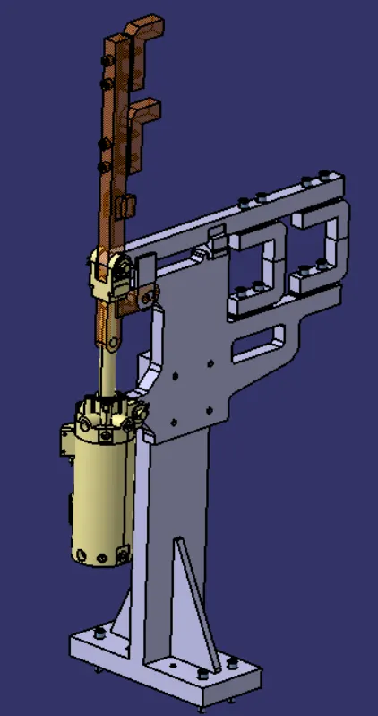
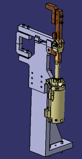
Now all the parts are assembly and the clamp units are positioned to hold the car panel as shown below. The coloured part of the arm represents the complete open position of the clamp arm.
One of the clamp unit is combined with the pin as shown below as required.
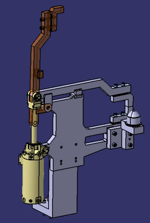
In this designthe hole diameter is 8mm simple as well as threaded. The hexagonal socket type head screw of diameter 8mm of required length wherever necessary.
Finally the all the risers are attached to the base plate with the help of bolts of appropriate size and dimensions (~8mm dia - threaded).
Conclusion:
Hence as per objective, the 3 different types of clamp unit with swivel cylinder & One clamp pin unit by considering holding force has been designed. Also the materials, surface finish & heat treatment used in the parts of clamp unit, purpose of clamp unit, (3-2-14 principle) achieved by clamping, PLP points (Principle Locating Points) are explanied.