Week 6 - CHT Analysis on a Graphics card
Objective :- To perform a steady-state conjugate heat transfer analysis on a model of a graphics card and study the effect of results by varying mesh combination.
Introduction :-
Generally, the GPU(Graphic Processing Unit) system (often call it graphic card) has heat sinks such as fins, cooling fan, and water cooler to decrease or maintain the their GPU chip temperature. However, as developing the technologies, integrated circuit of GPU chip has been increased. As a results, the conventional heat transfer based on conduction and convection has been limited. To maintain the GPU chip temperature, many microelectronic industries are investigated the thermal management and continous research is goin on.
Superb graphical and application performance enabled by the GPUs. These days GPU computing is quite well entrenched with many reported applications’ speedups ranging from 10X to 100X and higher. One of the practical issues that users face when using the n-core GPU workstations is the extraordinary power these systems consume and the heat that they produce.A combination of GPU compute model with an appropriate cooling technology has the potential to yield the most cost effective and energy-efficient model for operating data centers.
Solution :-
Geometry -
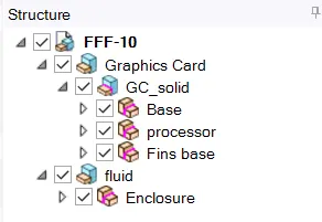
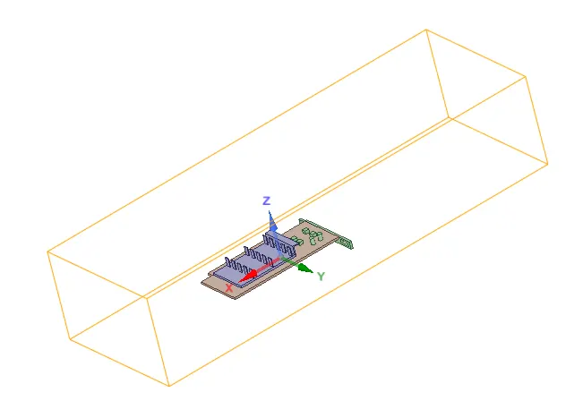
- Solid model (graphic card) is enclosed with fluid domain enclosure of appropriate size.
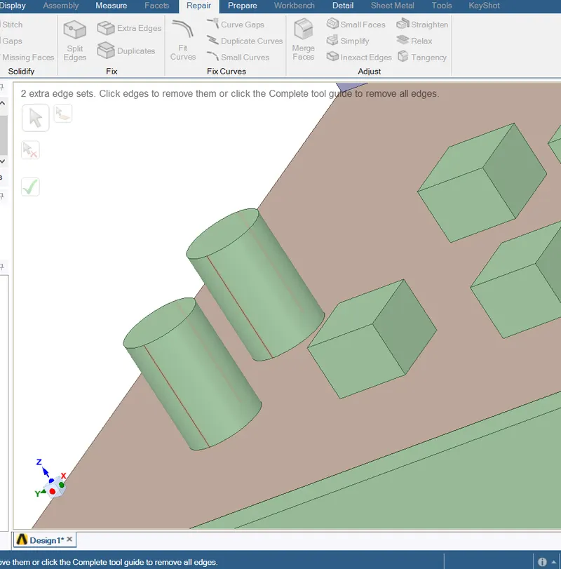
- Checked for extra edges & cleared in Space claim tool.
- In Workbench using overlap tool first all bodies are spereated to individual, if overlapping.
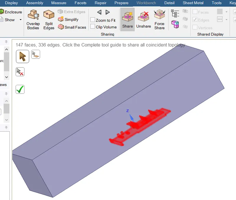
- Share prep is done/enabled for entire structure & thus topoplogy is shared b/w all bodies.
Meshing - Base line mesh
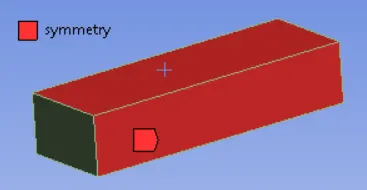
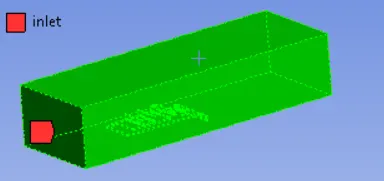
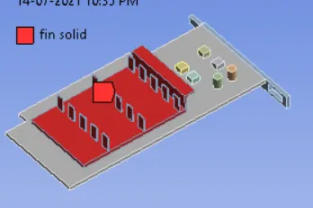
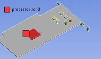
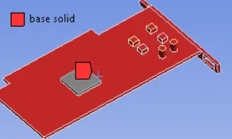
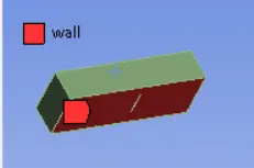
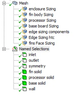
- Named selection is done accordingly. (pics attached)
- As defualt mesh is generated & then updated before moving to fluent.
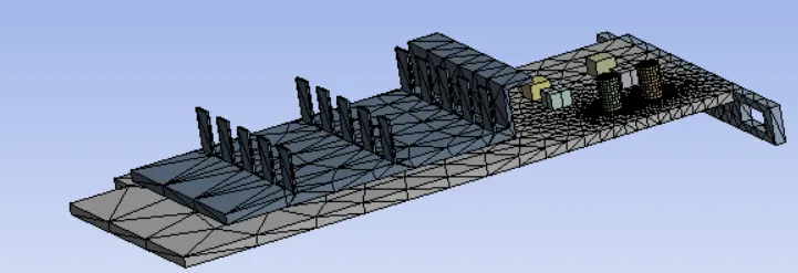
- Observed in a section plane that mesh at the interace b/w fluid to solid is shared evenly.

Fluent setup -
- Pressure based solver is selected,as velocities input in this setup are lesser than speed of sound Mach no. < 0.3.
- Problem was solved for steady state results,as we are intersted in the end thermal distribution & heat transfer rate.
- K-Omega SST viscous model is used to obtain accurate wall related heat transfer coefficient and Energy eqn is turned On.
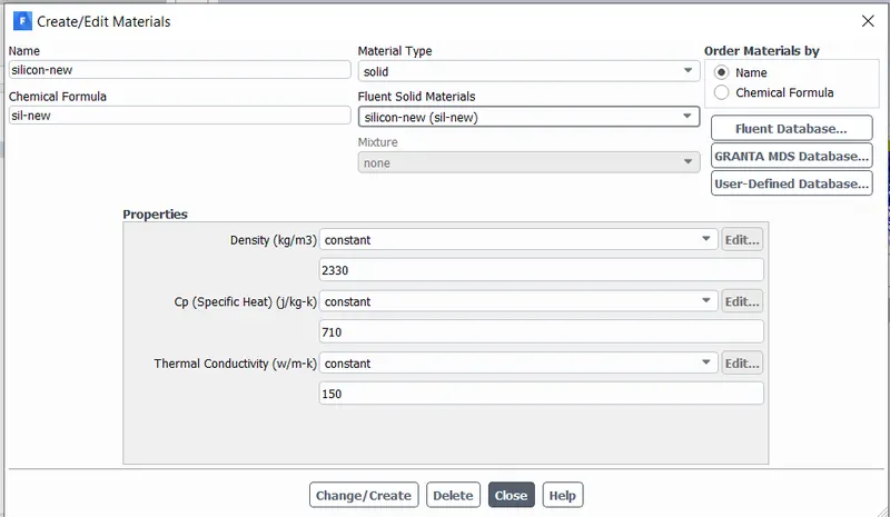
- Material was added to solid domain ,which are most commonly used in industrial application and Silicon properties are modified or changed, values are taken from Internet (https://www.americanelements.com/silicon-wafer-7440-21-3)
- Silicon (wafer) = Processor
- Steel = Base board
- Aluminium = Fins & its base.
- In cell-zone solid parts appropriate materials are applied.
- Computing power is growing & brought up many divices which are small & does greater calculations.Their are researches is going on Nonotechnology, where the size very small & thermal management is challenging.
- Proccesor is underneath the fins & Base support,which heats up a lot, fins help to dissipate heat & maintain safe temperature.
- For CHT analysis the main heat generation source term is appied to processor.
- Let the syetem power fo graphic card be 10W (found in most) & net volume of processor is 64e-9m^3
Heat generated = Power / Volume = `10/(64e^-9)`= `15.625 e^-8 (W/(m-k ))` 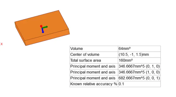
- The above constant value is added in Silicon processor by enabling source term in cell zone condition
- Under fluid cell zone 'Air' same as default considered.
- For boundary condition Inlet is velocity are changed into three different values(1,2.5 & 5m/s) in this analysis.Outlet is pressure type = 0 pa.
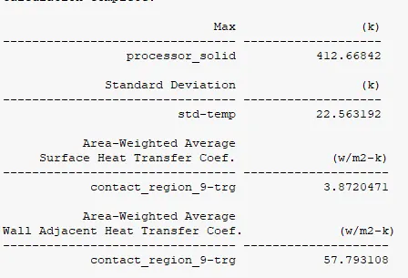
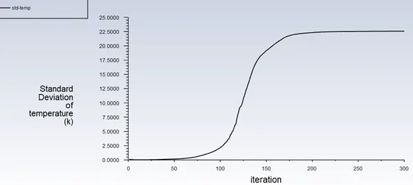
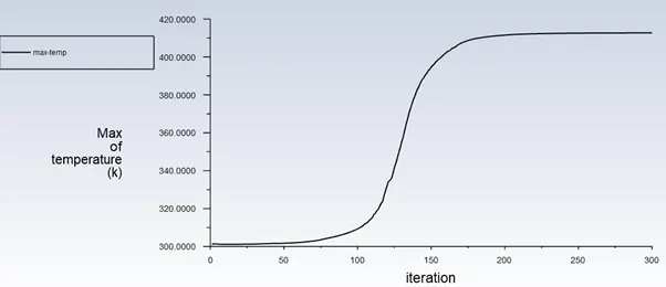
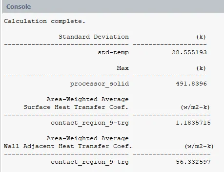
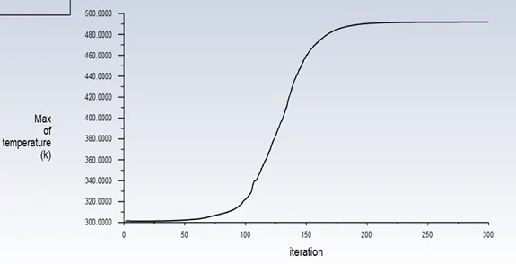
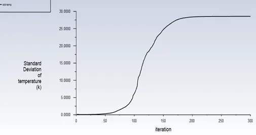
- Report difinitions are added to obtain plots of Maximum temperature in volume integral & standard deviation of temperature in Card.
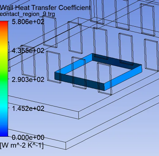
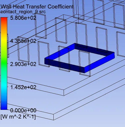
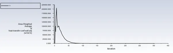
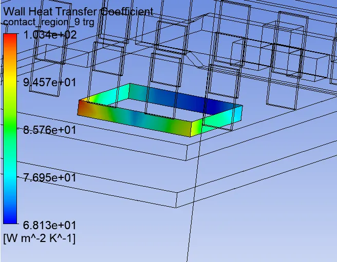
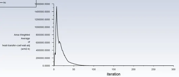
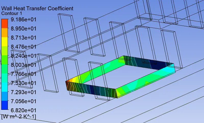
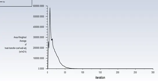
- In surface integrals report under wall fluxes wall adj. HTC plot is recorded.The Lateral surface of proccesor is subjected to convection heat transfer, therefore HTC is calculated along this area
- Further solution was Hybrid Intialized.
- Coupled Scheme was used as default suggested by fluent and around 300-500 iterations are Run in each cases.
Results -
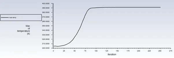
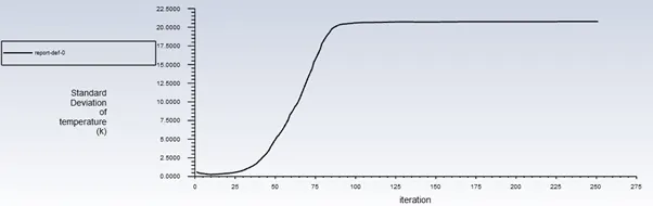
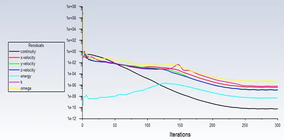
- After 175 iterations residuals converged and at 75 iterations devialtion of temperature in graphic card remained constant.
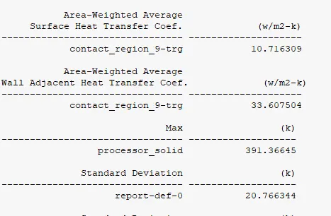
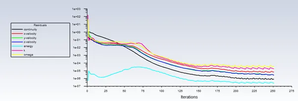
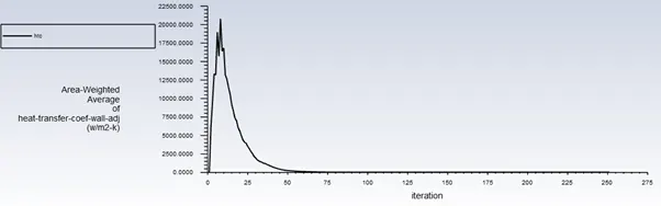
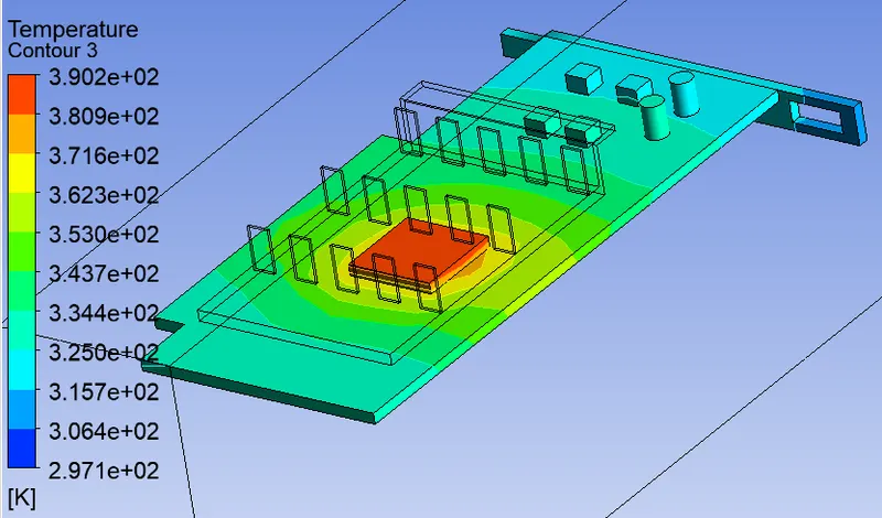
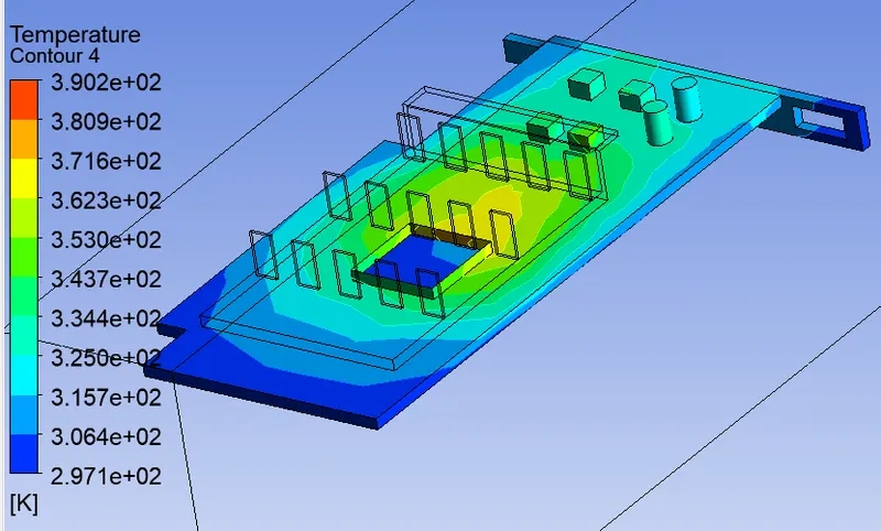
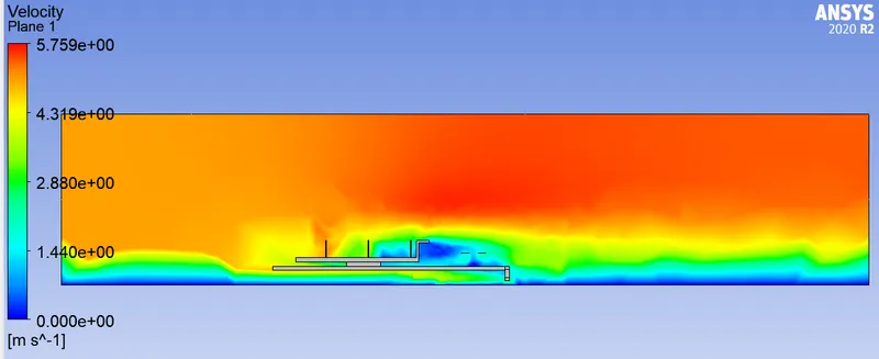
Refined Mesh cases
BC Inlet Velocity = 5m/s
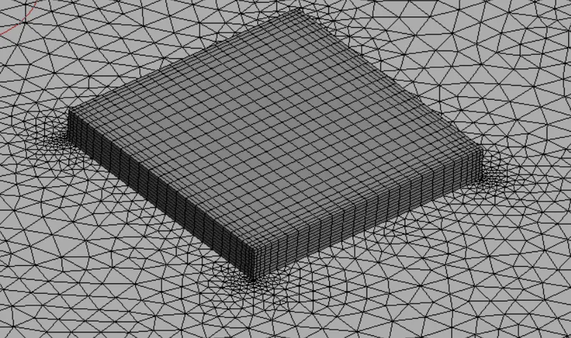
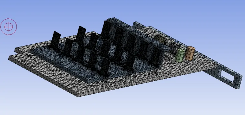
Different sizing of Mesh is done for all parts, fine mesh is applied for Processor & fins in order to obtain good simulation results of conduction & convection. This produced a combination of Tetra,Hexa,Wedge & pyramid shape meshes.
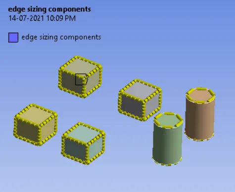
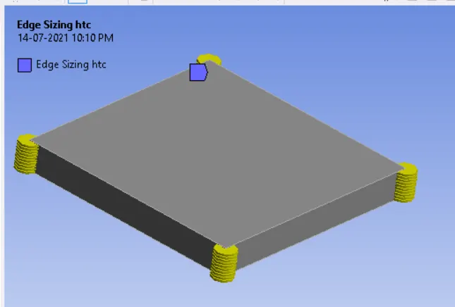
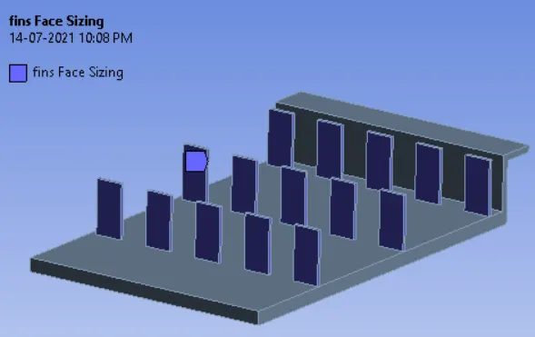
Different cases are created with varying mesh sizes to check the effect of mesh setting on the results.
| Element sizing in mm | Results | |||||||||||
| Enclosure body |
Fins face | Fin base body |
Base Board body |
Processor body |
Processor lateral edges | components edge sizing |
Total no. of elements |
wall adj. HTC (w/m2-k) |
Surface HTC (w/m2-k) |
Max. Temp.(k) |
Std. Deviation(k) |
|
| case 1a | 8 | 0.8 | 2 | 2 | 1 | 5 | 5 | 57300 | 27.99 | 9.022 | 389.53 | 25.39 |
| case 1b | 5 | 0.5 | 1 | 1 | 0.6 | 8 | 6 | 119207 | 37.45 | 11.75 | 388.23 | 25.01 |
| case 1c | 3 | 0.2 | 0.8 | 1 | 0.4 | 10 | 6 | 340770 | 52.53 | 10.85 | 383.41 | 19.61 |
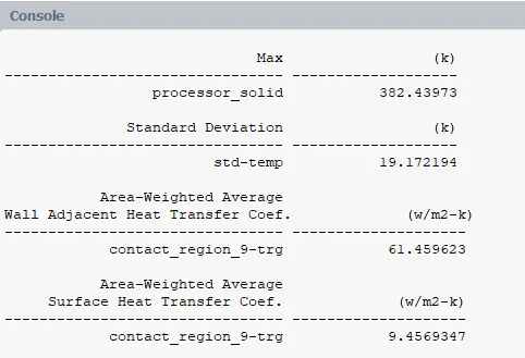
| case 1d | 2 | 0.2 | 0.8 | 1 | 0.4 | 10 | 6 | 718077 | 61.45 | 9.45 | 382.43 | 19.17 |
From the above it is clear that as when mesh size of enclosure is reduced a Wall Adj. HTC values is increasing, thus it is directly dependent on Mesh parameter at first layer or boundaries to yeild in accurate results.
Considering above study on Mesh case 1d - highly refined mesh is used for further anlysis cases on varying velocities.
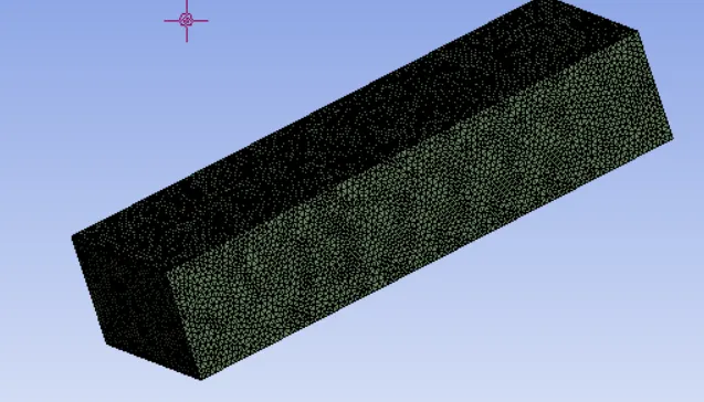
Case 1(d) - Mesh view
Boundary condidtion : Inlet velocity = 5m/s
Results
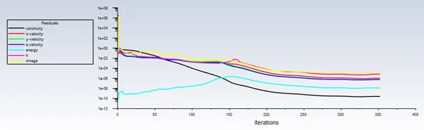
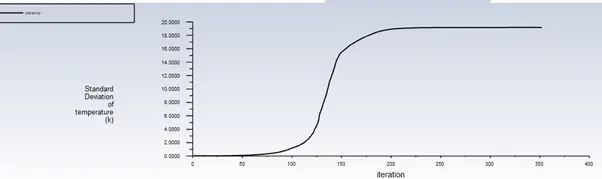
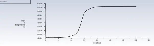
- After 200 iterations residuals converged and at 150 iterations devialtion of temperature in graphic card remained constant.
- Due to higher velocity heat is drawn quickly from the solid components & it is evident that Temp. deviation attained constant earlier.
 \
\
Case -2 :-
Boundary condidtion : Inlet velocity = 2.5m/s
Results -
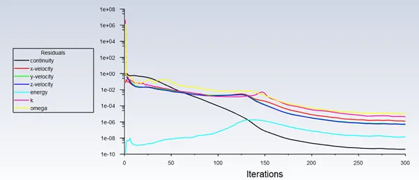
- After 250 iterations residuals converged and at 175 iterations devialtion of temperature in graphic card remained constant.
Case -3 :-
Boundary condidtion : Inlet velocity = 1m/s
Results -
- After 250 iterations residuals converged and at 175 iterations devialtion of temperature in graphic card remained constant.
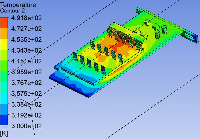
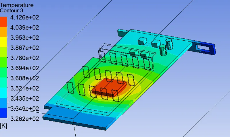
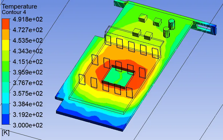
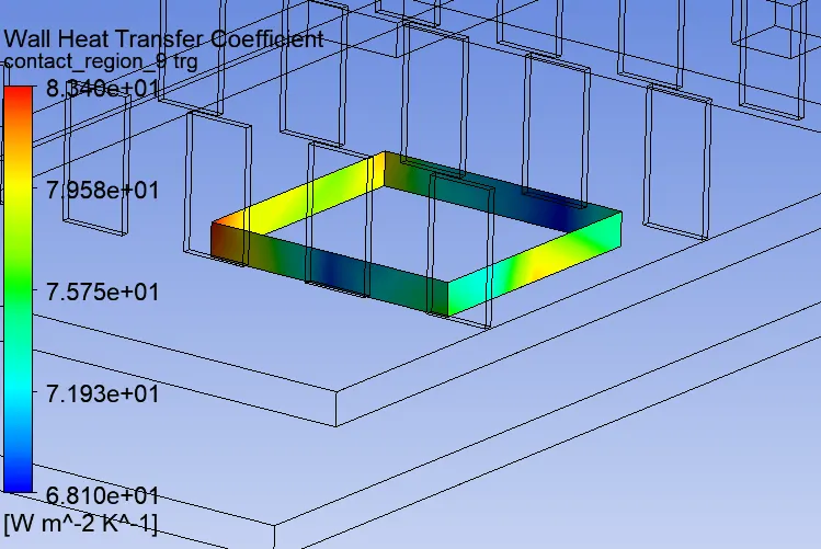
Potential Hotspot region :
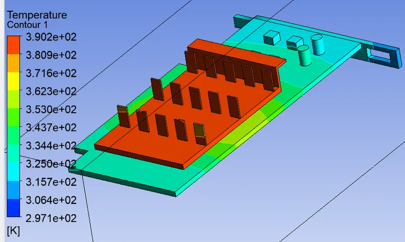
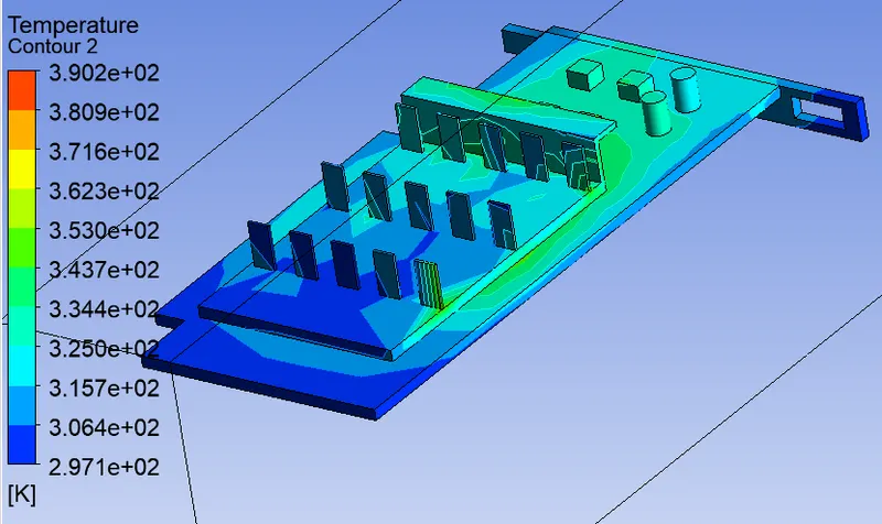
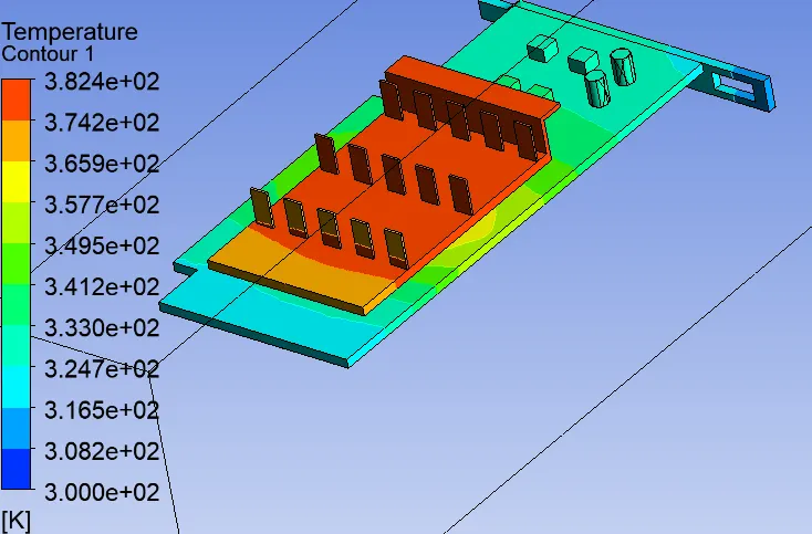
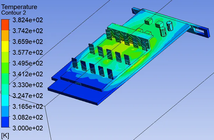
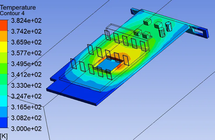
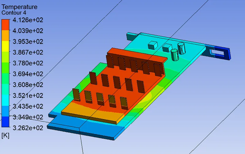
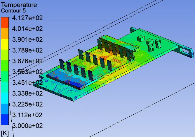
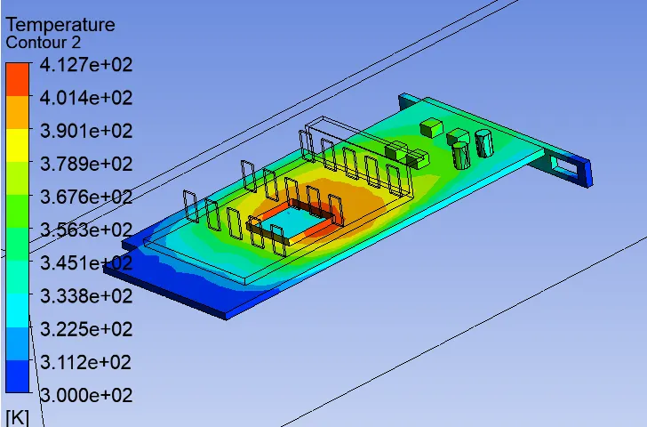
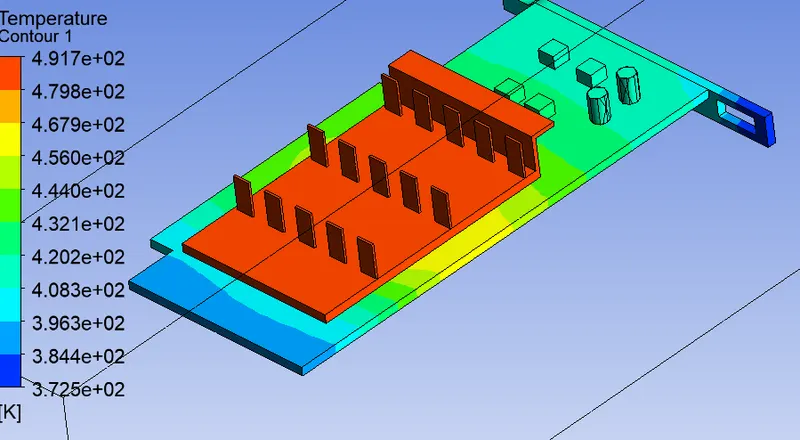
- Fins that are near to Inlet side are less in temperature due to first fluid interaction, thus good heat transfer.Whereas fins that are behind interacts with bit hot fluid.
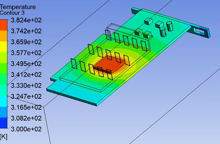
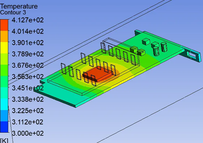
- Fins that are near to processor are high in temperature and thus accomodate more heat as processor continously generates.
- At base board there is hotspot point just below the region of processor & as distance increases temperature reduces.
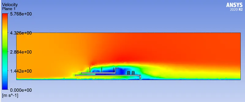
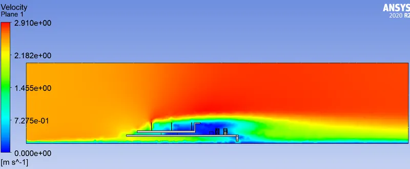
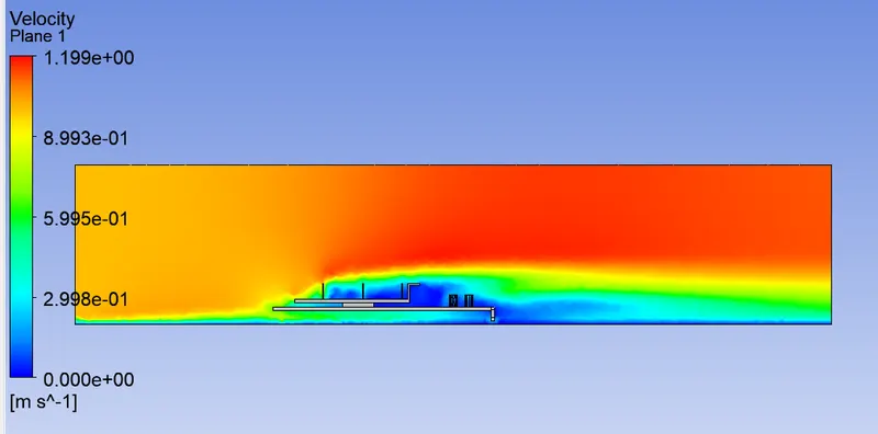
- Behind the fin base support higher temperature is clearly observed due to the blunt shape , when air passes it creates a vortex region low pressure region thus there is insufficent convection heat transfer.