Week 6 - CHT Analysis on a Graphics card
AIM:
CHT Analysis on a Graphics card
Theory:
The Graphic card is responsible for rendering an image to your monitor, and it does this by converting data into a signal your monitor can understand. The better your Graphic card the better and smoother an image can be produced.
in graphic card heat is generated in the processor because processor run electricity so when the currrent is flowing through the processor, it has some resistance so due to this heat is generated. to reduce the temperature of processor, fins are attached to processor so it can work efficiently and increase its life span. the material used for maling processor are copper, silica. fins are most commonly used in heat exchanging devices and the material used for making of fins are aluminium. the base on which processor,power connectors are placed and the base is made up of steel. so here we are going to simulate on the conjugate geat transfer analysis on the graphic card
brief description of why and where a CHT analysis is used:
Conjugate heat transfer corresponds with the combination of heat transfer in solids and heat transfer in fluids. In solids, conduction often dominates whereas in fluids, convection usually dominates. Conjugate heat transfer is observed in many situations. For example, heat sinks are optimized to combine heat transfer by conduction in the heat sink with the convection in the surrounding fluid. The temperature field and the heat flux are continuous at the fluid/solid interface. However, the temperature field can rapidly vary in a fluid in motion: close to the solid, the fluid temperature is close to the solid temperature, and far from the interface, the fluid temperature is close to the inlet or ambient fluid temperature. The distance where the fluid temperature varies from the solid temperature to the fluid bulk temperature is called the thermal boundary layer. The thermal boundary layer size and the momentum boundary layer relative size is reflected by the Prandtl number.
Prandtl number = `(C_p . mu)/K`
where `C_p` is heat capacity at constant pressure (SI unit: J/kg.K)
`mu`is the absolute visosity (SI unit: NS/m^2)
K is the thermal conductivity (SI unit: W/m.k)
for the Prandtl number to equal 1, thermal and momentum boundary layer thicknesses need to be the same. A thicker momentum layer would result in a Prandtl number larger than 1. Conversely, a Prandtl number smaller than 1 would indicate that the momentum boundary layer is thinner than the thermal boundary layer. The Prandtl number for air at atmospheric pressure and at 20°C is 0.7. That is because for air, the momentum and thermal boundary layer have similar size, while the momentum boundary layer is slightly thinner than the thermal boundary layer. higher the thermal boundary layer, there will br higher the heat transfer from fluid to solid.
Geometry of Graphics card:
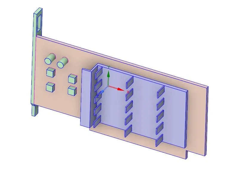
the above figure represents the graphic card in which we are going to simulate the conjugate heat transfer analysis.
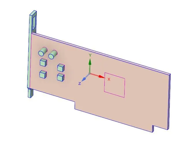
Base- Fins-
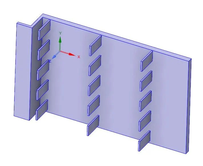
Processor- Enclosure-
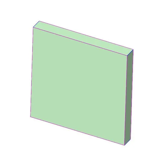
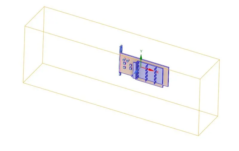
on the graphic card i have provided an enclosure because in which the fluid flow over the graphic card.
Mesh:
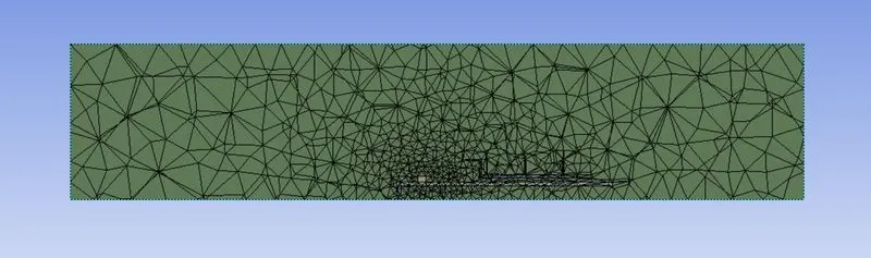
i have created a baseline mesh. i have named the rightside face of the enclosure as inlet and leftside face of enclosure as outlet. the remaining faces of enclosure are named as symmetry. the total number of elements created in the mesh are 84010.
Setup:
pressure based solver is used here with steady state process is used. the fluid i am going to use here is air. the k-omega SST turbulance model is used and also i have enabled energy equation.
selection of materials-
base - steel (type solid)
fins - aluminium (type solid)
processor - copper (type solid)
fluid - air (type air)
these materials are selected in the fluent at the cell zones.
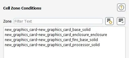
open each component and select the material of component. as we know that processor is heat soursing element. generally the power consumption of processor is 60 to 120W. here i have taken the pr0cessor with 75w. so that i have enabled the sourse term in the procssor which is present in the cell zones.
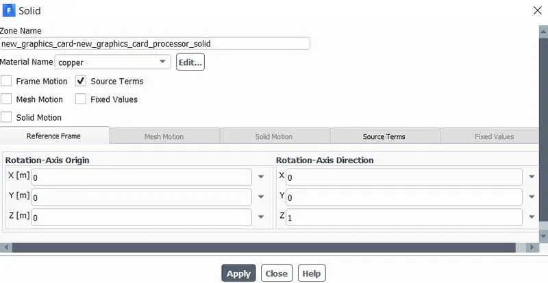
here we are going to see a new term volumetric heat sourse. volumetric heat sourse is the energy released in a unit volume at unit second. the energy relased from processor is the power consumpted by the processor, that is the energy relased from the processor is 75w. the dimensions of processor is 8*8*1 mm^3 and the length of the graphic card is 56mm
so the final volumetric heat sourse is 75/(8*8*1) W/mm^3 = 1171875000 W/m^3.
the inlet velocity of fluid is 1m/s and the inlet temperature of the fluid is 300k. i have created the area weighted average of heat transfer coefficent attained by processor. coupled solution method is used here and the standard initialization. after the initialization, we have to create temperature contour on graphics card.
solution:
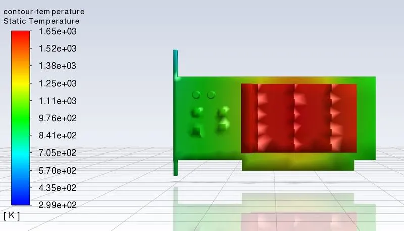
temperature contour on graphic card-
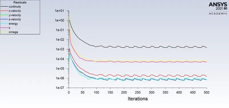
residual plot-
- the maximum heat transfer coefficent attained by processor is -325.8100W/(m^2 K)
- the maximum temperature attained by processor is 1660.1022 K
Result:
temperature contour on base and processor-
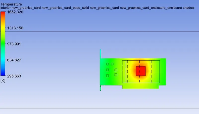
the potential hotspots(that is the region where the max. temperature is present)are identified at the processor.
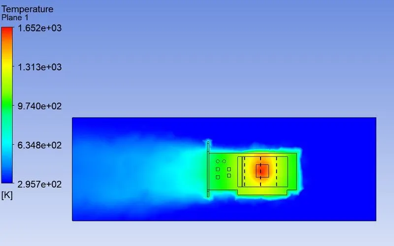
temperature plane along the flow-
velocity plane along the flow-
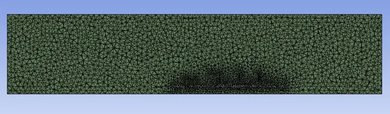
refined mesh:
the element size of the outer enclosure is 2.5mm. by using body sizing tool , the element size of the graphic card is taken as 1mm.therefore total number of elements obtained is 396788.
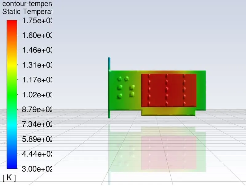
solution:
temperature contour on graphic card-
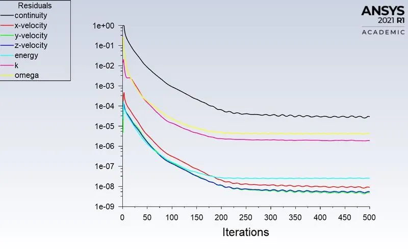
residuals plot-
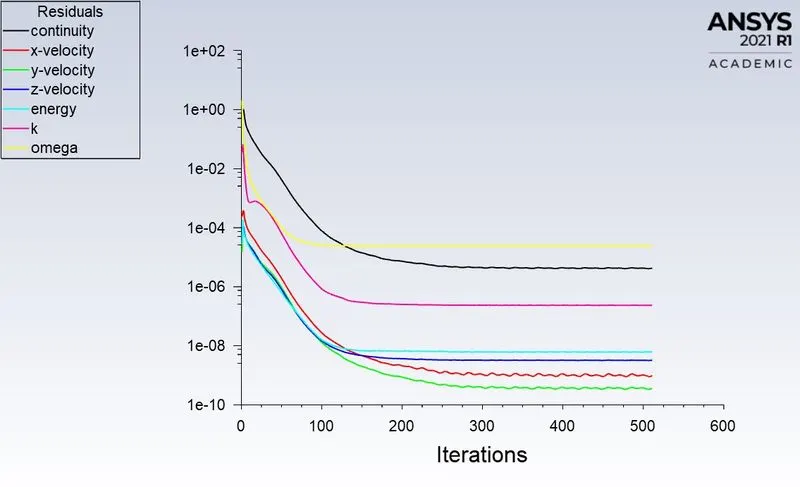
- the maximum heat transfer coefficent attained by processor is -165.18249 W/(m^2 K)
- the maximum temperature attained by processor is 1747.9795 K
Result:
temperature contour on base and processor-
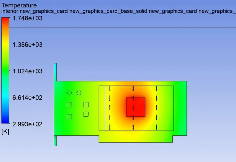
the potential hotspots(that is the region where the max. temperature is present)are identified at the processor.
temperature plane along the flow-
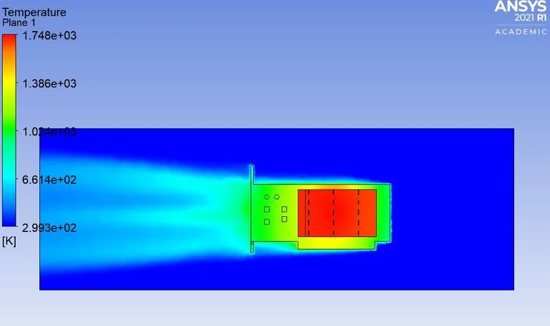
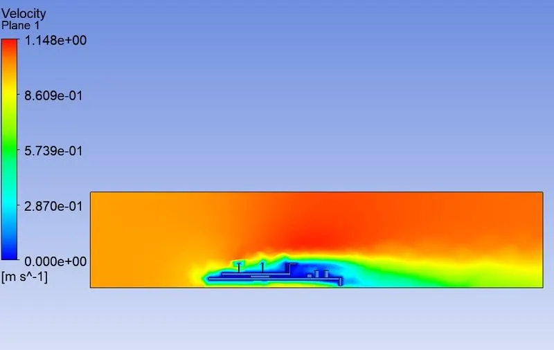
velocity plane along the flow-
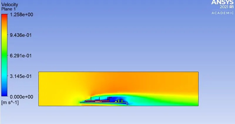
by refining the mesh size we can clearly visusalize the primitive variables at each cell and refinement of cell size increased the accuracy of solution.
for v = 3m/s
with the same refined mesh and the same setup as mesntioned above with inlet velocity of fluid 3 m/s.
solution:
residuals plot-
temperature contour on graphic card-
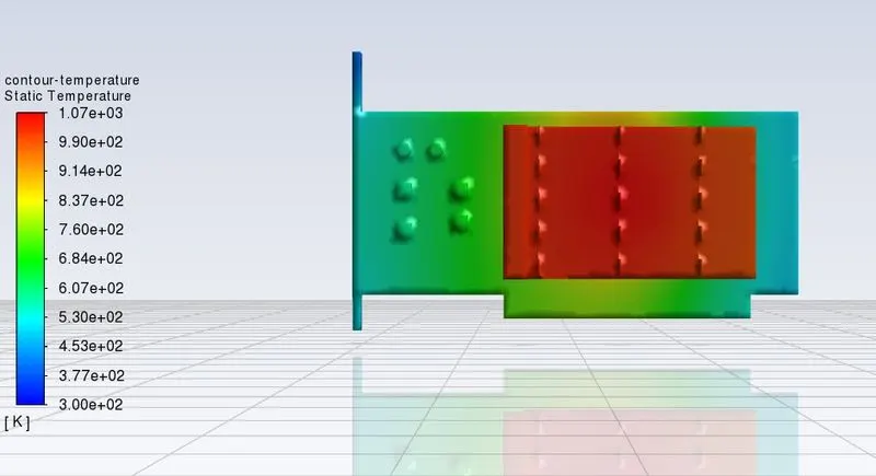
- heat transfer coefficent attained by processor is -319.47917 W/(m^2 K)
- temperature attained by processor is 1067.4264 K
result:
temperature contour on base and processor-
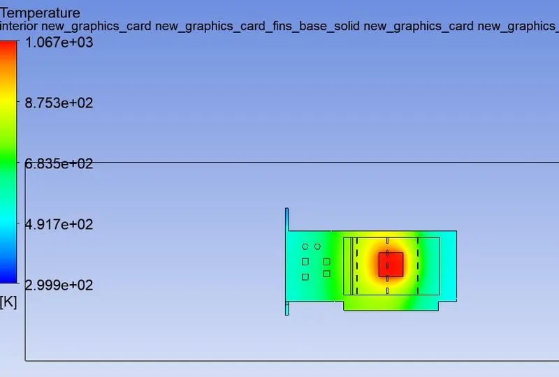
the potential hotspots(that is the region where the max. temperature is present)are identified at the processor.
temperature plane along the flow-
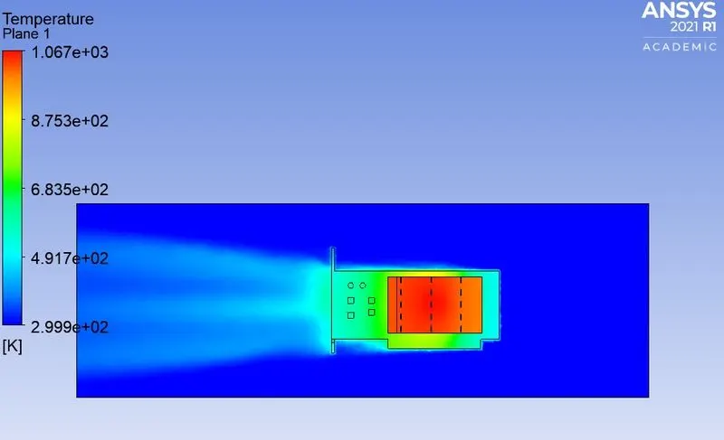
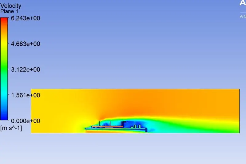
velocity plane along the flow-
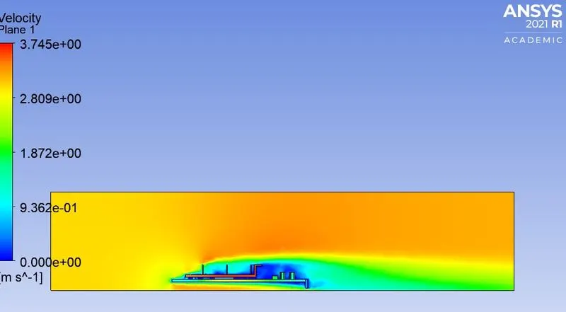
for v = 5 m/s
the refined mesh and setup are same as mentioned above , here the velocity of fluid at inlet is 5 m/s
solution:
residuals plot-
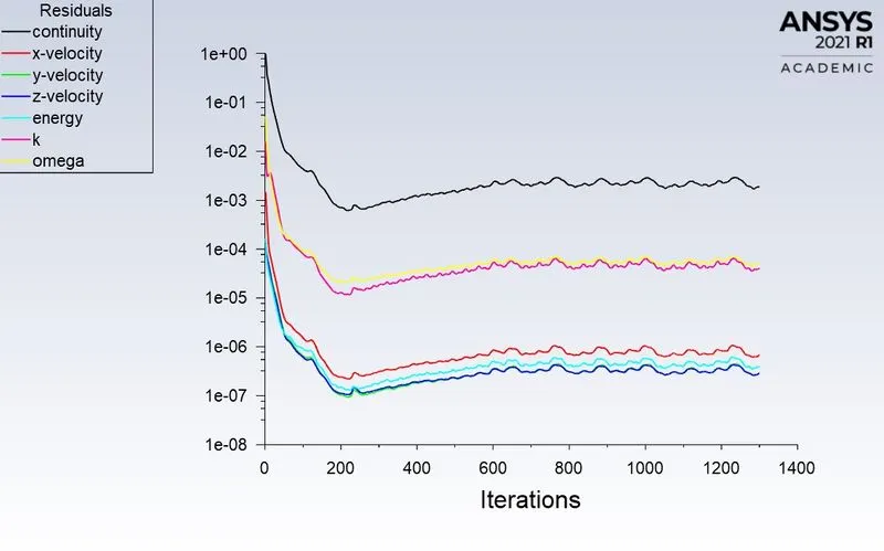
temperature contour on graphic card-
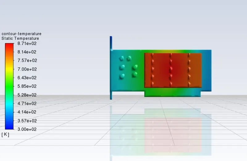
- heat transfer coefficent attained by processor is -435.01908 W/(m^2 K)
- temperature attained by processor is 871.20263 K
result:
temperature contour on base and processor-
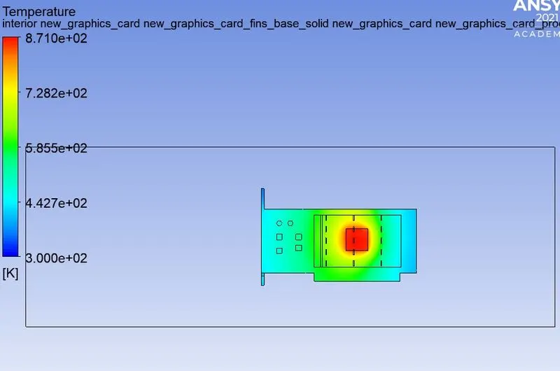
the potential hotspots(that is the region where the max. temperature is present)are identified at the processor.
temperature plane along the flow-
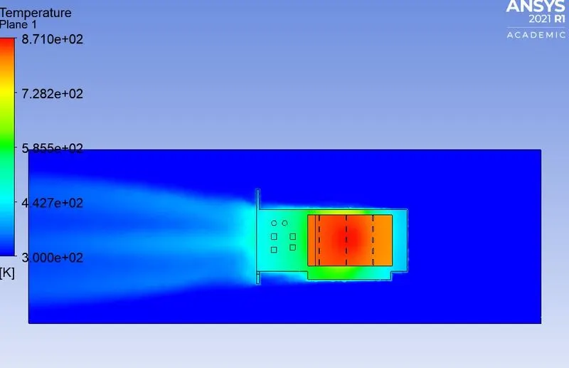
velocity plane along the flow-
observations:
| velocity(m/s) | surface heat transfer coefficent at processor W/(m^2 K) | max. temperature at processor K |
| 1 | -165.182 | 1747.9795 |
| 3 | -319.479 | 1067.426 |
| 5 | -435.019 | 871.202 |
by taking the velocities of fluid at inlet as 1,2,3 m/s the maximum temperature of the processor gets reduced with increasing of surface heat transfer coefficent with each velocity.