Week 6 - CHT Analysis on a Graphics card
Aim: CHT analysis of graphic card.
Theory:
Conjuagate heat transfer reffers to combination of heat transfer in solids and fluids due to themal interactions between solid and fluid. In solids conduction often dominates whereas in case of liquids convection dominates. Conjugate heat transfer is observed in many situations. For example, heat sinks are optimized to combine heat transfer by conduction in the heat sink with the convection in the surrounding fluid, shell and tube heat exchanger, water cooler, graphic card of laptop/desktop etc.
In the current project CHT analysis of graphic card is carried out for different velocities of air and maximum temeperature in the graphic card, locations of maximum temperature is studied.
Geometry
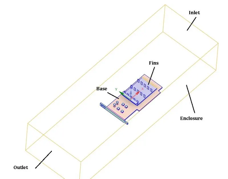
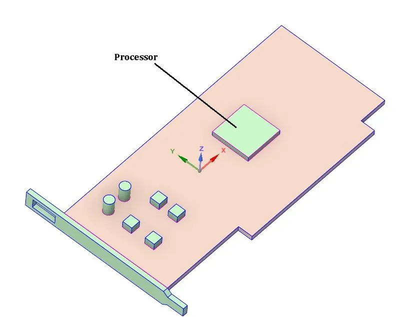
Mesh
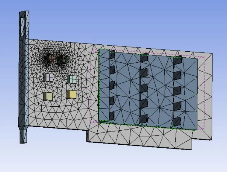
While meshing share topology option is enabled so that mesh is conformal mesh (as shown below), which allows to transfer heat from one component to another component.
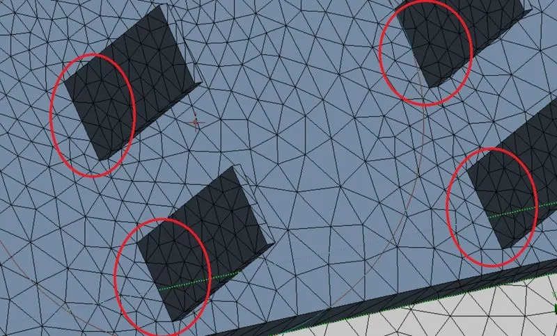
a) Baseline mesh (No. of elements 83647)
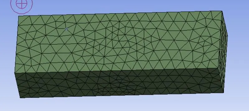
b) Refined mesh (302130)
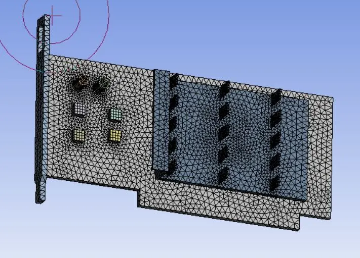
Simulation is performed for baseline mesh and refined mesh. For baseline mesh inlet velocity is taken as 5 m/sec and temperature of inlet air is taken as 300K.
As fas as refined mesh simulation is concerned, simulation is carried for 3 velocities i.e. 5 m/sec, 3 m/sec and 1 m/sec. Agian temperature of inlet air is taken as 300K.
Simulation settings
Solver type: Pressure based
Steady state simulation
Viscous model: k-omega
Materials used: Base-Aluminium, Fin-Copper, Processor-Silicon, Fluid-Air
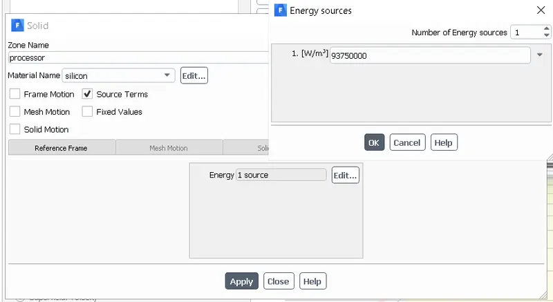
Now, if power supplied to core, P is 6 watt. Volume (V) of processor is 64 m^3. Hence volumetric heat generation = P/V = 93750000 w/m^3. Hence in processor 93750000 heat is getting generated, which is set as source of heat for processor.
Boundary conditions: Inlet-Velocity inlet, Outlet-pressure outletm, Bottom wall of enclosure-wall and top, left and right side of enclosure- symmetry
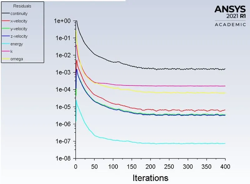
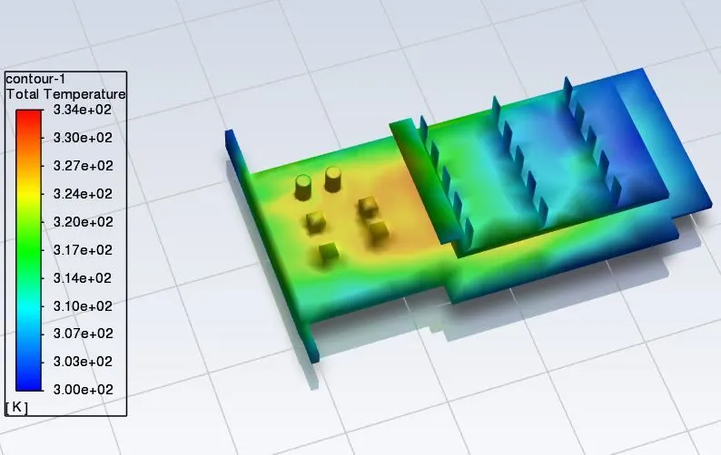
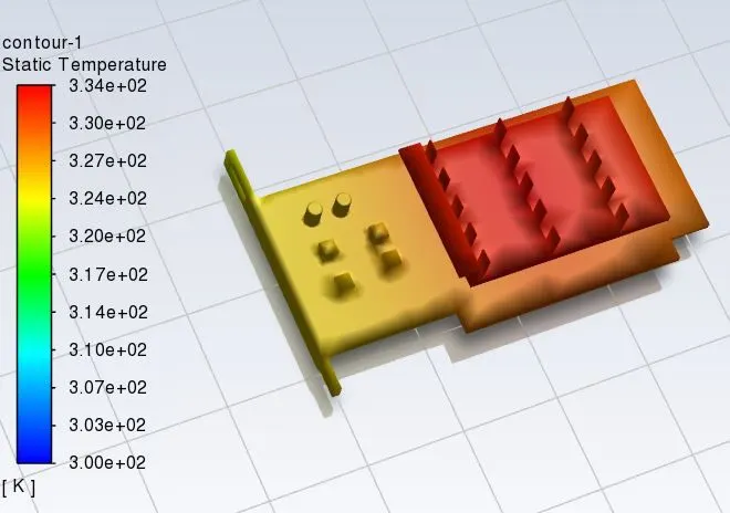
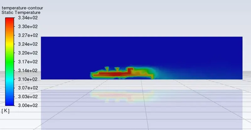
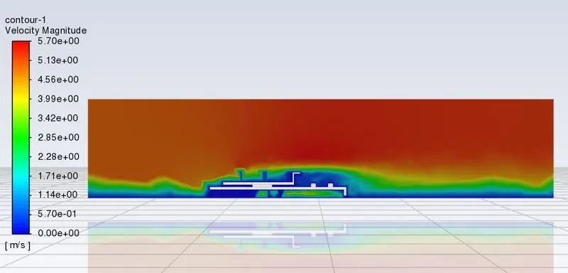
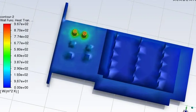
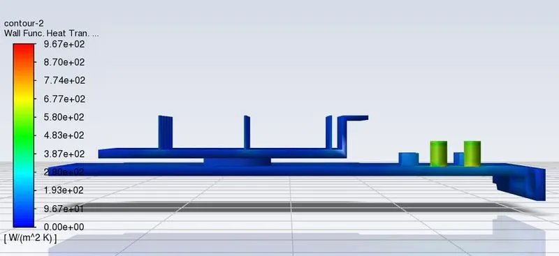
Baseline simulation (inlet velocity 5 m/sec)
Refined mesh simulation
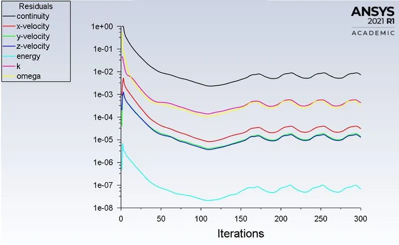
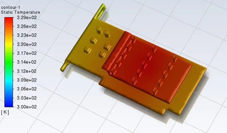
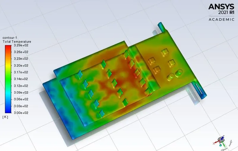
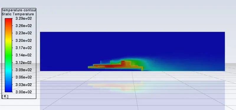
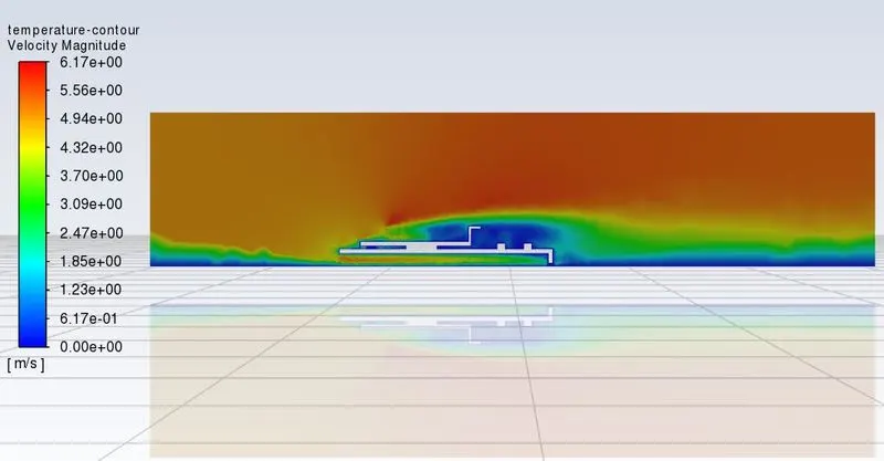
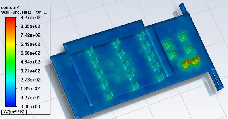
a) Inlet velocity 5 m/sec
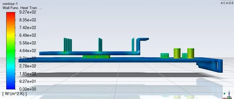
b) Inlet velocity 3 m/sec
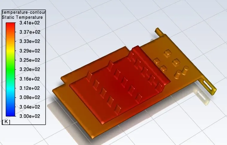
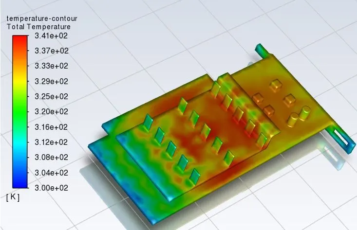
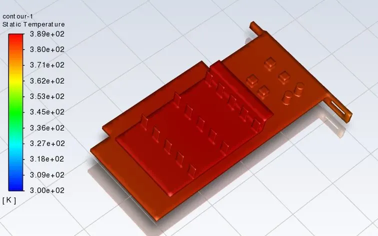
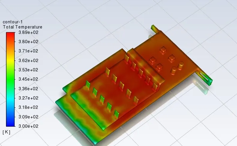
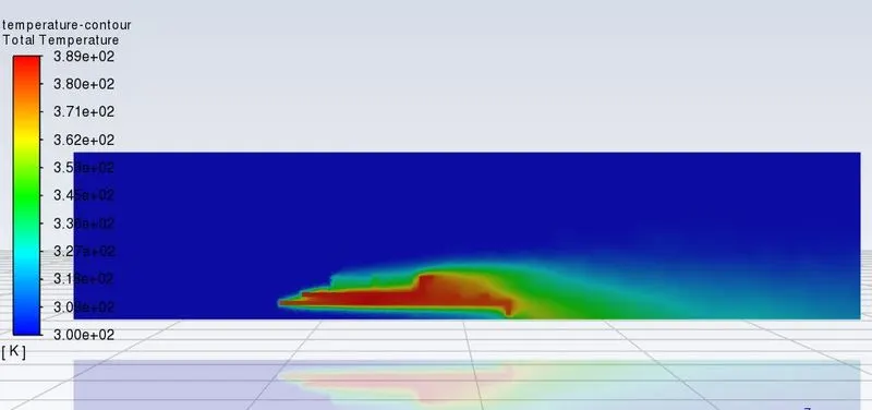
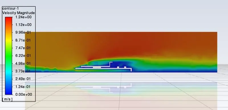
c) Inlet velocity 1 m/sec
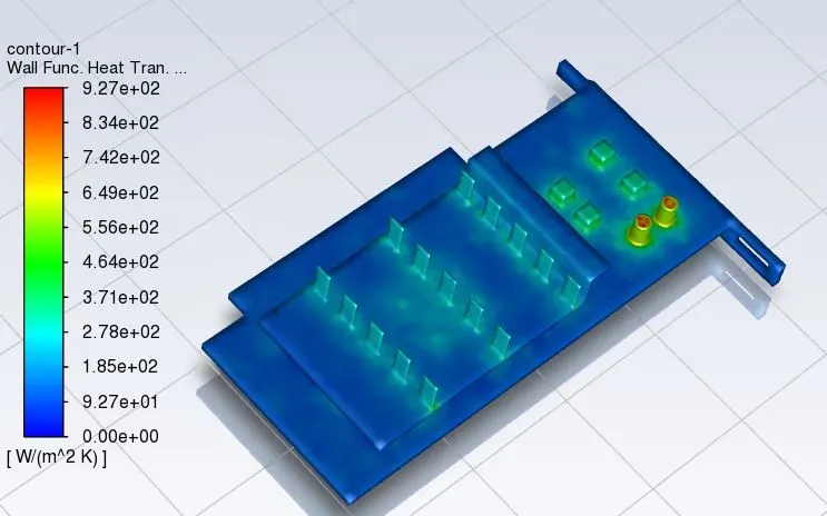
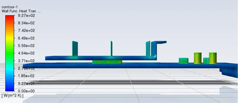
Results and discussion
Simulation is run for baseline mesh with inlet velocity of 5 m/sec and for refined mesh with with inlet velocity of 1, 3 and 5 m/sec.
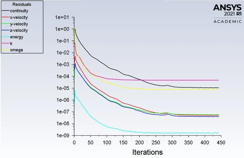
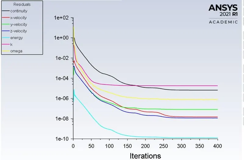
In all cases solution is converged as nature of residual plot is of same after certain no. of iterations.
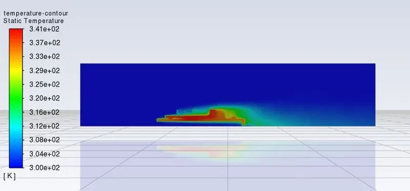
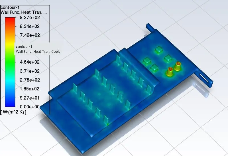
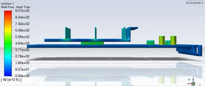
In the graphic card, processor and fins are regions which has maximum temperature.
Results for refined mesh
| Sr. No | Inlet velocity (m/sec) | Max. temperature attained (K) |
| 1 | 1 | 389 |
| 2 | 3 | 341 |
| 3 | 5 | 329 |
Results for baseline mesh
| Sr. No | Inlet velocity (m/sec) | Max. temperature attained (K) |
| 1 | 5 | 334 |
From above results we can say that, with incresed in inlet air velocity, the maximum temperature attained is less which is because, with incresed in inlet velocity rate of heat transfer by convection increases. Also for baseline simulation with inlet velocity 5 m/sec, maximum temperature is 334 K only, which is differing from refined mesh due to mesh element size.