Week 6 - CHT Analysis on a Graphics card
Objectives:
1. Run the simulation by varying the velocity from 1m/sec to 5m/sec for at least 3 velocities and discuss the results.
Here 3 velocities selected are as
CASE 1 -1 m/sec
CASE 2 -3 m/sec
CASE 3 - 5 m/sec
Geometry Setup
Given model is opened in Spaceclaom
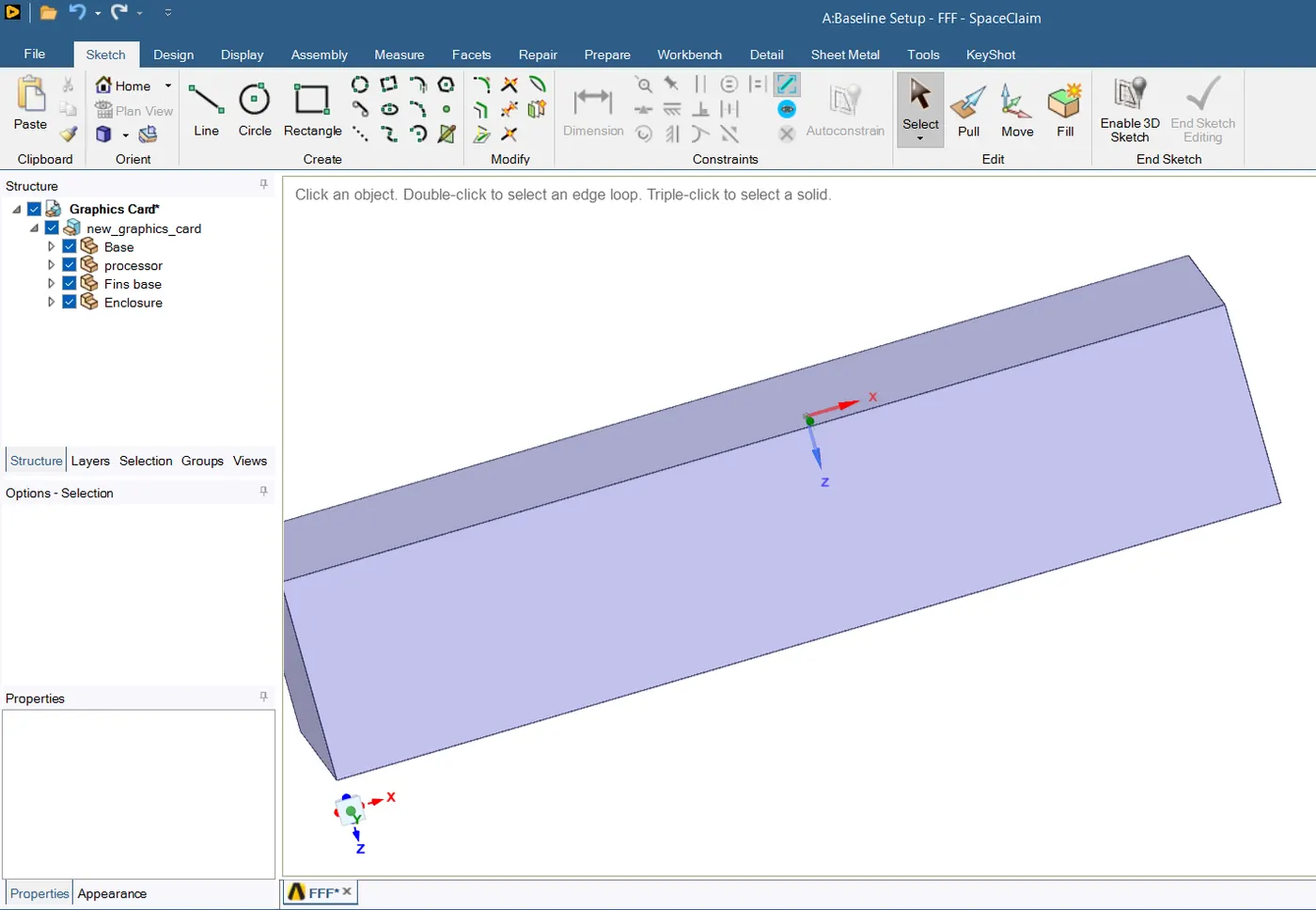
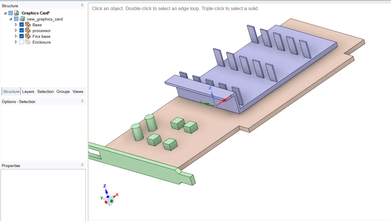
Various parts of the gepometry are as follow
- Base
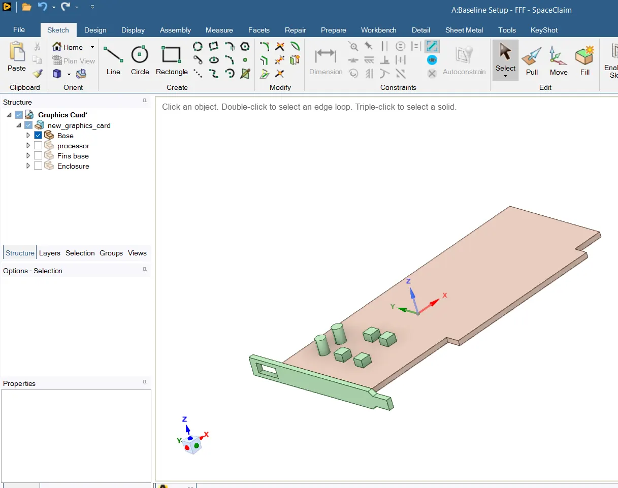
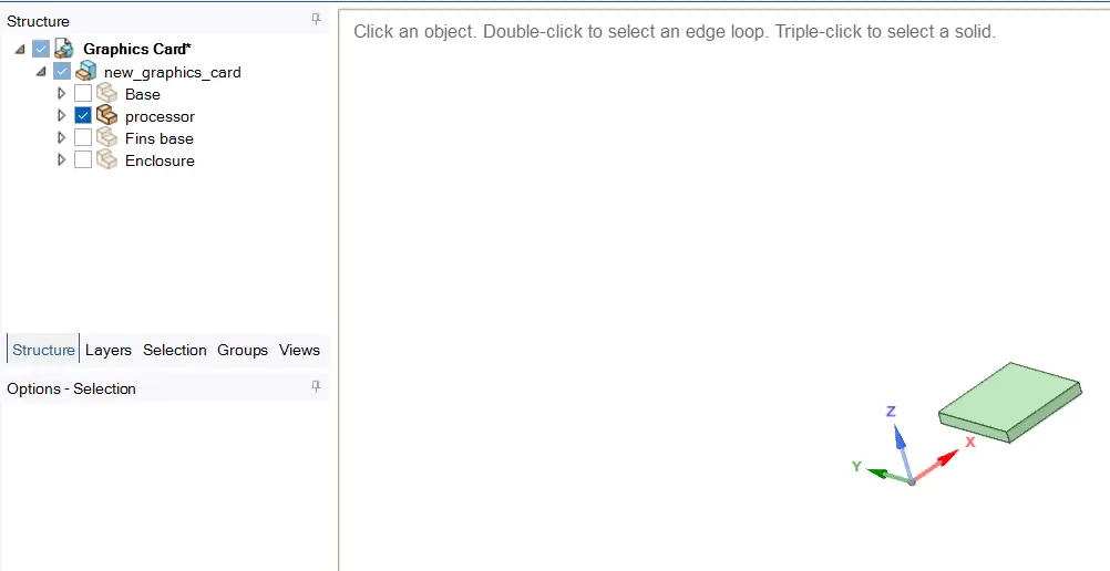
2. Processor - where the heat is generated
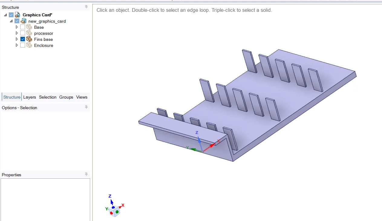
3. Fin Base - Heat generated in processor is conducted through the fin.
Assembly of the parts of Graphic Card
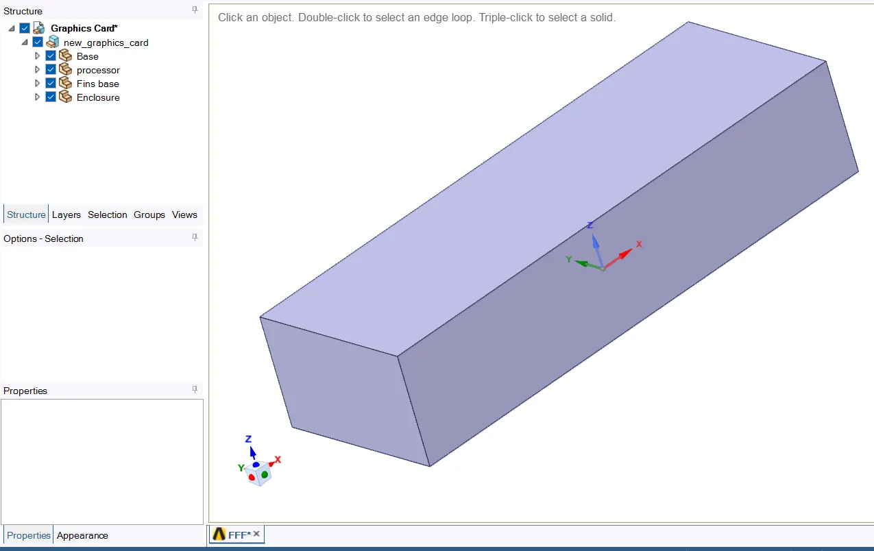
This geometry is enclosed in a box
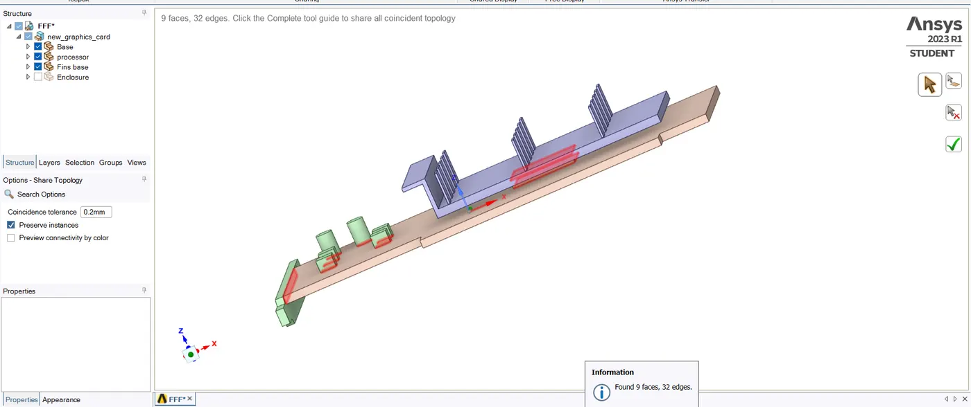
Topology is set to Share

To get the conformal mesh we must enable sharing
Workbench - Share
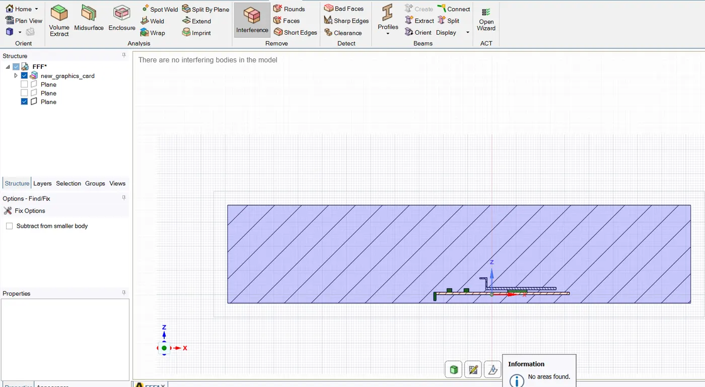
Make sure that there is no interference present in the geometry
Materials used in Graphics Card
- Fin Base - Aluminium
Thermal Conductivity of 180 W/m-K
2. Base - Steel
3. Processor - Silicon
4.Fluid - Air
Running the simulation for three different velocities from 1 m/sec to 5m/sec
- Velocity - 1 m/sec
- Velocity - 3 m/sec
- Velocity - 5 m/sec
Make sure that mesh formed is Conformal
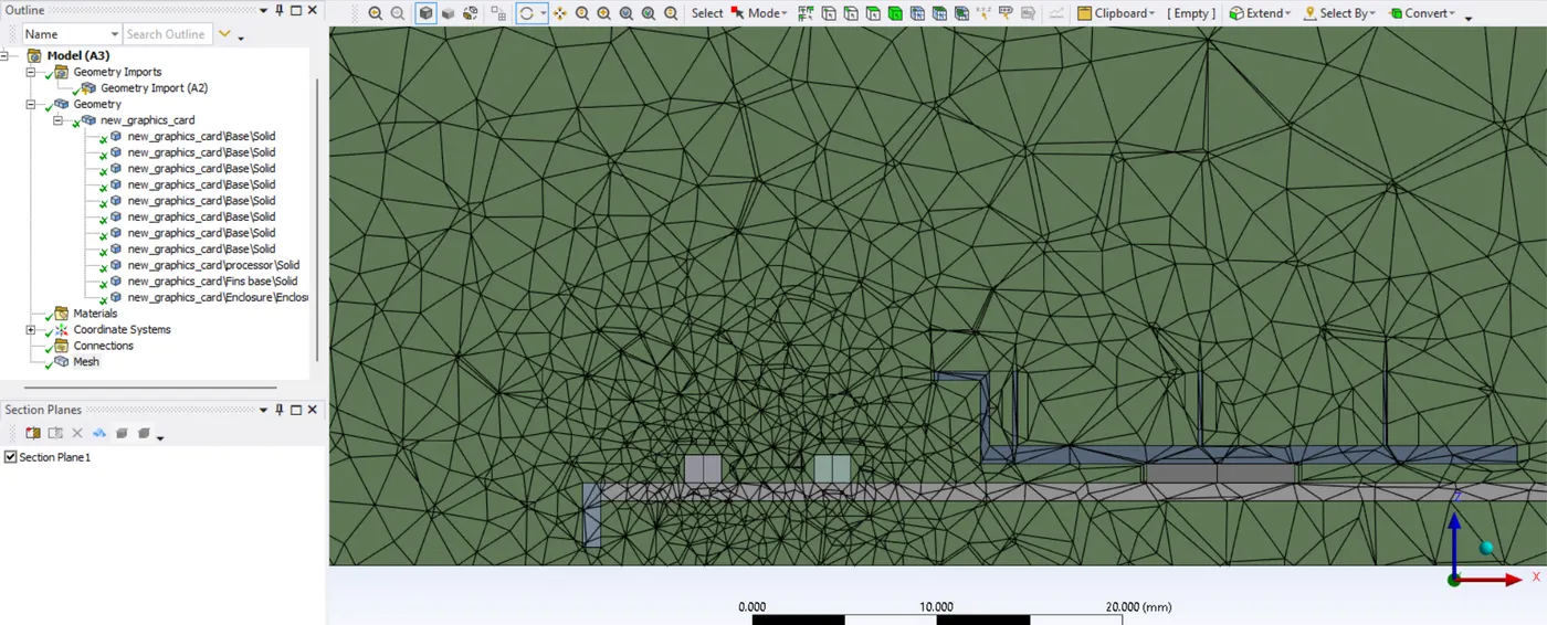
Mesh Refining
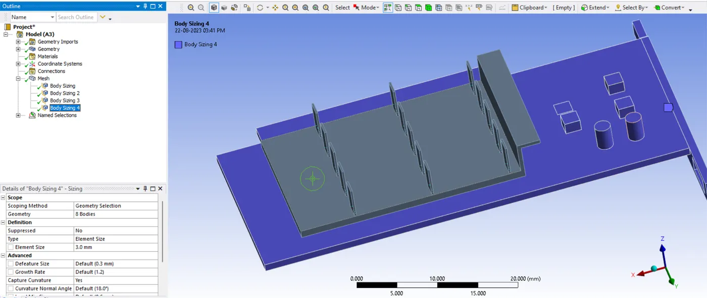
Different meshing size for each part is selected
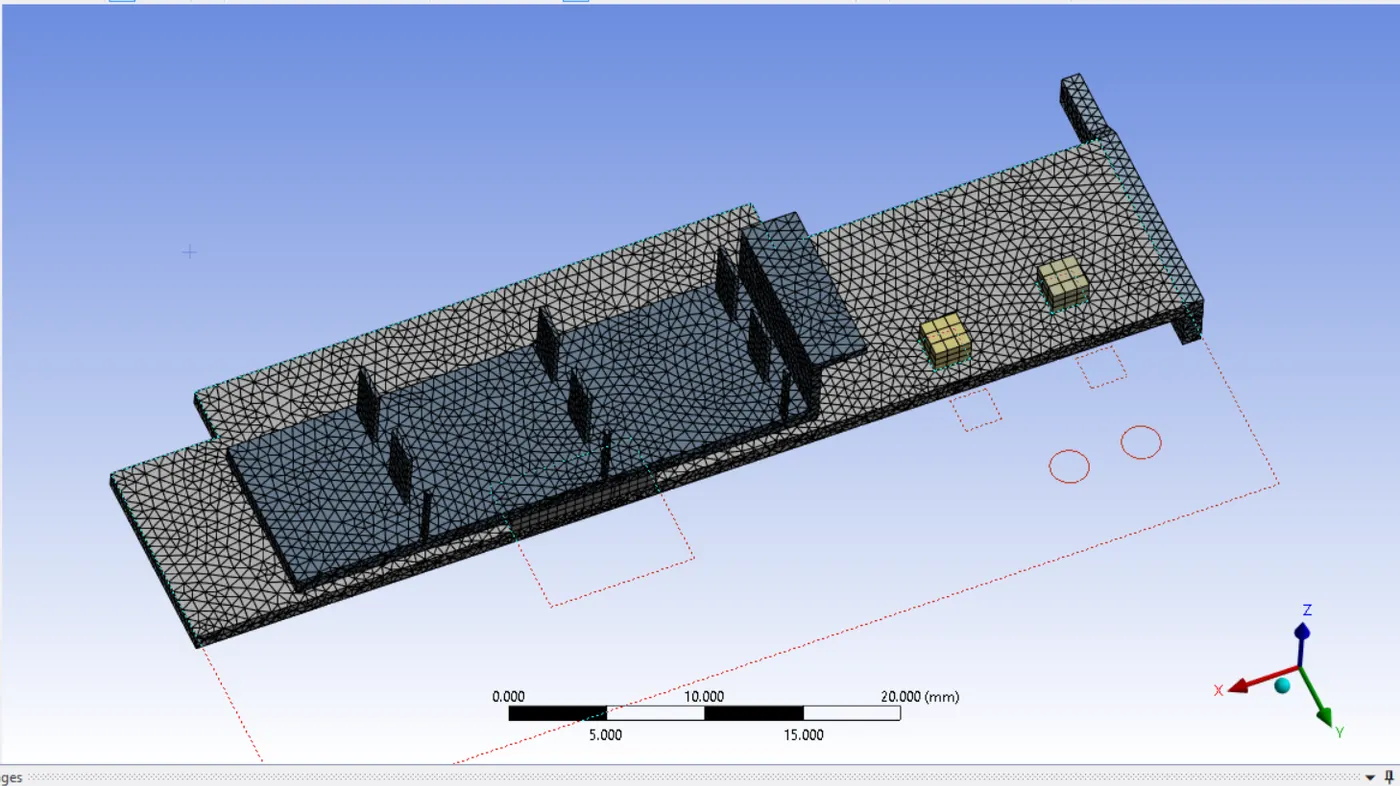
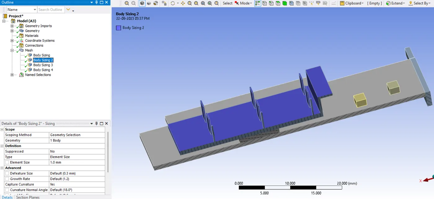
FIN BASE
Element Size -1 mm for fin base ( Element Size is selected as per dimensions of graphics card )
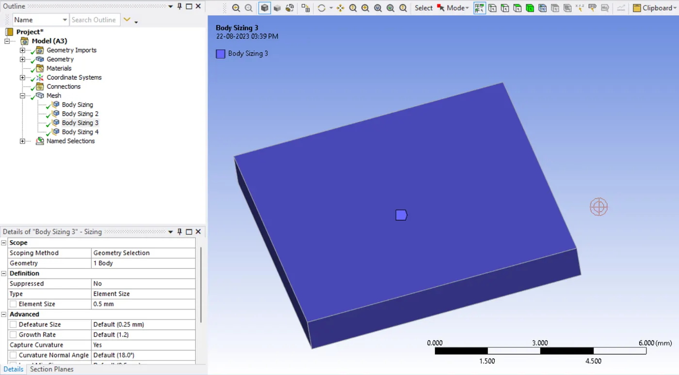
PROCESSOR
Element Size -0.5 mm for fin base ( Element Size is selected as per dimensions of graphics card )
SOLID BODY
Element Size -3 mm
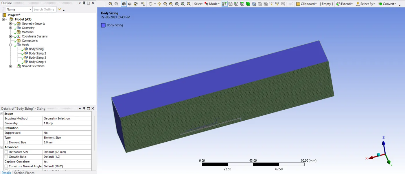
MESH for Enclosure
Element Size and Maximum Size is set to 5 mm.
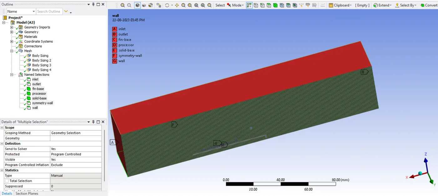
NAMED SELECTION
Fluent Setup ( Physics)
Steady State , Pressure Based Model ( as velocity varies from 1 m/sec to 5 m/sec, for less values of Mach Number The Pressure Based Model is well suited.)
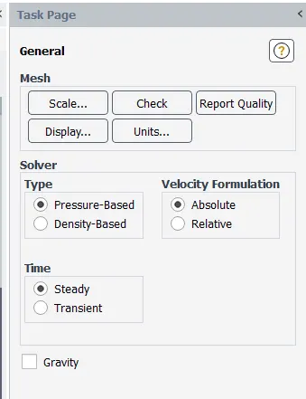
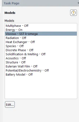
Energy Equation is turned on as the temperature ( thermal analysis) is invovled and SST K -Omega Turbulence Model is used.
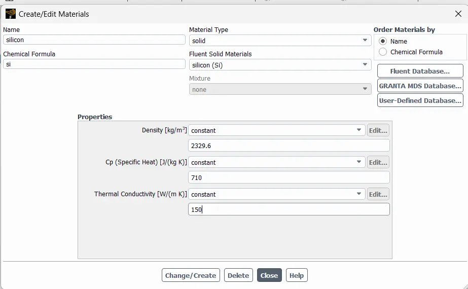
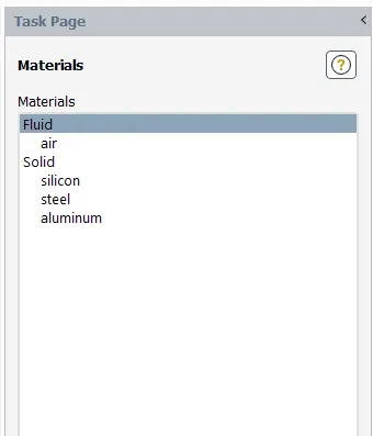
Two materials are loaded from Fluent Database - Aluminimum and Steel
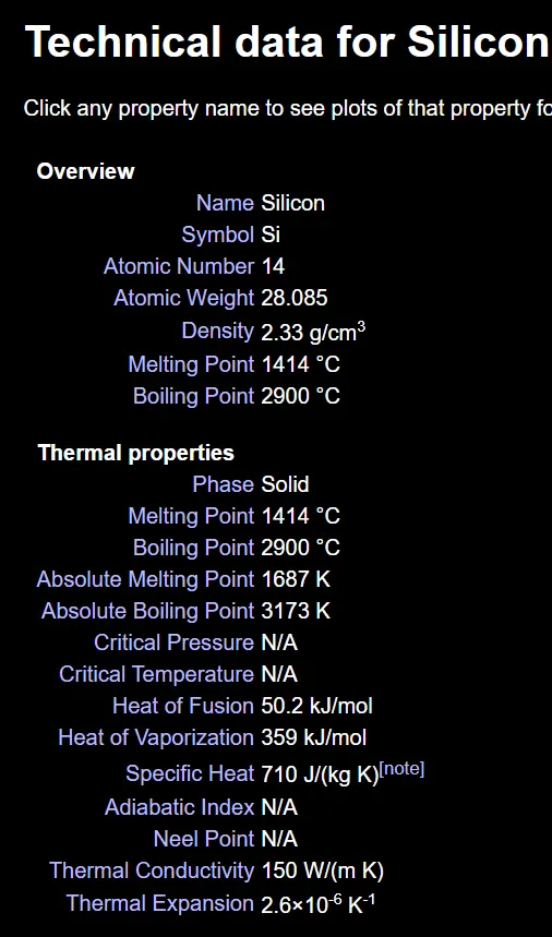
another one ( Silicon) is defined as it was not present in the list of solid materials)
The data source - periodictable.com
Cell Zone Conditions
Fin base , Processor and Solid body are defined as Solid and Enclosure is set as fluid ( which carries Air)
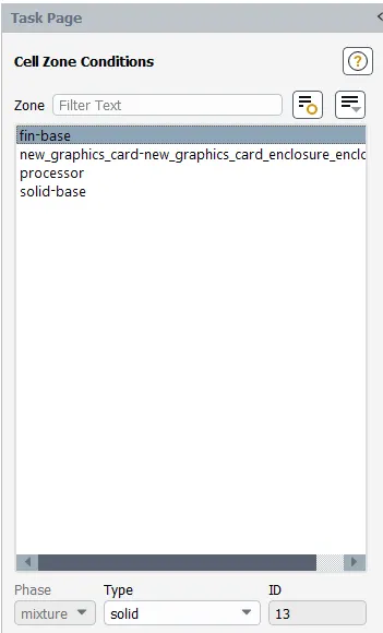
The material for Processor is Silicon and The Heat is generated in Graphics Card due to Processor. Hence it is termed as an energy source.
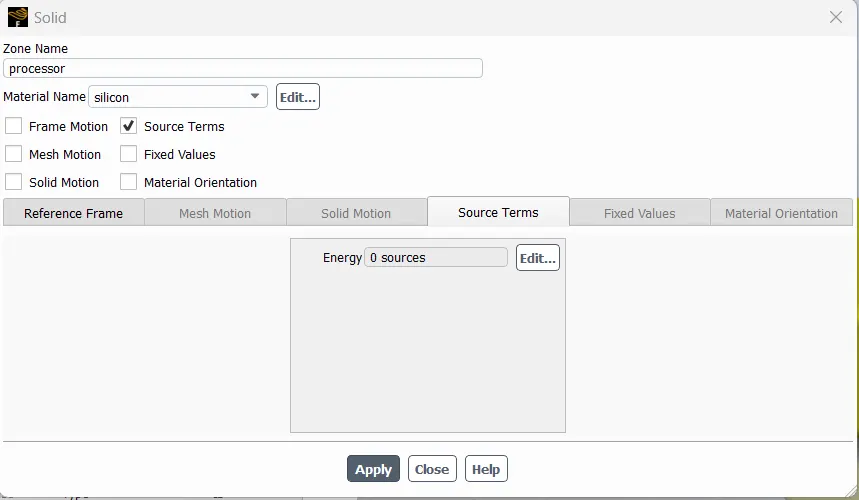
The processor needs 80 to 140 watts of power and a top model of graphics card needs between 110 and 270 watts
Considering Power Source to be of 5 Watts
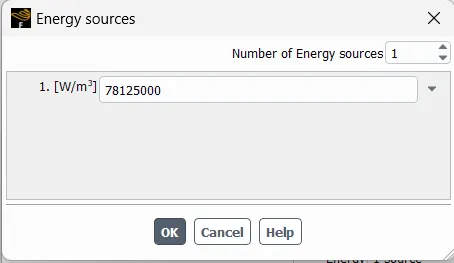
To calculate Energy Source in W/ m^3
we know the volume of Processor - 8mm* 8 mm *1 mm = 64 mm^3 = 0.000000064 m^3
Enegry Source = 5 / 0.000000064 = 7,81,25,000 W/ m^3
Boundary Conditions
Inlet - Velocity Inlet
Symmetry Wall - Symmetry
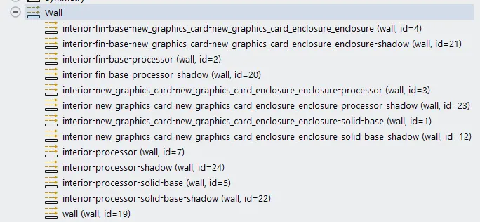
Wall - Thermal Conditions - Coupled
- Interior fin base processor
- Interiore new graphics card enclosure - processor
- Interior - Processor
- Interior Solid base - Processor
Rest of wall components having no slip condition
Outlet - Pressure Outlet
Report Definitions
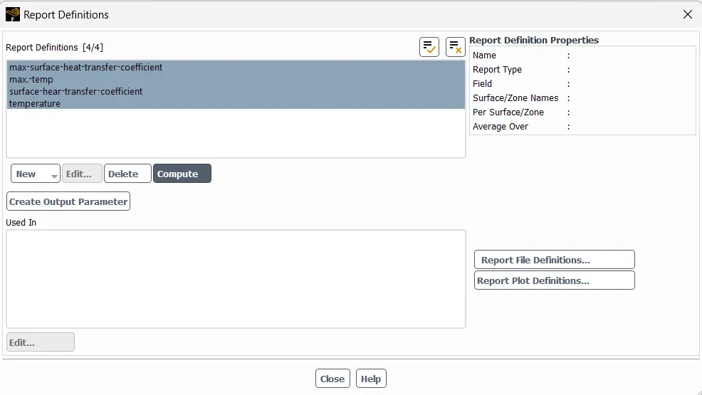
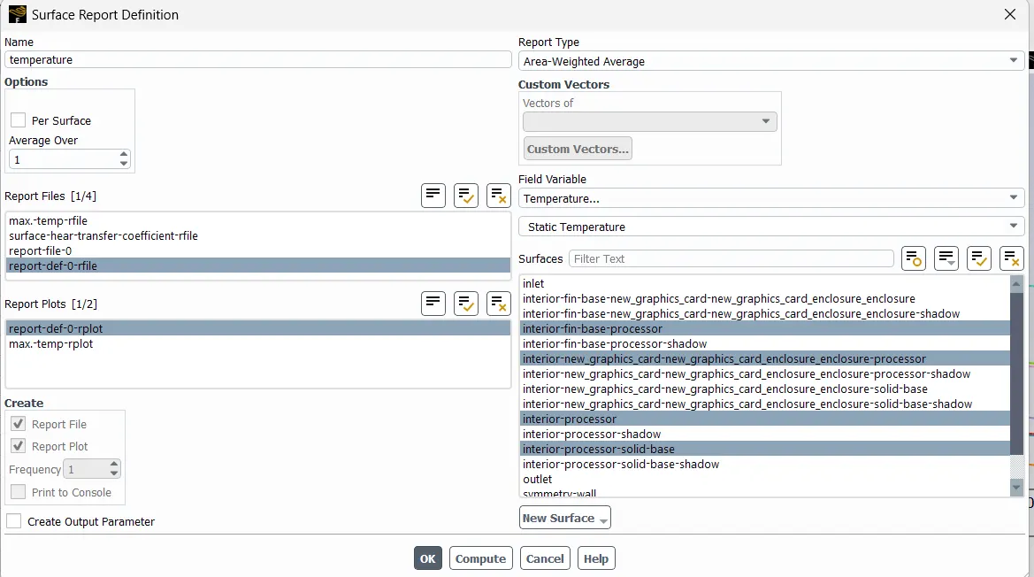
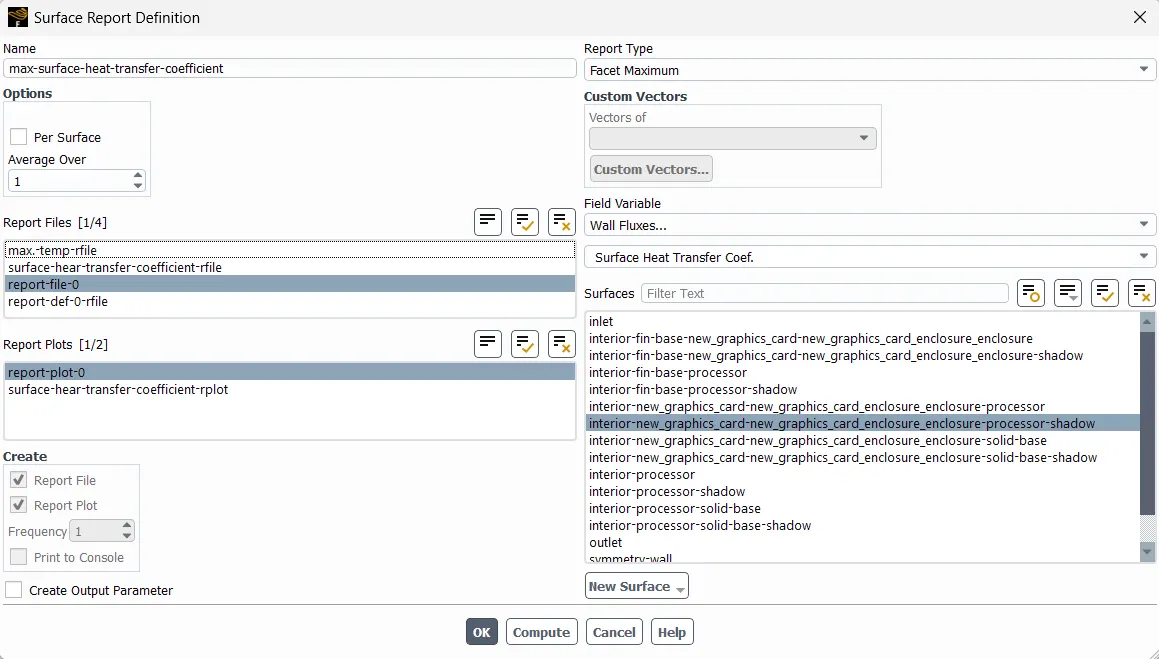
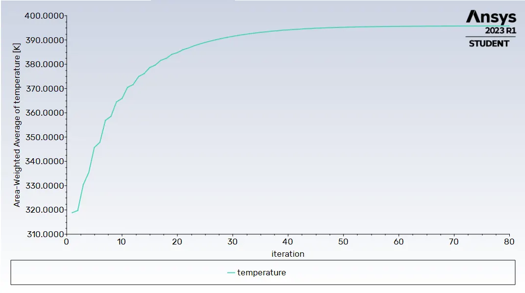
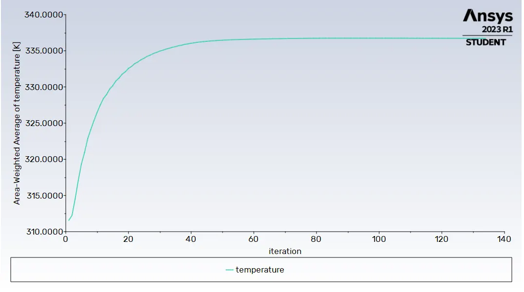
For Average Wighted Temperature attained by Processor
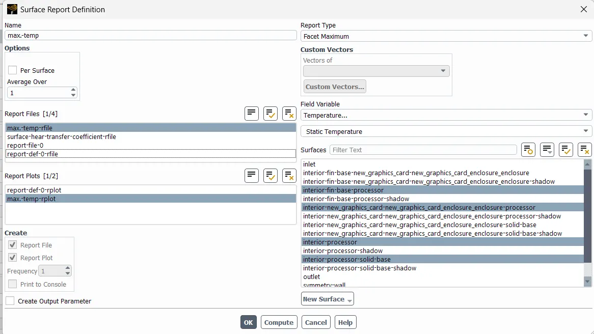
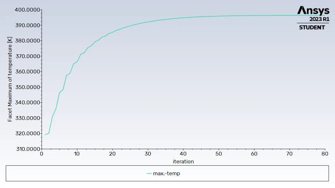
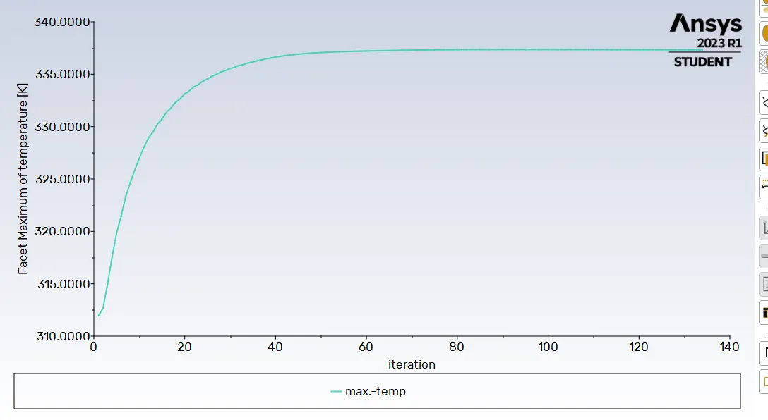
Facet Maximum is used to get the maximum temperature
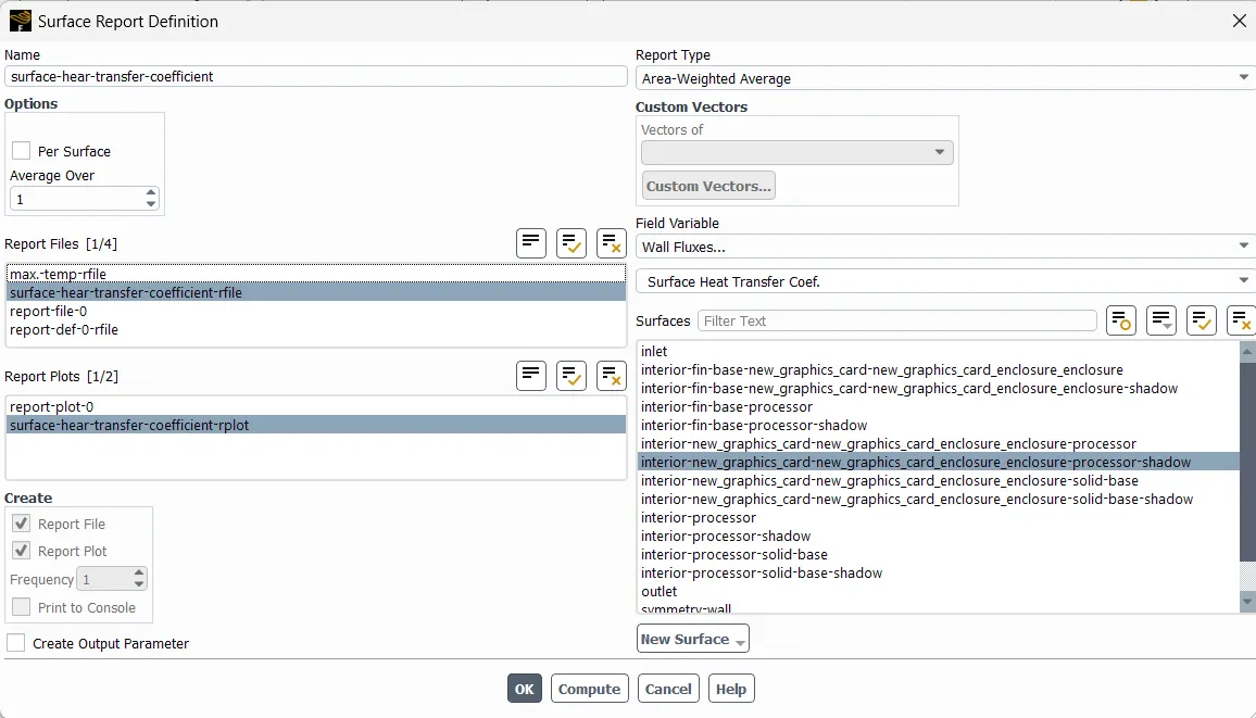
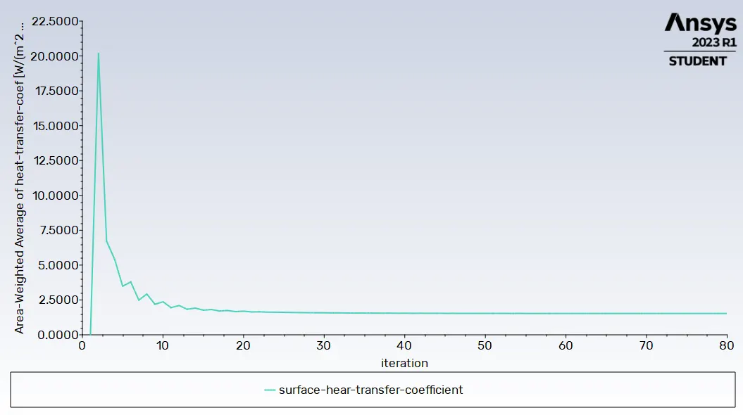
Surface Heat Transfer Coefficient
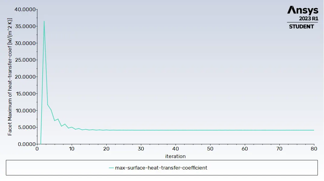
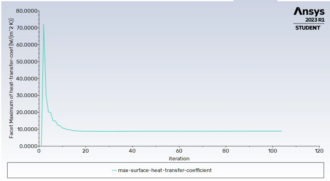
Max Surface Heat Transfer Coefficient
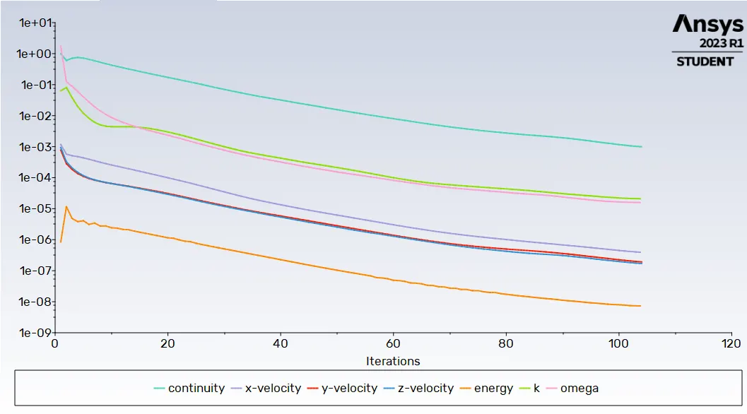
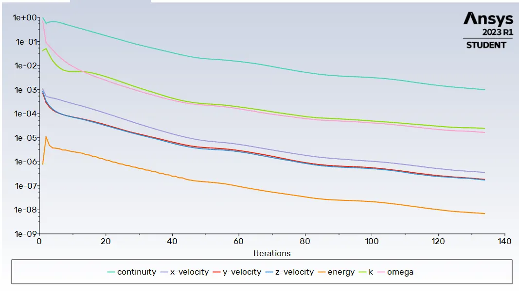
The convergence criteria is set to 0.001 , i.e when the differences in corresponding values of iterations falls below the value of 0.001 the solution is said to be converged.
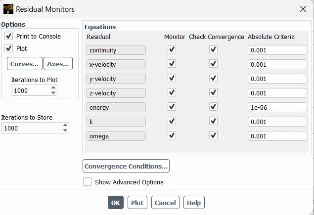
No of Iterations set to - 500
Intialization - Hybrid
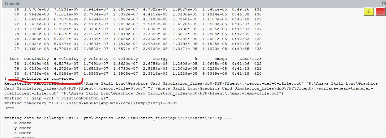
Solution is converged after 80 iterations
Scaled Residuals
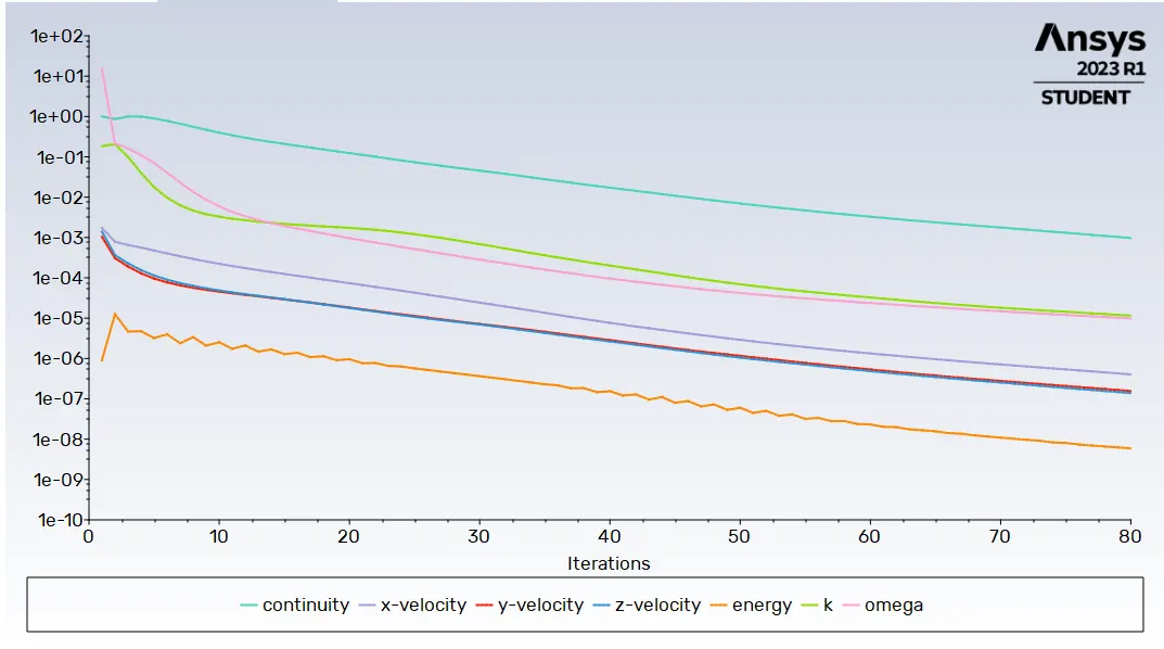
As we can see when all the graph values reaches till 1e-3 i.e 0.001 the solution is convegred.
Hence from the above information and images it is proved that the solution is coneverged.
maximum temperature and heat transfer coefficient attained by the processor.
Average Temperature - 395.77161 [K]
Maximum Temperature - 396.39377 [K]
Surface Heat Transfer Coefficient - 1.5283492 [W/(m^2 K)]
Maximum Surface Heat Transfer Coefficient - 4.1391697 [W/(m^2 K)]
Post- Processing
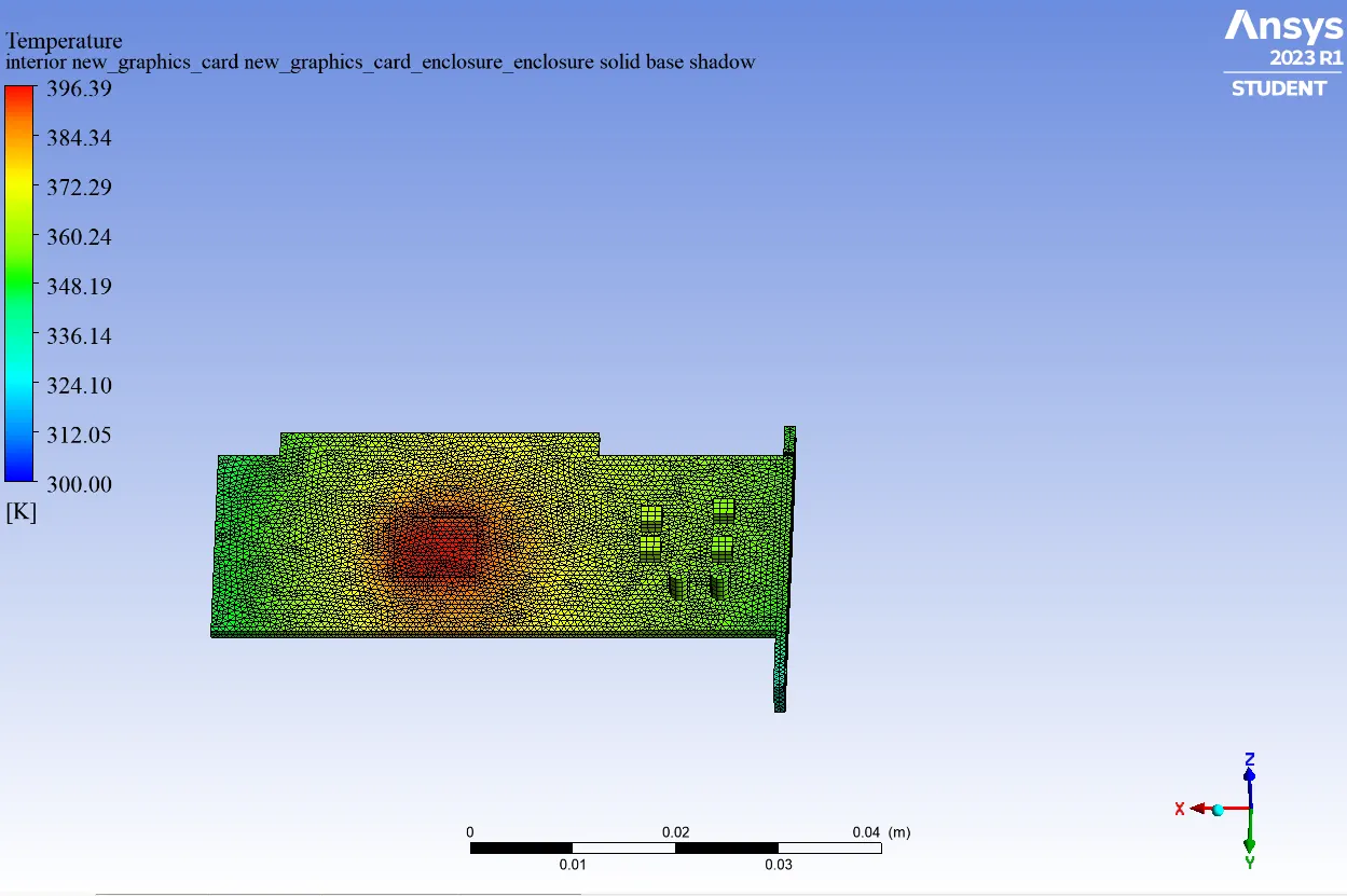
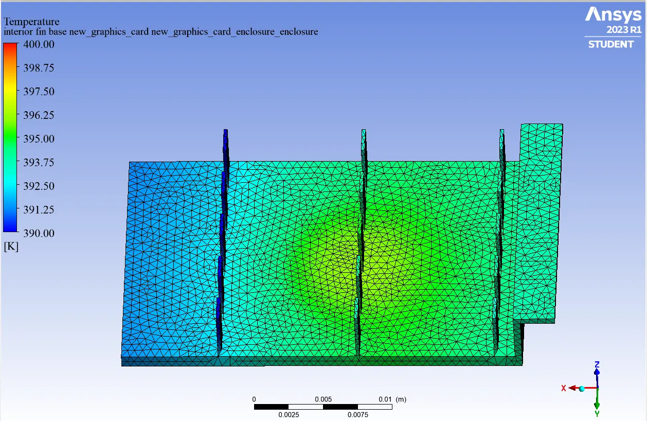
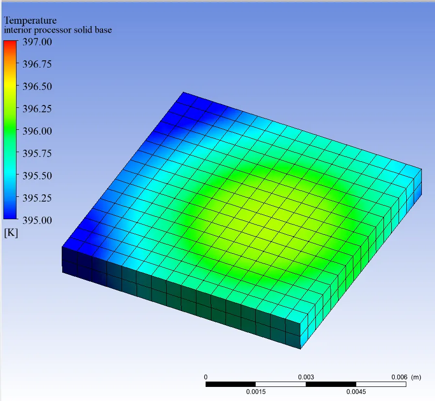
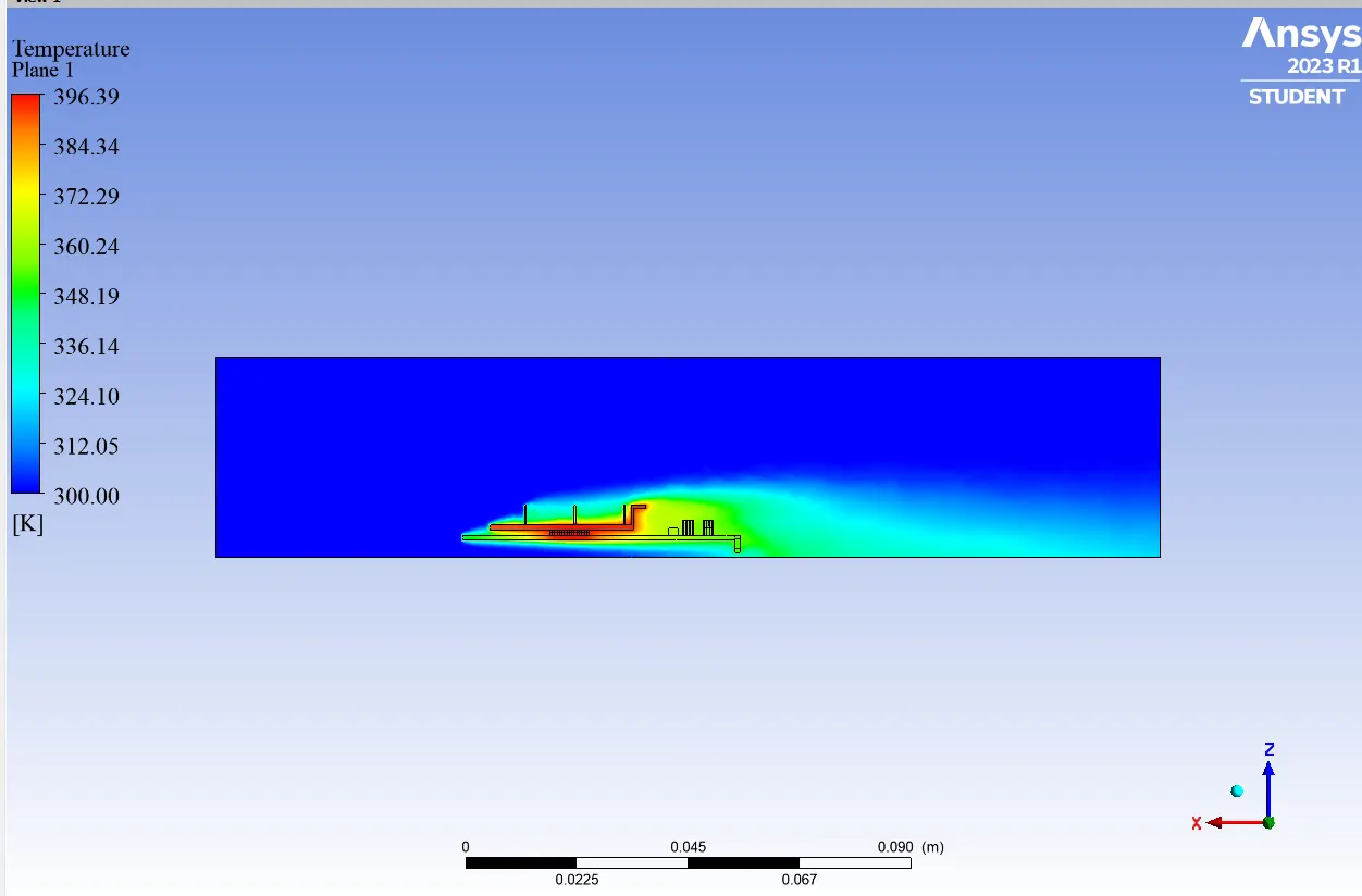
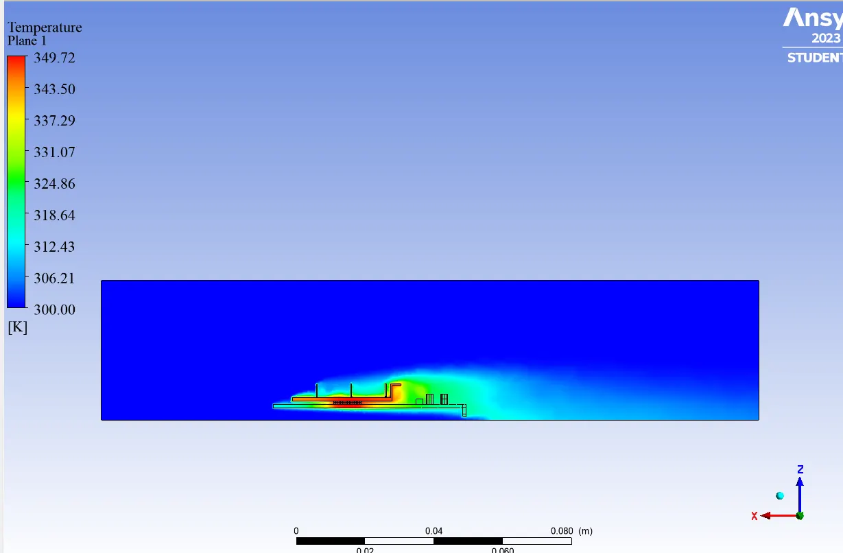
Temperature Contours
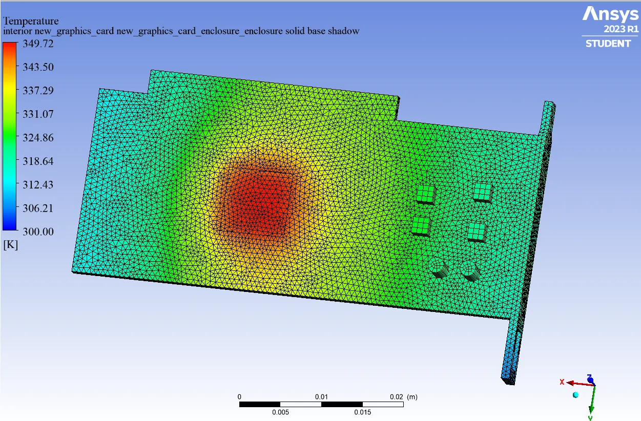
Solid Base
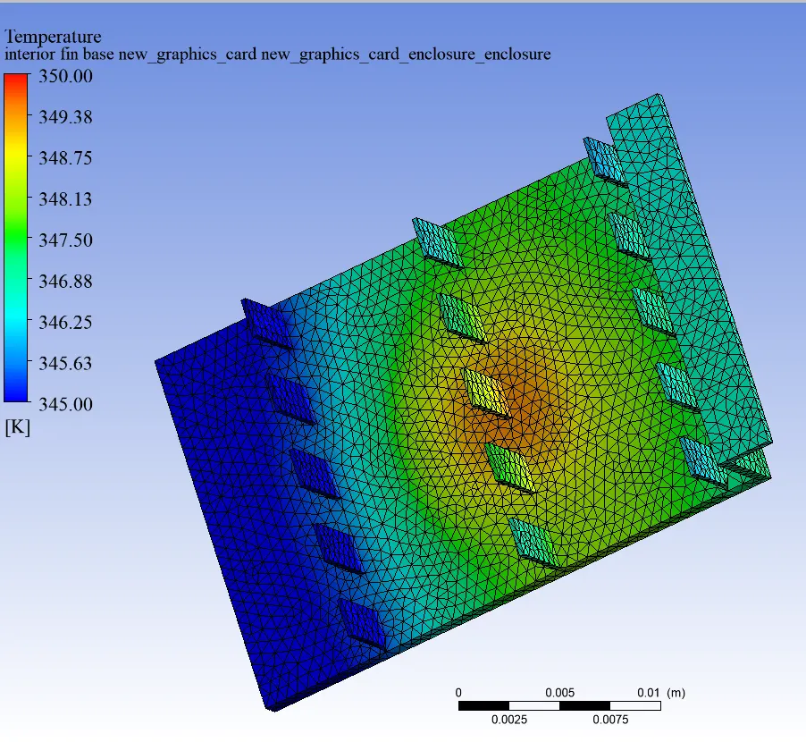
Fin Base
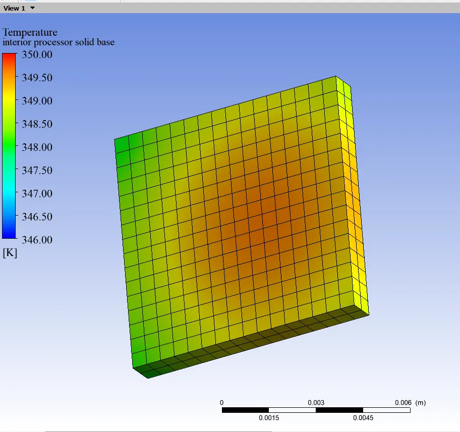
Processor
Temperature Range is varied
CASE 2
Velocity - 3 m/ sec
Scaled Residuals
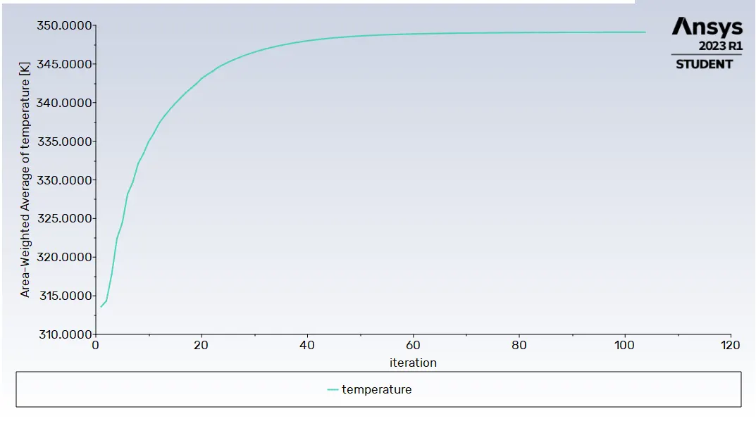
Average Temperature - 349.11627 K
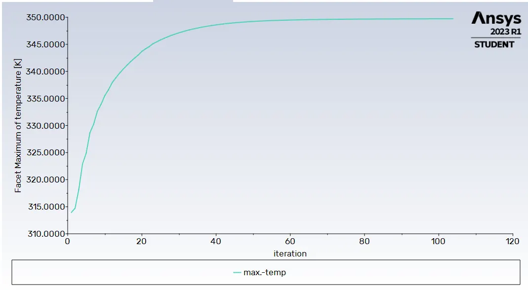
Maximum Temperature - 349.72516 K
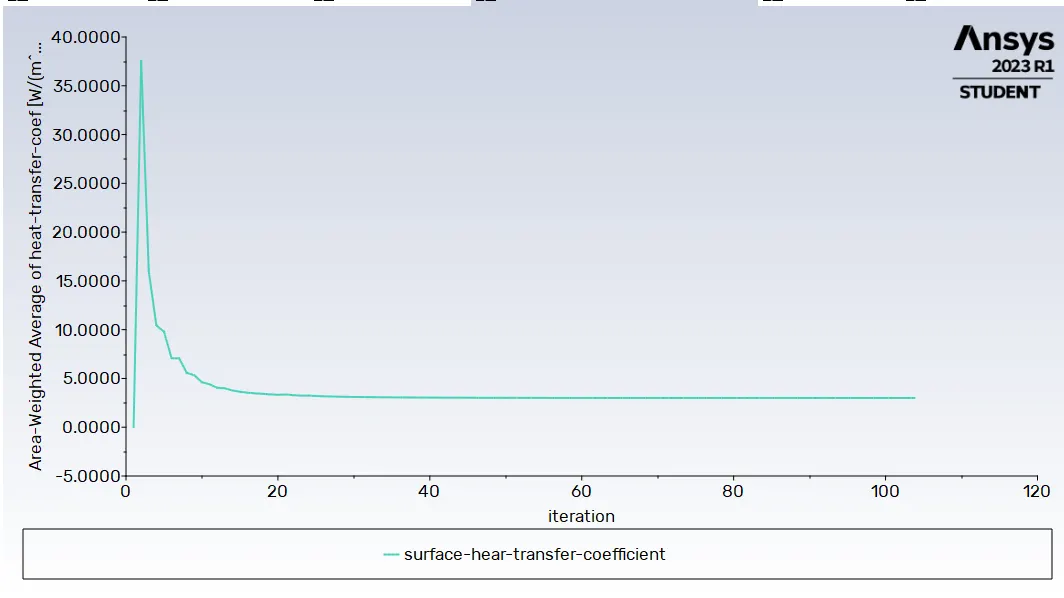
Surface Heat Transfer Coefficient - 2.9959748 [W/(m^2 K)]
Maximum Surface Heat Transfer Coefficient - 8.8644695 [W/(m^2 K)]
POST- PROCESSING
CASE-3
Scaled Residuals
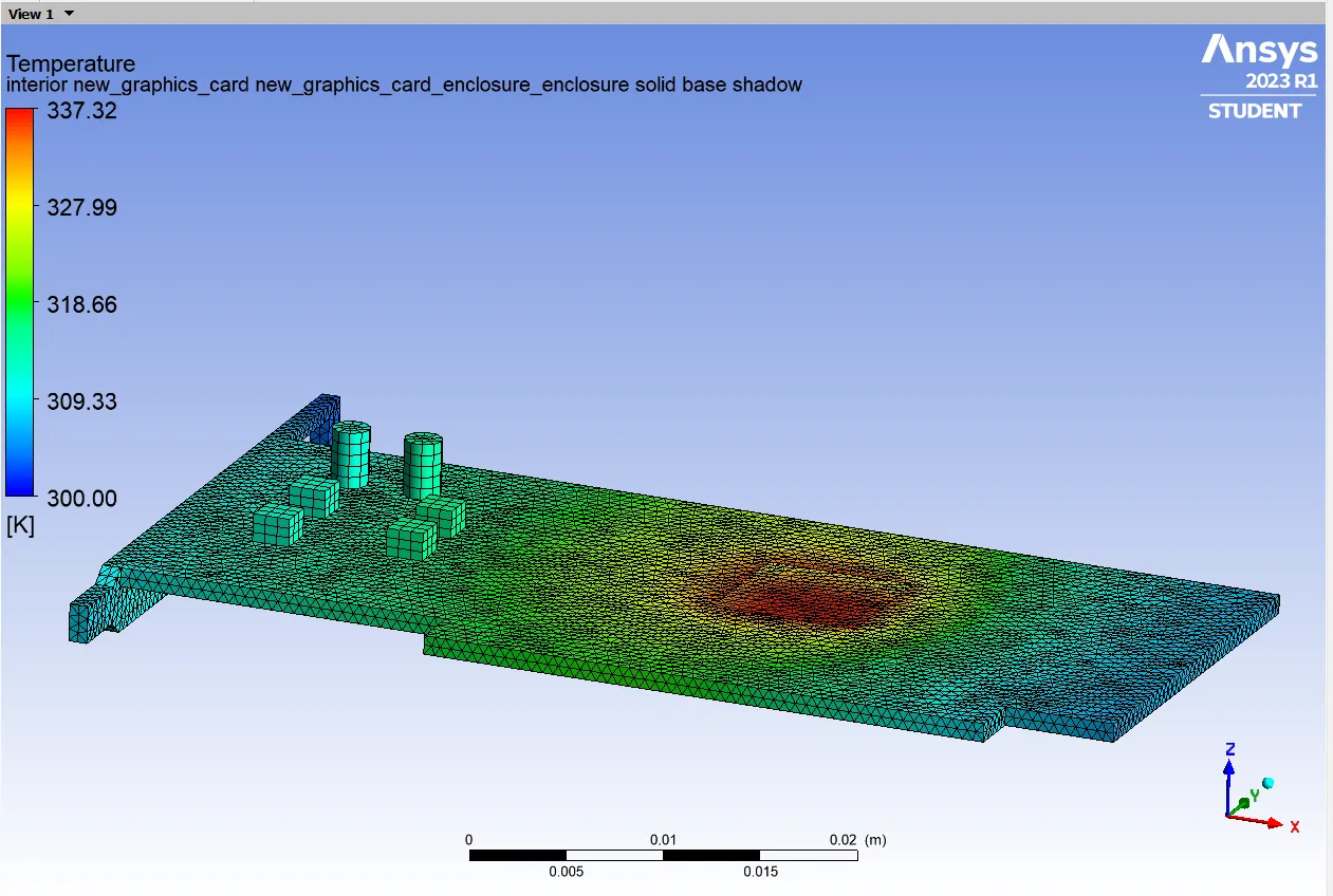
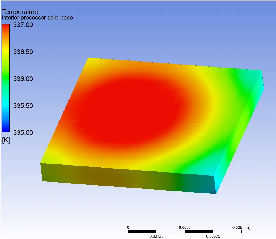
Average Temperature - 336.72093 [K]
Maximum Temperature - 337.32932 [K]
Surface Heat Transfer Coefficient - 5.9527384 [W/(m^2 K)]
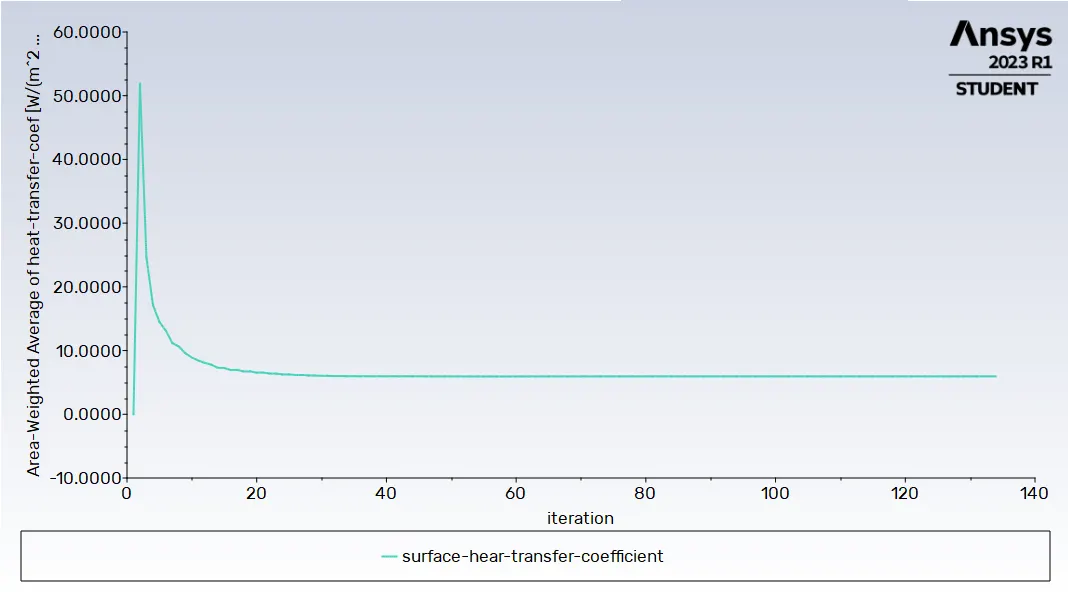
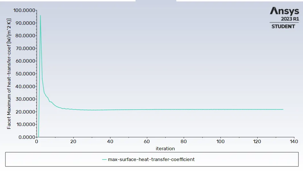
Maximum Surface Heat Transfer Coefficient - 21.8284 [W/(m^2 K)]
POST - PROCESSING
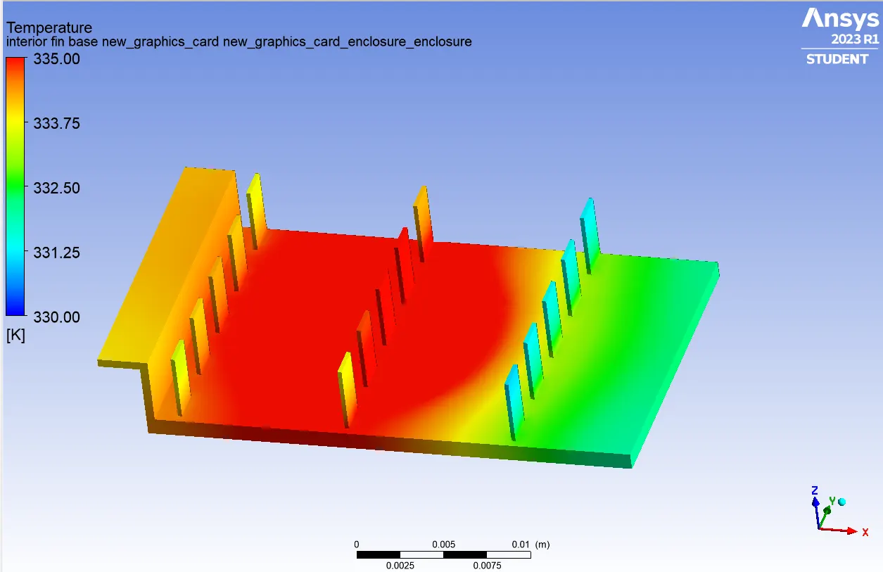
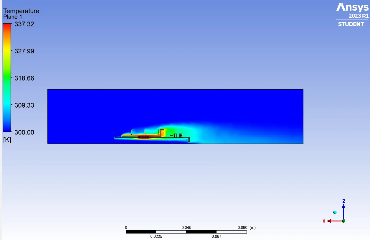
Maximum Temperature and Heat Transfer Coefficient attained by processor in all the cases.
| Sr. No | Velocity | Average Temperature (K) | Max . Temperature (K) | Surface Heat Transfer Coefficient W/(m^2 K) | Max. Heat Transfer Coefficient W/(m^2 K) |
| 1 | 1 m/ sec | 395.77161 | 396.39377 | 1.5283492 | 4.1391697 |
| 2 | 3 m/ sec | 349.11627 | 349.72516 | 2.9959748 | 8.8644695 |
| 3 | 5 m/ sec | 336.72093 | 337.32932 | 5.9527384 | 21.8284 |
CONCLUSION
1. As the velocity increases effective heat transfer rate and surface heat transfer coefficient also increases which lowers the maximum temperature attained by the processor.
2. As can be seen the the temperature contour images, the potential hotspots occur where the processor is coming in contact with other bodies like fin base and solid base ( as the source of energy generation is the processor)
we can consider areas showing red dots as potential hotspots as they are carrying the highest temperature.