Week 2 Challenge : Surface meshing on a Pressure valve
Detailed Report on Week 2 Content
Week 2 Lecture 1
Model - Pressure Valve
Content - Geometry cleanup in topo mode
Tool
Checks - Geomerty Checks
Tick on paramters which needs to be checked
Example - Single cons , Double cons , Triple cons , Cracks , Collapsd cons etc
After clicking on ' Execute' , some errors will be shown
In the Geometry , Single cons are shown with red lines.
First task is to clear single cons.( Preview can be seen on geometry by selecting single con errors with white lines)
Solving the errors is called ' Topo Cleanup'
We can also use Visiblity Tool o check single cons
Turn On only ' Single Con' Icon
Use Ctr+ Shift for wireframe mode
We need to patch the surfaces in order to provide a closed model for meshing.
Faces - New - Surface Type
Options for Surface Type
Existing Surafce - Filling hol in existing surface
Planar -
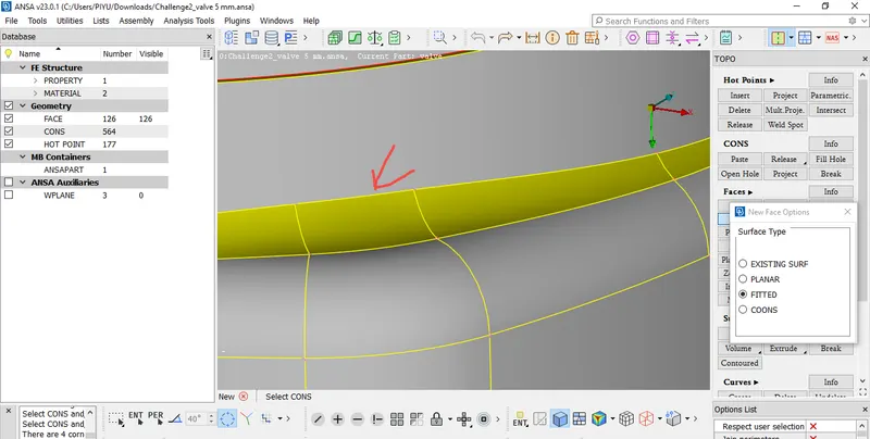
Fitted - Same as coons , we can check the alternate option for surface.
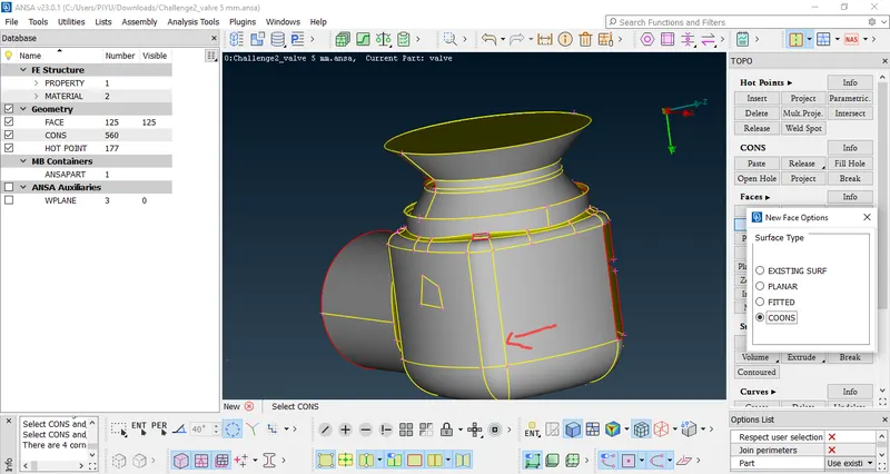
Coons - Select single con , with the help of tool 'Loop' , all the other single cons which are connected to the selected single con will automatically be selected.
Tool Name - Cons - Fill Hole - select hole- middle click
Imp Note -
1.When we select two single cons to form a surface , we need to make sure that their length is equal.
2.For circular surfaces , when we need veertical surface, loop mode is not recommened , entity mode is preferred.
3. For volumetric meshing we need our surface to be entirely closed.
4. For triplecons , check whether we can delete any of the surfaces if it is not required.
5. 'All' and 'Neighbour All' options are same.
6. 'And' and ' Neighbour First' opions are same.
7. ' And' and ' Not' options are opposites.
Use of Inot tool to understand how triple cons are formed.
Week 2 Lecture 2
We can check the geometry by ticking on all the parameters given.
We can alos check the Single Cons, Double Cons, Triple Cons with the help of visibility tools.
Also, we do not want smaller surfaces present in geometry because they can interfere while meshing. i.e if the mesh length is greater than length of those small surfaces , meshing cannot be performed.
So, we need to cut the lines which are very close to each other and are insignificant.
Tool
Faces -Cut
See the surfaces in PID Mode.
Week 2 Lecture 3
To Create a new PID Click On
PID Manager - Right Click - New - PSHELL - PSHELL - New Popup box - Assing the name ( Outlet , Inlet , Body
To Assign PID to parts of Geometry
Right Click on the name of PID - Apply - Selection of Surface - Middle Click
Hide the assigned PIDs by Turning of the bulb icon.
For Selection , we have lots of options
Entity - To select a single surface
PID - Selects the entire geometry ( Inside as weel as outside)
PID Region - Selects the outermost region
Meshing Process
1. Topological Cleanup
Geometry Check
Tools- Check - Geometry - Select parameters ( Single Cons)
Errors will be displayed
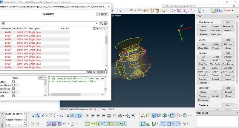
Geometry Correction
Creating Surfaces where single cons are present
Tools
Faces- New - Existing Surface - Select Con - Select Face - Middle Click
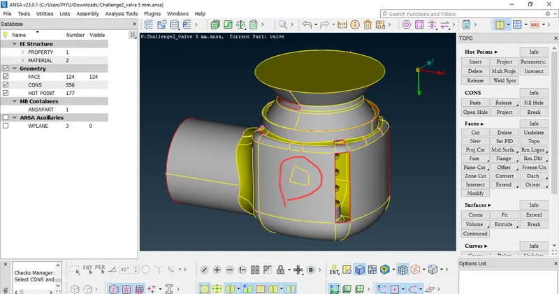
Faces- New - Coons - Loop - Select Con - Preview - Middle Click
Faces- New - Fitter - Loop - Select Con - Preview ( Alternate) - Middle Click
Cons - Fill Hole
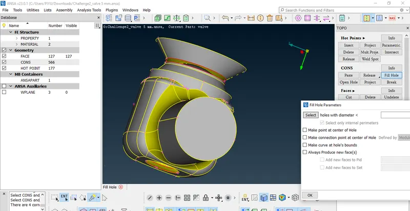
All the Errors are corrected
No signle cons present
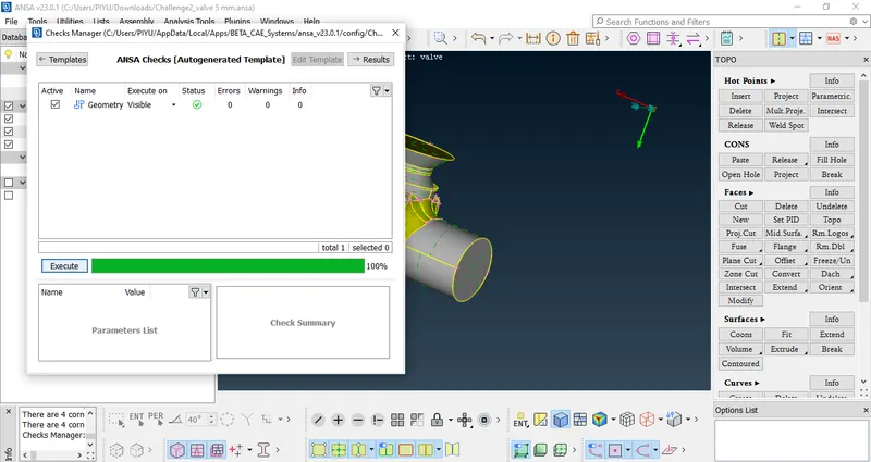
Forming an entirely closed surface for meshing
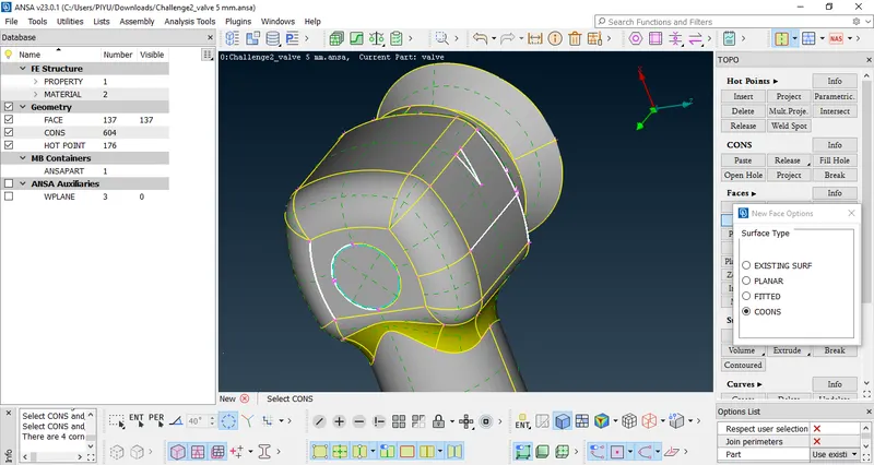
2. Deleting smaller lines
Faces - Cut
Before
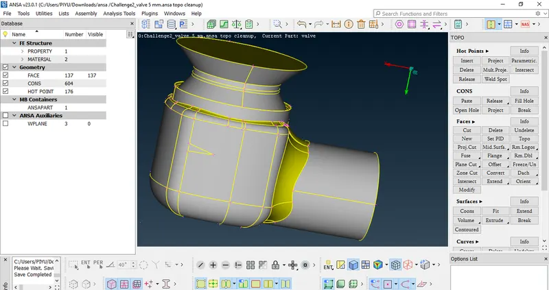
After
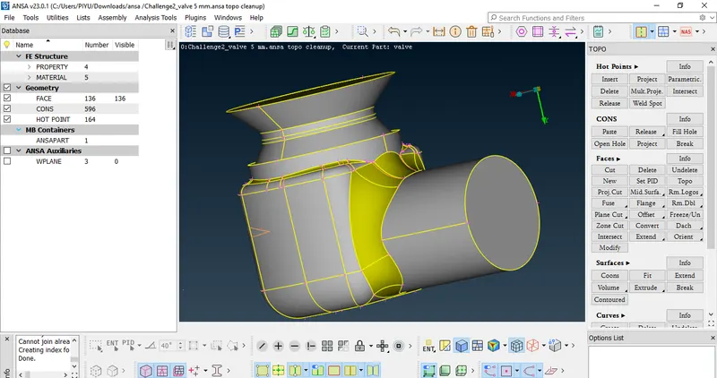
3. Forming New PIDs ( For Outer Surfaces)
Properties - New - PSHELL - PSHELL - Pop-up box - Name of PID
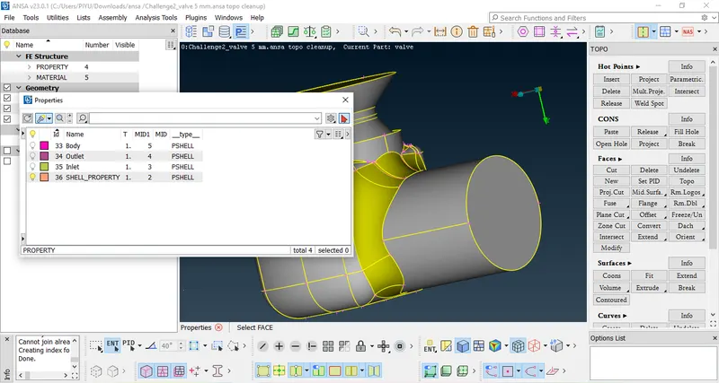
4. Assigning Names of PIDs to the Parts of Geometry
Right Click on Property Name - Apply - Select Part - Middle Click
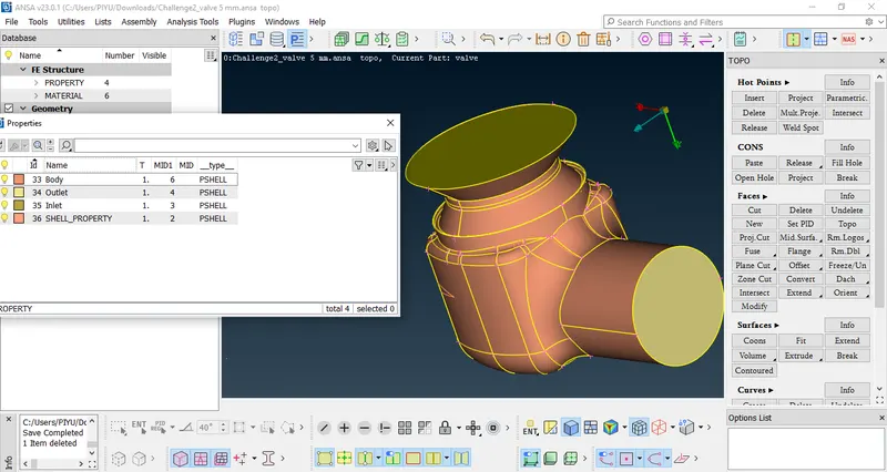
5. Assigning PIDs to Inner Surfaces
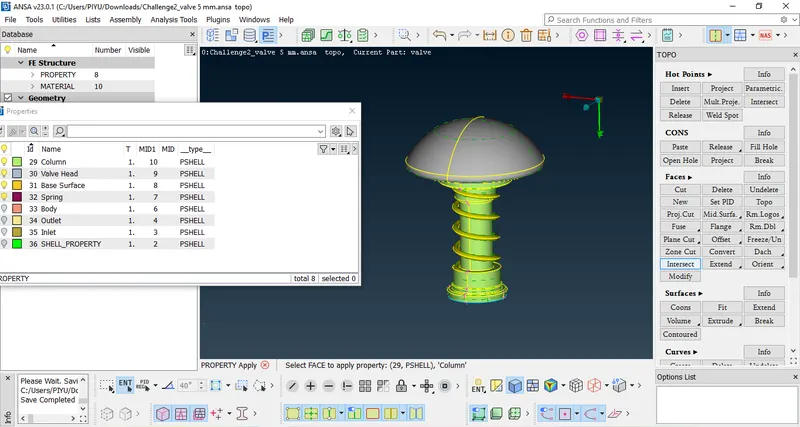
6. Use of Tool - Faces - Undelete to delete the dummy PIDs
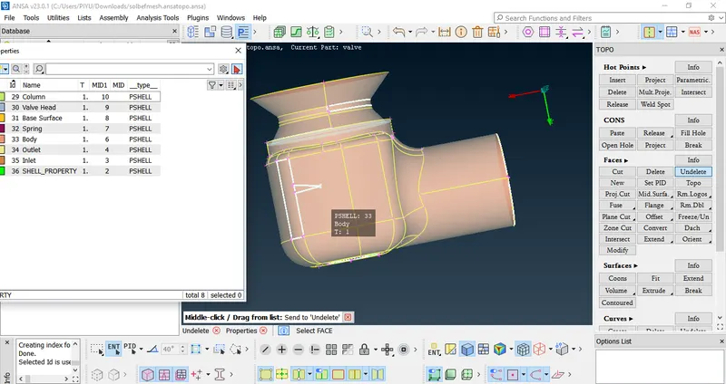
Retreiving deleted surfaces
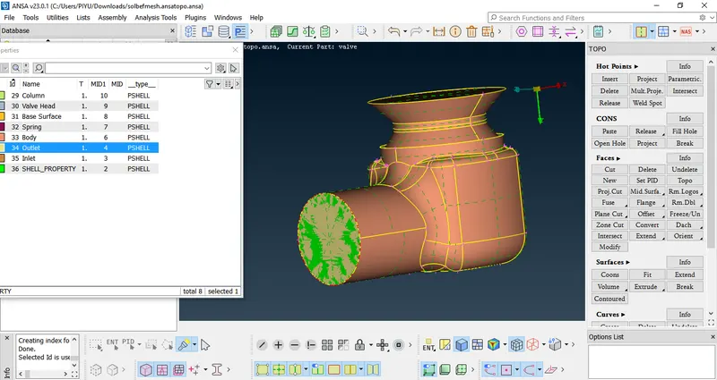
Deleting dummy PID
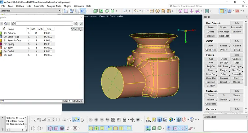
Week2 Lec 4 content is covered in this process
Used Spot Mesh
Mesh - Spot Mesh - PID Region - Selection - Middle Click
- Meshing Case 1
Target Length - 1 mm
Min Length - 0.5 mm
Max Length - 2 mm
Target length specified at four places
1. Perimeters - Length - Perimeter
2. Perimeters - Length - Macros
3. Mesh Parameters
4. Quality Criteria
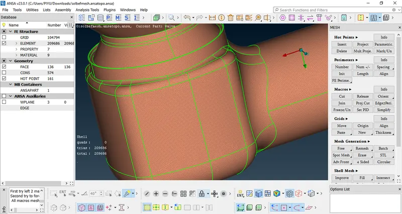
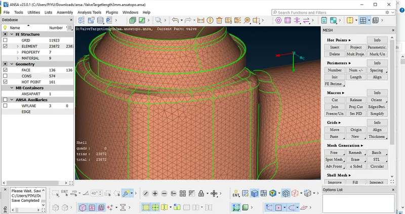
- Meshing Case 2
Target Length - 3 mm
Min Length - 1 mm
Max Length - 5 mm
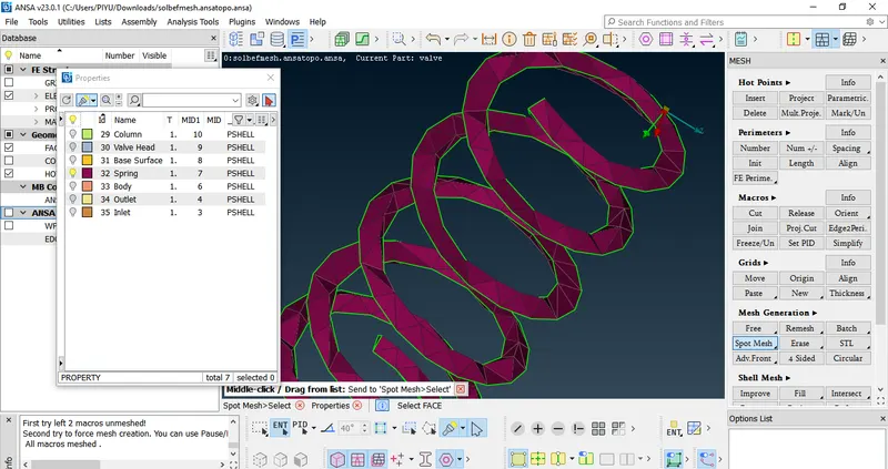
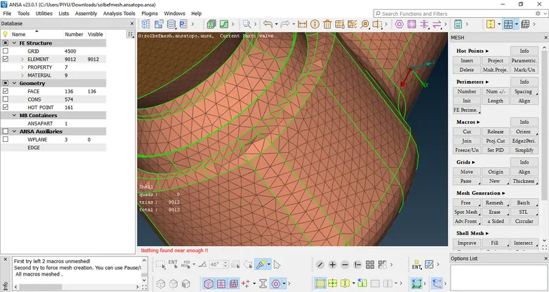
- Meshing Case 3
Target Length - 5 mm
Min Length - 3 mm
Max Length - 7 mm
Conclusion
Which case is giving better result ?
Out of three meshing the best result was given by first case i.e Target Length = 1 mm
As the target length reduces , finer the mesh quality becomes.
The no. of elements formed after descretization are highest in this case .
As the mesh/target length is smaller , It can include the surfaces having smaller perimeters.
But, if we increase the mesh length , the smaller surfaces can not be meshed / forcefully meshed , which does not give a fine meshing.
Like the Snap 1 of the case 3 shows , meshing is not proper for the spring element having perimeter=3 mm , when using 5mm Target Length.
The second best result were given by Case 2 i.e, 3 mm Target Length.
Elements are less than first case and more than the third case.