Week 6 - CHT Analysis on a Graphics card
Aim:
Perform a steady-state conjugate heat transfer analysis on a model of a graphics card. You can use appropriate materials of your choice for the simulation. Make sure to properly define the correct solid and fluid zones. Refer the video for further clarification and the model is provided below the video.
Run the simulation for best possible mesh with combination of coarse and refined mesh in different regions. Explain the reason for choosing the particular mesh settings.
Objectives:
- Run the simulation by varying the velocity from 1m/sec to 5m/sec for at least 3 velocities and discuss the results.
- Find out the maximum temperature and heat transfer coefficient attained by the processor.
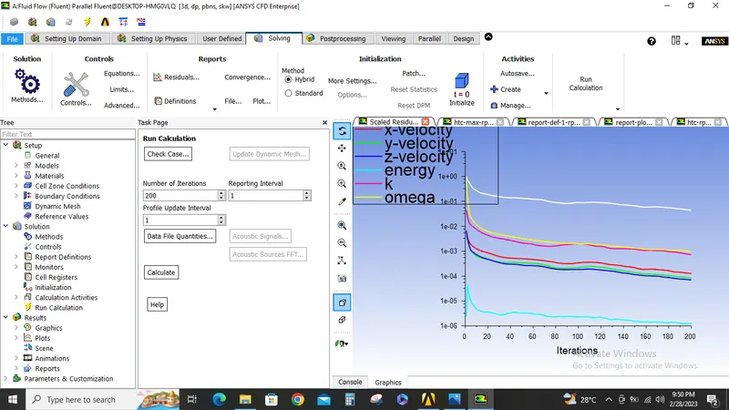
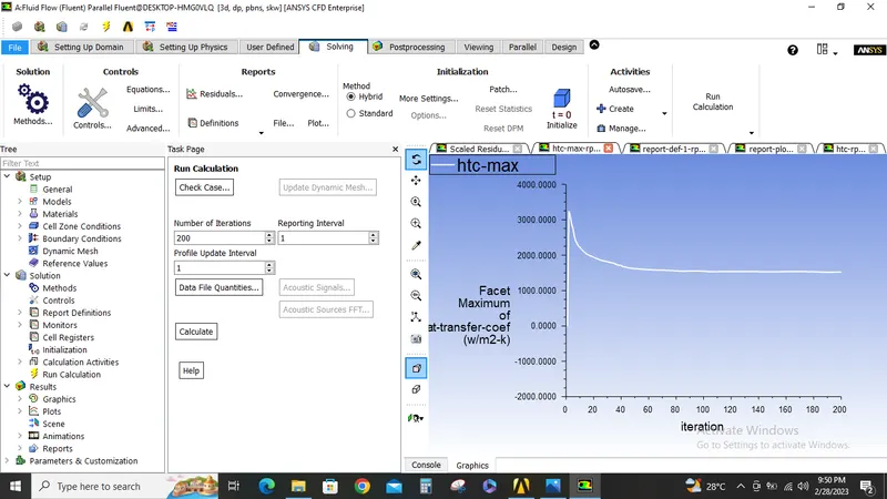
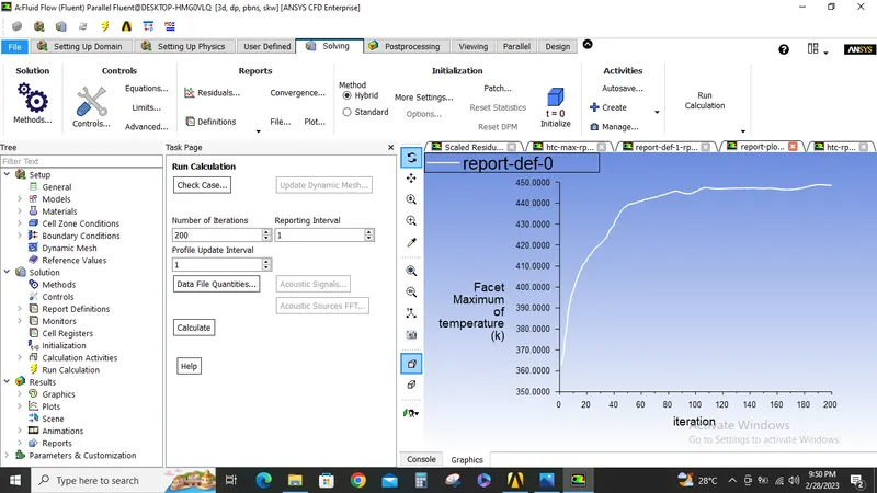
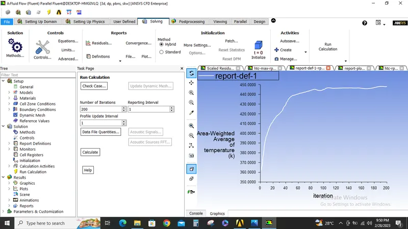
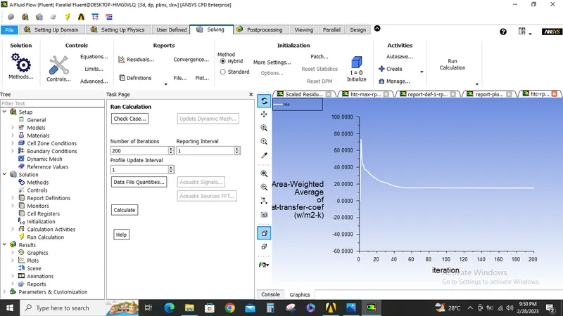
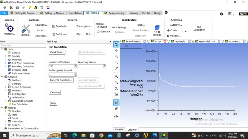
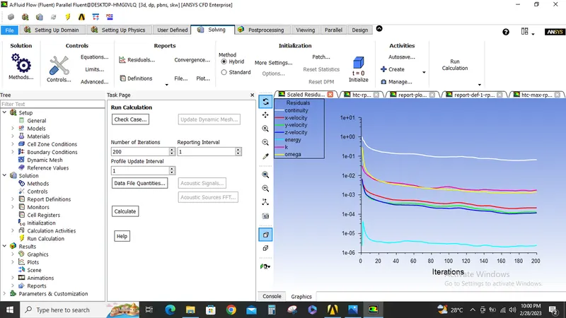
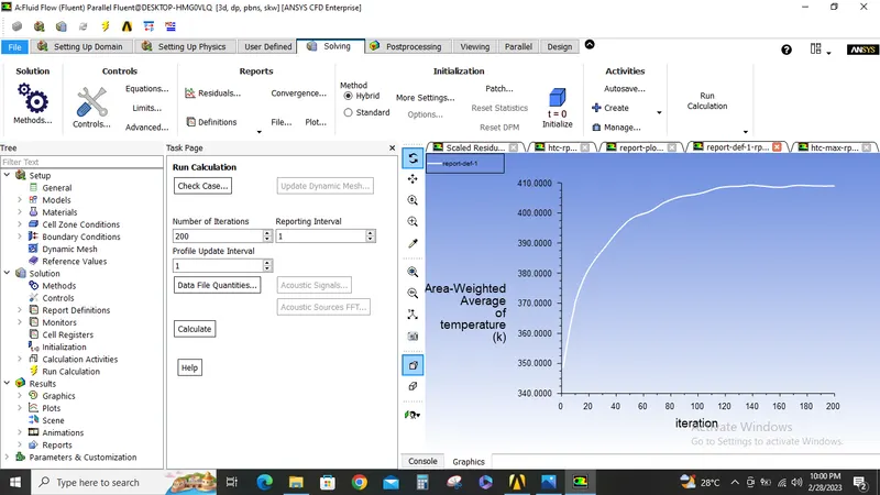
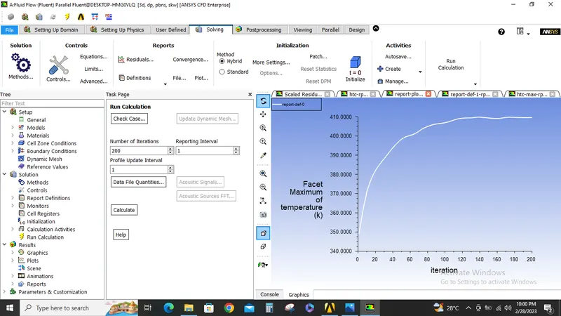
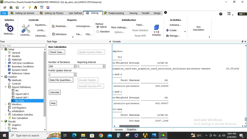
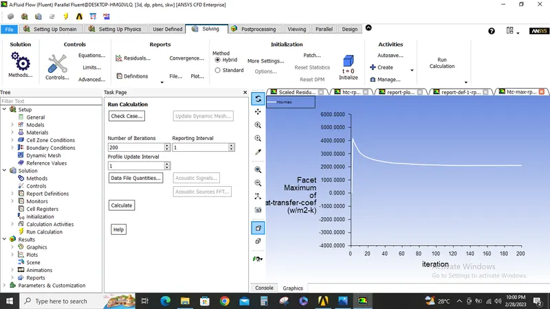
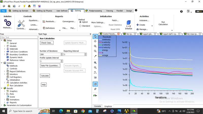
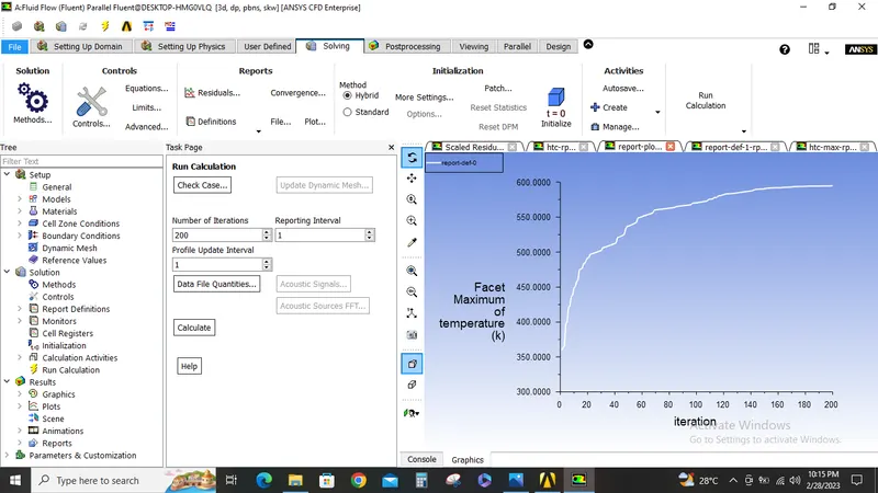
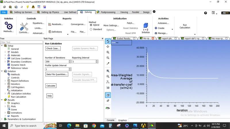
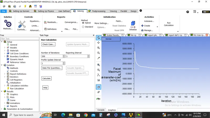
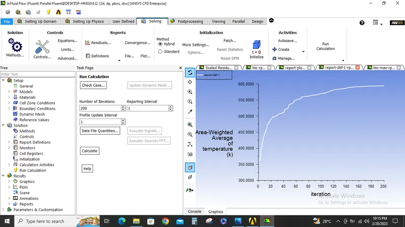
- Prove that the simulation has achieved convergence with appropriate images and plots.
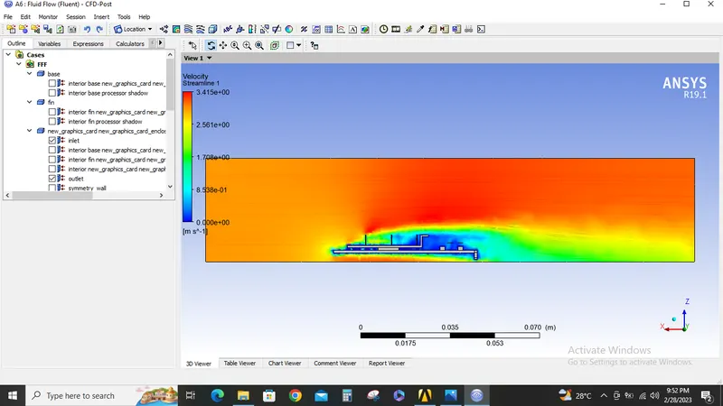
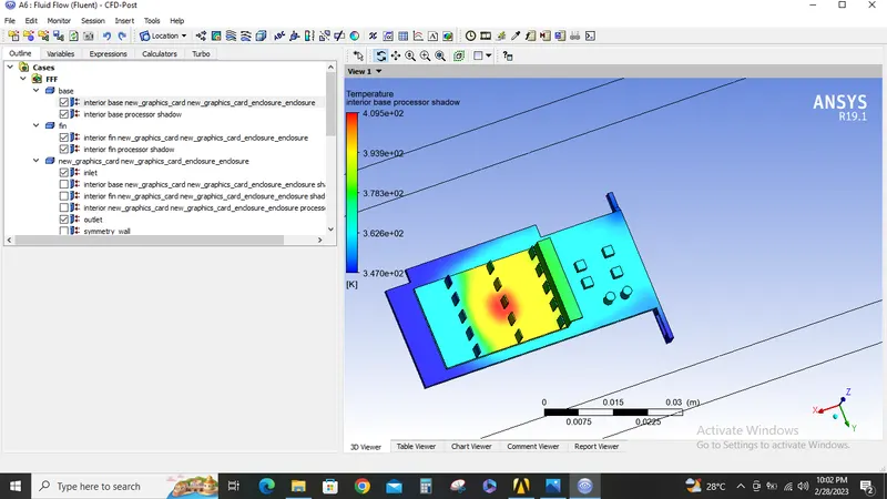
- Identify potential hotspots on the model.
Procedure:
Case1:
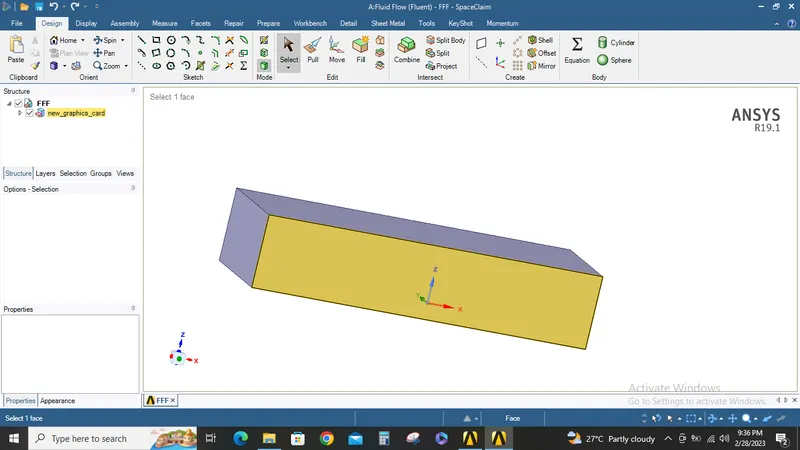
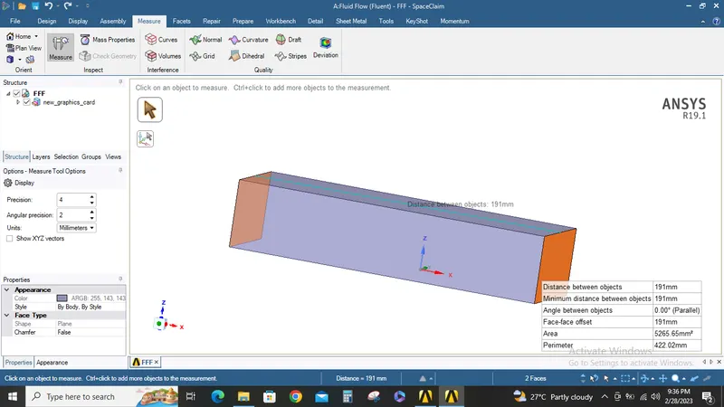
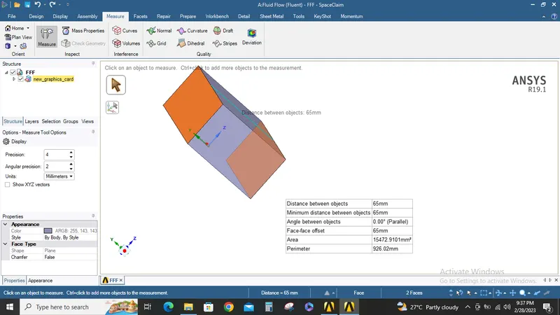
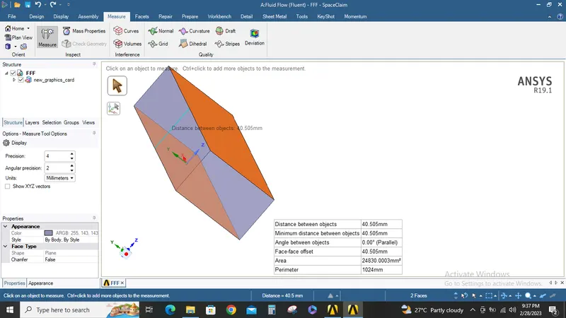
The given model is imported into space claim and the models is inspected and required dimensions for claculations are noted.
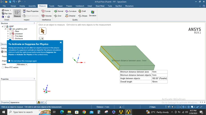
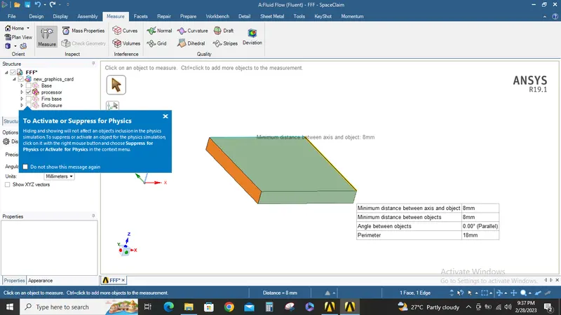
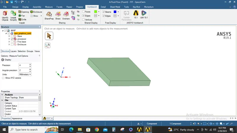
Now under workbench ribbon tab share prep and share topology option are enabled.
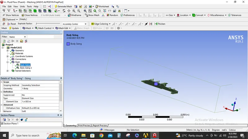
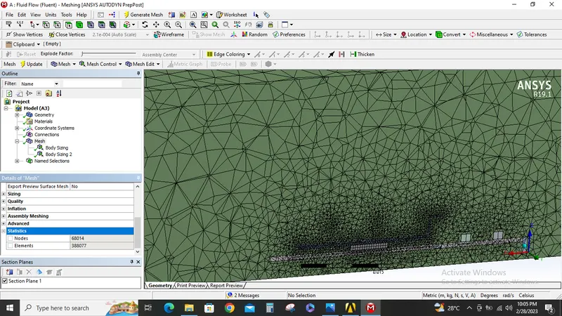
Now Mesh module is opened and graphics card is meshed with base size of 10MM and body sizing of 1MM for processor and fins.
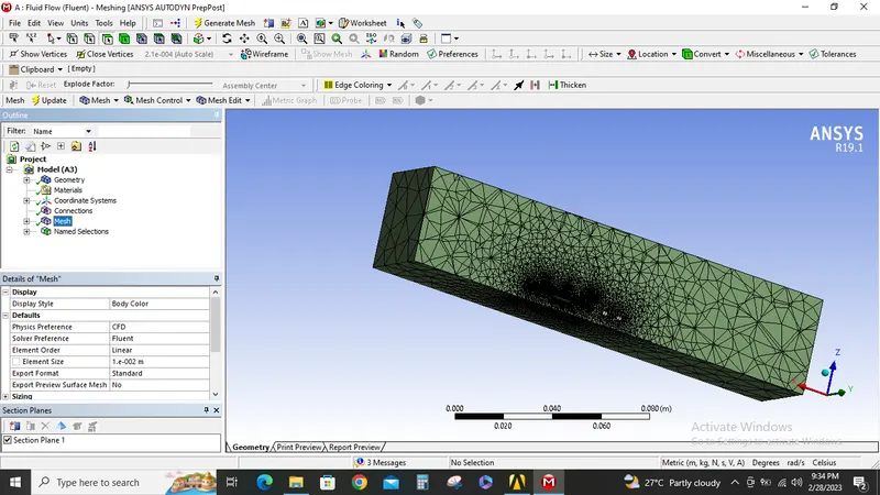
Now the Fluent is opened and mesh quality check is performed.
Steady state pressure based solver is used since velocity which will be used for the simulation is low.
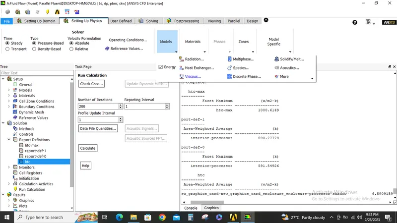
Under models energy is enabled as we are going to perform a CHT analysis.
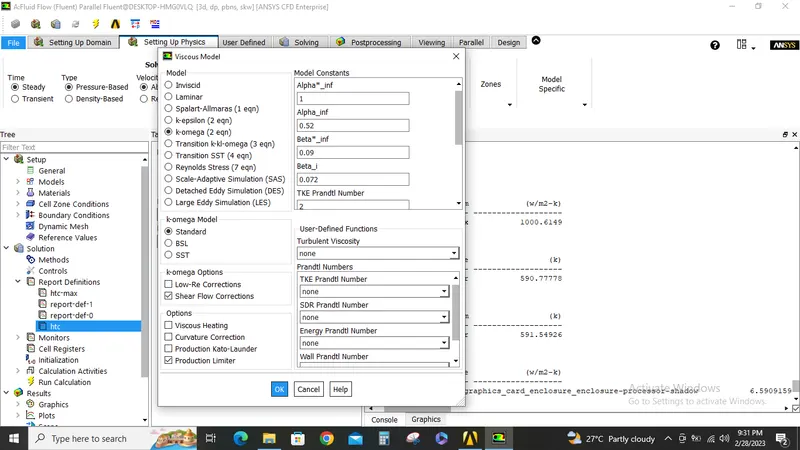
Standard K-Omega viscous model is selected.
Material for the components are selected as follows
1.Fluid-Air
2. Processor-Silicon
3. Fins-Copper
4.Base-Wood.
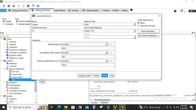
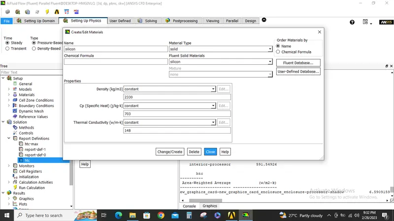
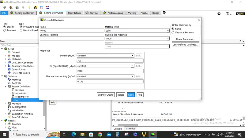
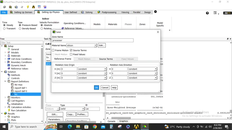
Under cell zones for fluid zone air is selected, and the appropriate materials are assigned to the respective components.
under boundary conditions inlet velocity is set to 1m/s.
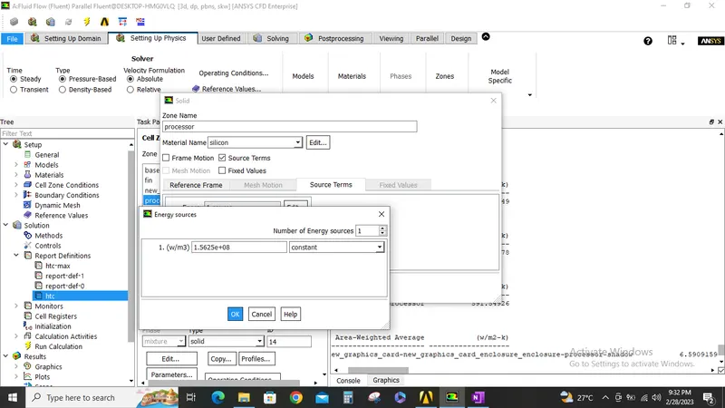
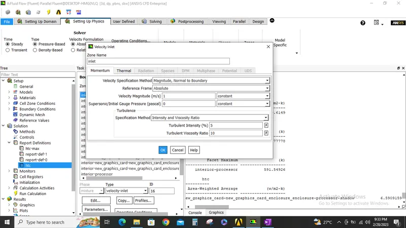
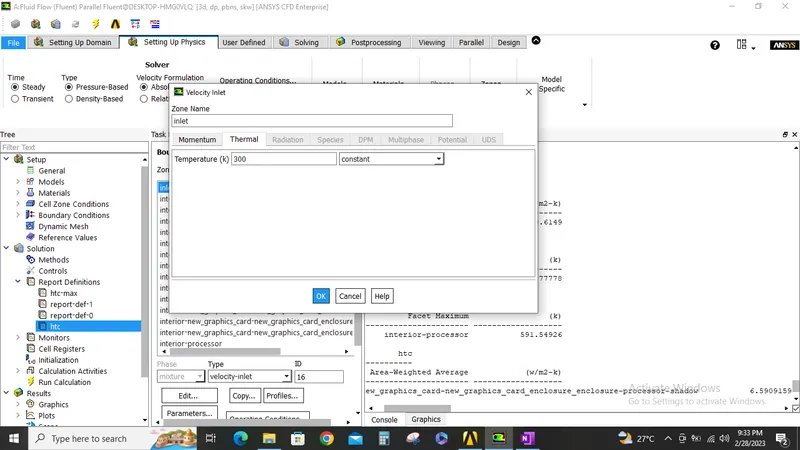
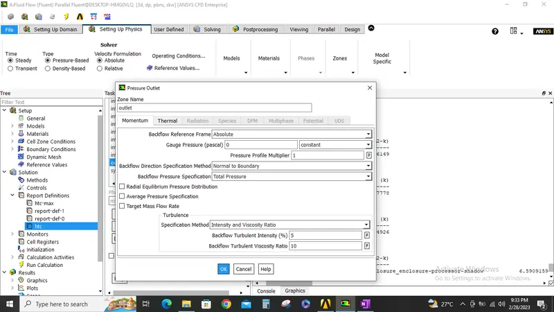
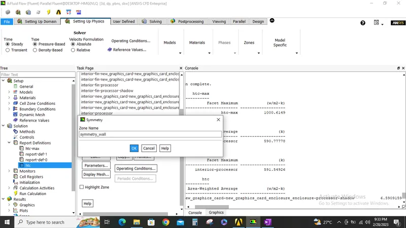
As the processor is the source of heat generation in this simulation we have given the source value of 1.5625e+08.
Volume of the processor= 0.001*0.008*0.008 m^3.
Heat generated= Watts/volume.
we have considered the TDP of the processor is 1Watt.
=1/0.000000064
=1.5625e+08 W/m^3.
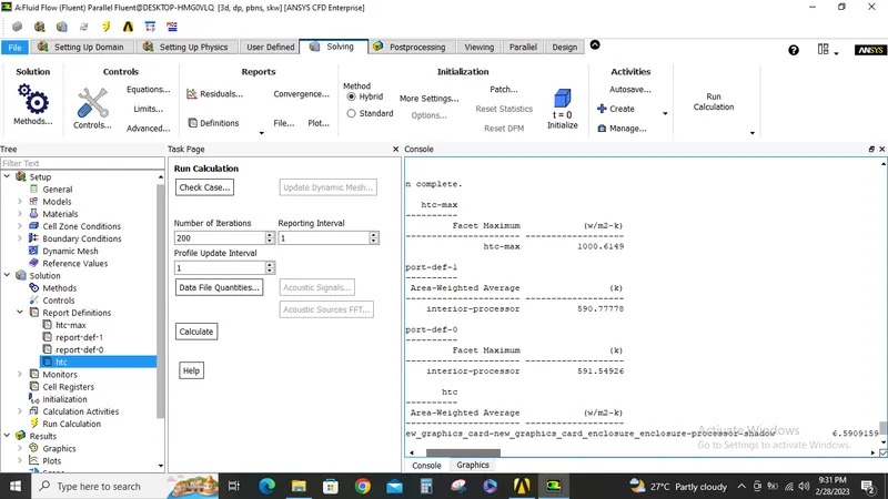
Now the solution is initialized and calculation is run for 200 iterations and the results are shown below.
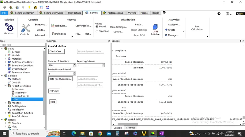
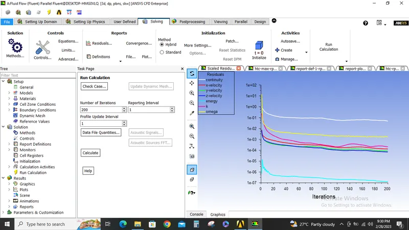
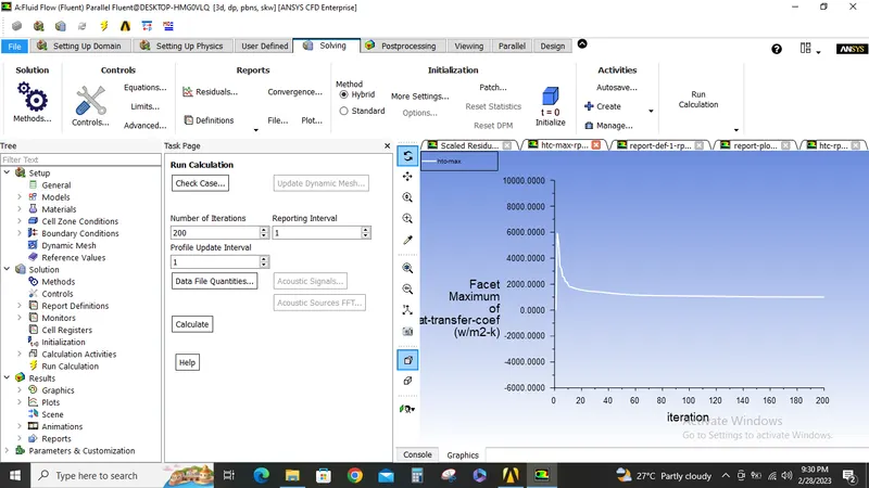
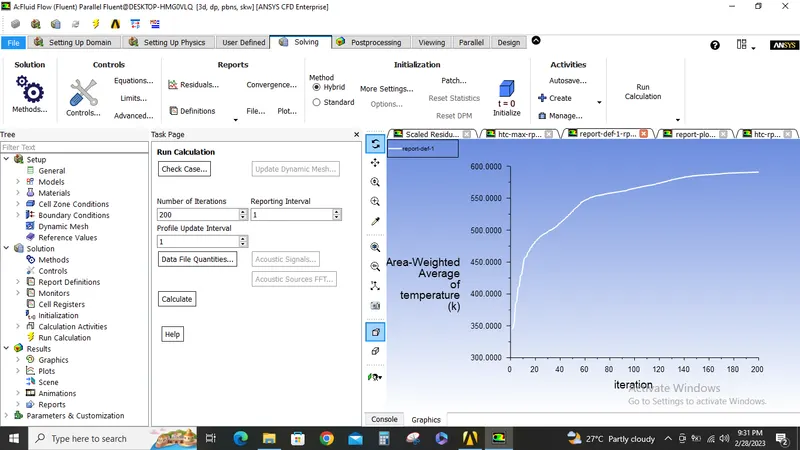
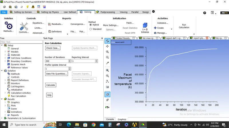
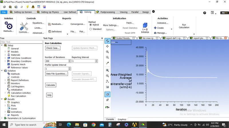
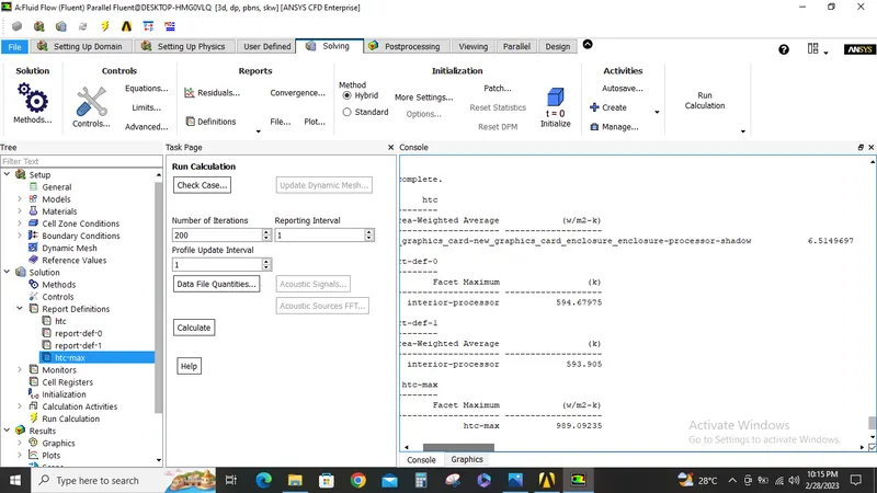
We can see from the console the Max heat transfer coefficient is 1000.61 W/M2-k.
Area weighted avg of temperature of the processor is 590 K, Max temperature is 591 K.
Area weighted avg of heat transfer coefficient is 6.5 W/M2-k.
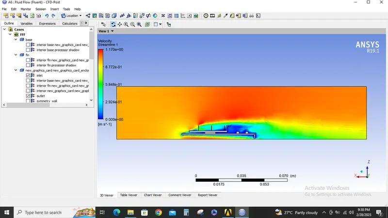
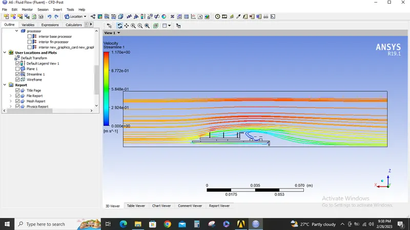
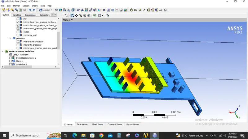
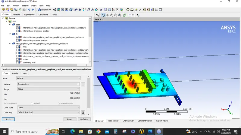
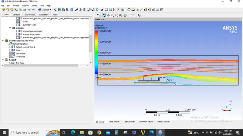
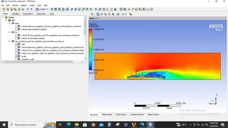
Now Hotspots on the graphics card are shown in the below screenshots from CFD post:
Case2:
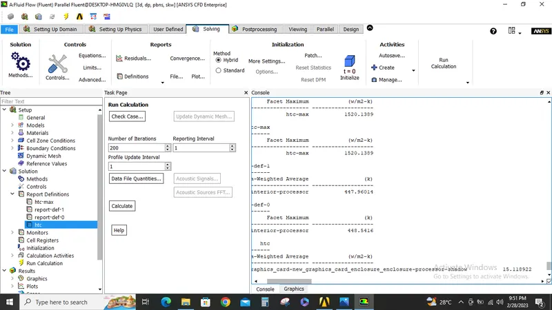
Now with the same setup described above is rerun with 3M/s velocity and the results are shown below.
Case3:
Now with the same setup described above is rerun with 5M/s velocity and the results are shown below.
Case4:
Here a mesh independent study is performed
Simulation run with velocity-1M/s and base mesh=1 MM and body sizing for processor and fins as 0.5 MM.
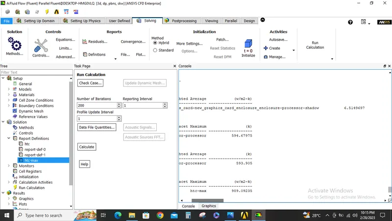
Results are shown below
| Base mesh | Body sizing Processor | Body sizing Fins | Velocity | Area weighted avg. temperature | Facet maximum temperature | HTC in W/m2-K | HTC max in W/m2-K | |
| Case 1 | 10 MM | 1MM | 1MM | 1M/S | 590 K | 591 K | 6.5 | 1000 |
| Case 2 | 10 MM | 1MM | 1MM | 3M/S | 447 K | 448 K | 15 | 1520 |
| Case 3 | 10 MM | 1MM | 1MM | 5M/S | 408 K | 409 K | 20.6 | 2097 |
| Case 4 | 1MM | 0.5MM | 0.5MM | 1M/S | 593 K | 594 K | 6.5 | 989 |
Conclusion:
1. As the velocity increases the temperature of the processor decreases also the heat transfer coefficient increases.
2. Refinement of the mesh does not improve the results but the contours looks clear, less diffused and also it takes more time to run.
Project file are available in the below link
https://drive.google.com/file/d/1FIGMbcYA08oG5nYAEJCOYSxoGaxqwVs1/view?usp=share_link