Week 6 - CHT Analysis on a Graphics card
GIVEN
Perform a steady-state conjugate heat transfer analysis on a model of a graphics card
Procedure
THE PURPOSE OF CONJUGATE HEAT TRANSFER ANALYSIS IS TO VARIOUS TEMPERATURES CONCERNING SOLIDS AND FLUIDS, DUE TO THERMAL INTERACTION BETWEEN THEM LIKE HEATING WATER IN A PAN OR HEAT TRANSFER FROM THE ENGINE TO THE RADIATOR AND RADIATOR TO ATMOSPHERIC AIR.
STEPS TO BE FOLLOWED
Step 1: Initially, start with importing the geometry to the Ansys workbench
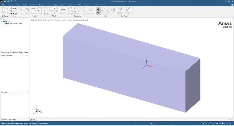
1. Encloser
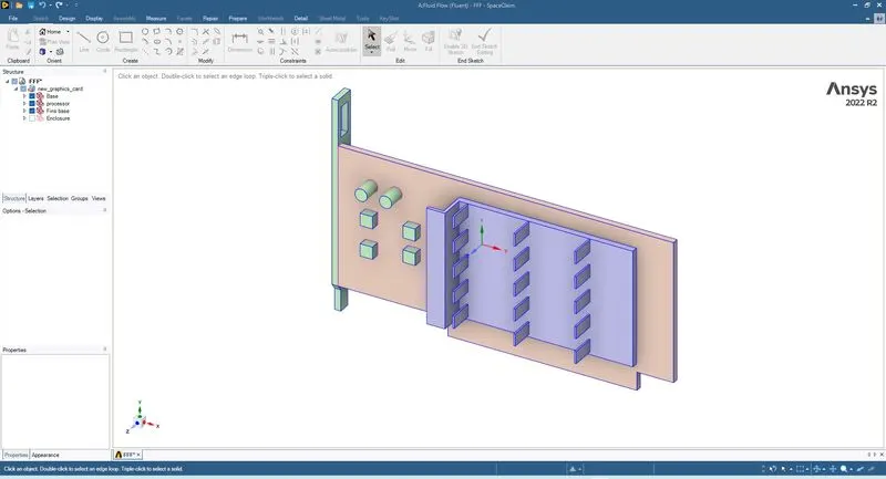
2. Fins
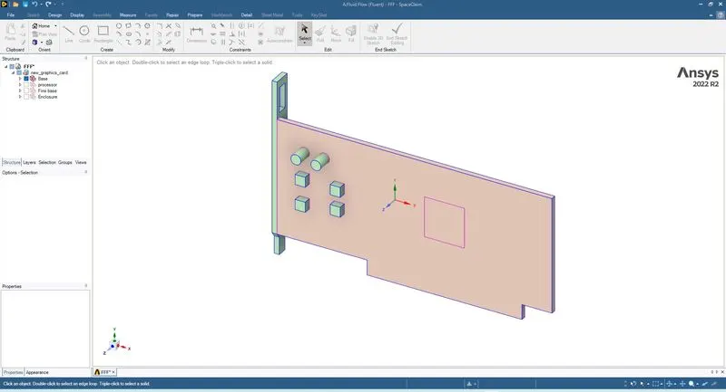
3. Base
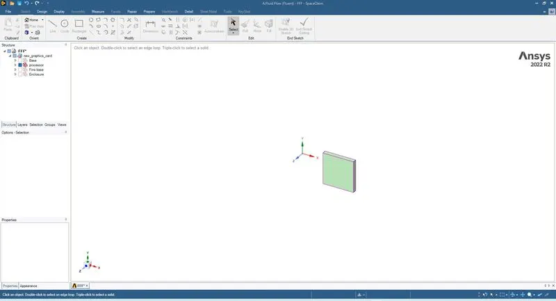
4. Processor
Step 2: From the given geometry create two kinds of mesh (coarse mesh and fine mesh) to perform grid independent study for the fine mesh analysis of their case of velocity 1m/s,3m/s and 5m/s.
1 coarse mesh
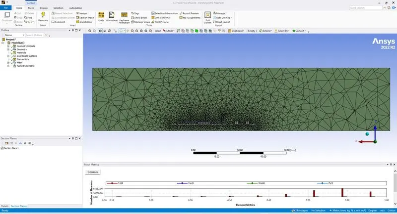
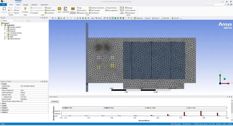
2 Fine mesh
The fine mesh has been created concerning the heat transfer that occurs from the processor to the fin and the fin to the fluid(air).
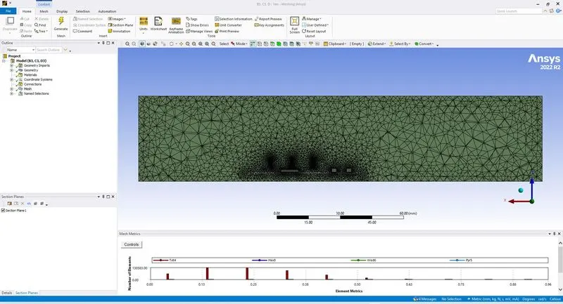
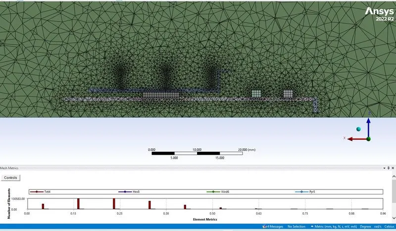
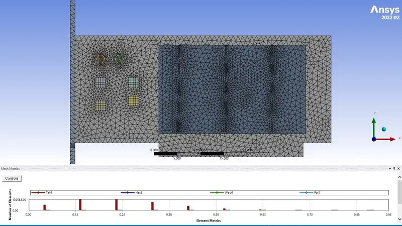
After generating the mesh, the number of nodes and elements is investigated using the statistics option. Then the mesh quality is checked by choosing the mesh matrices option in the quality section.
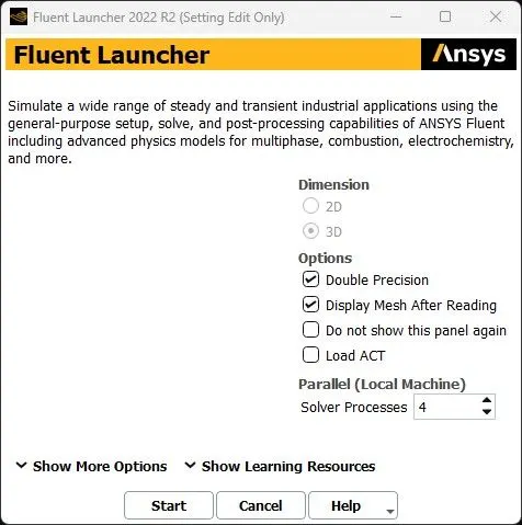
Step 3:In this step, the meshed geometric file has been imported to the fluent module and set the following conditions as follows in the fluent in solving the problem.
case 1:coarse mesh
This procedure is followed in Ansys fluent
|
SOLVER TYPE |
Pressure based |
|
VELOCITY FORMULATION |
Absolute |
|
TIME |
Steady |
|
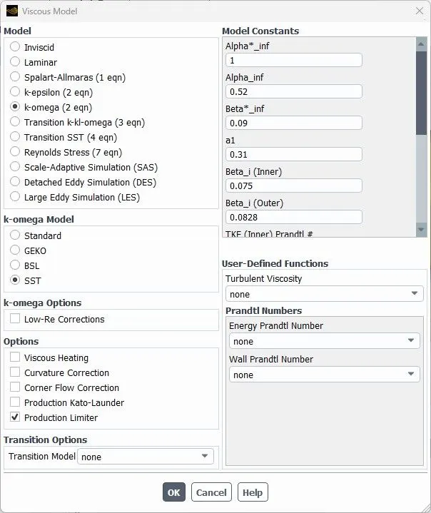
VISCOUS MODEL |
K-omega SST model and enable energy equation to solve the energy equation |
|
MATERIAL |
Fluid: air Solid: aluminium, silicon, polystyrene |
|
CELL ZONES |
Fluid flow region: air fin: Aluminium graphic processor: silicon PCB board: polystyrene |
|
BOUNDARIES (depends on the momentum ratio) |
Inlet_x (velocity inlet) Velocity magnitude:1m/s |
|
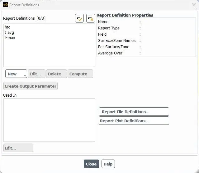
Report definition |
Area weighted average of temperature on the processor Maximum temperature of temperature on the processor HTC on the processor |
the hybrid scheme is used for the initialization

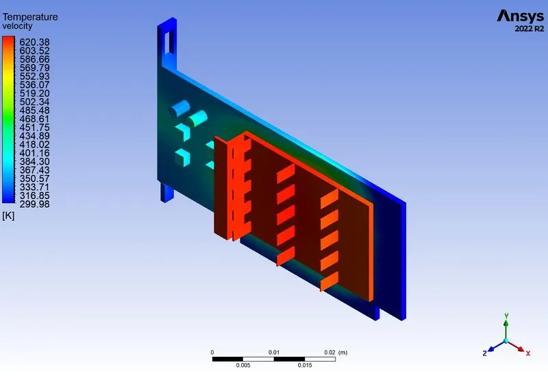
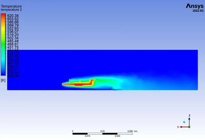
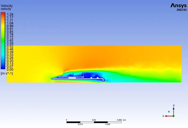
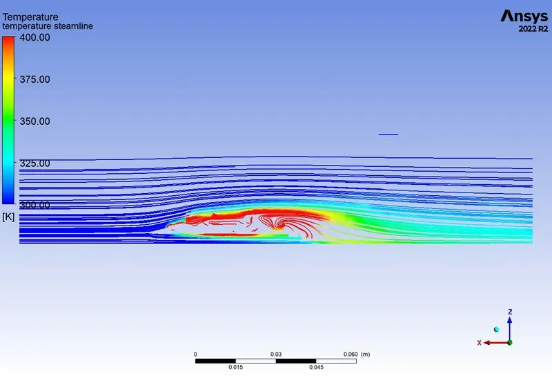
Results for coarse mesh
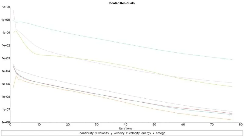
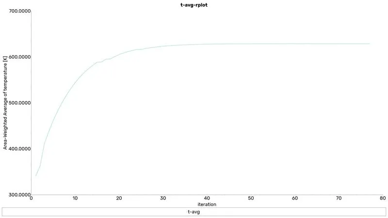
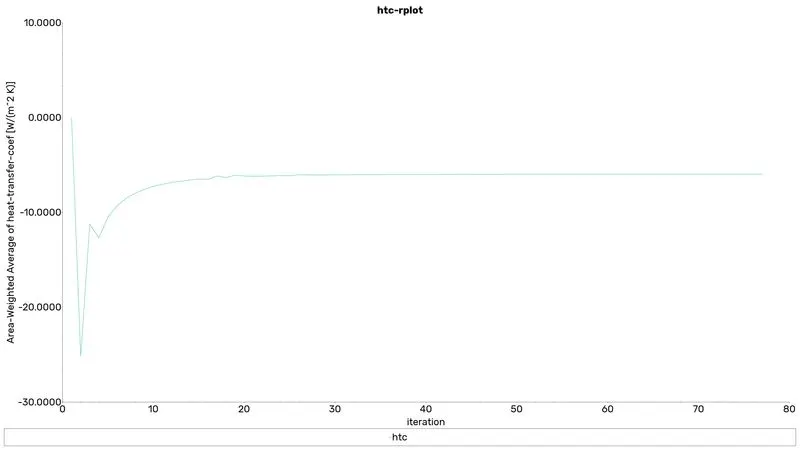
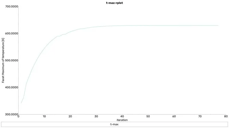
contour plots
streamline plot
case 2:Fine mesh
In fine mesh, I followed a parametric study to analyse three velocities of the flow
This procedure is followed in Ansys fluent
|
SOLVER TYPE |
Pressure based |
|
VELOCITY FORMULATION |
Absolute |
|
TIME |
Steady |
|
VISCOUS MODEL |
K-omega SST model and enable energy equation to solve the energy equation |
|
MATERIAL |
Fluid: air Solid: aluminium, silicon, polystyrene |
|
CELL ZONES |
Fluid flow region: air fin: Aluminium graphic processor: silicon PCB board: polystyrene |
|
BOUNDARIES (depends on the momentum ratio) |
Inlet_x (velocity inlet) Velocity magnitude: parametric input |
|
Report definition |
Area weighted average of temperature on the processor Maximum temperature of temperature on the processor HTC on the processor |
the hybrid scheme is used for the initialization
Results for coarse mesh
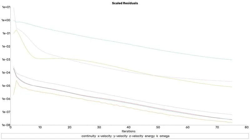
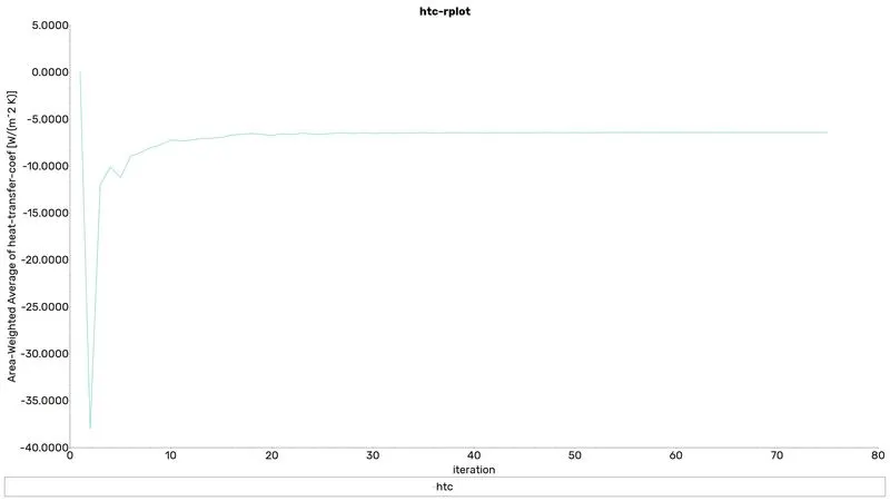
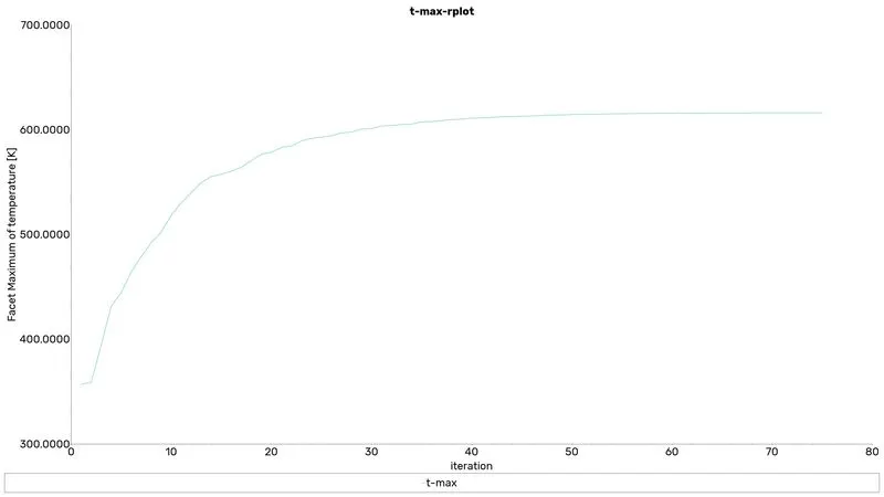
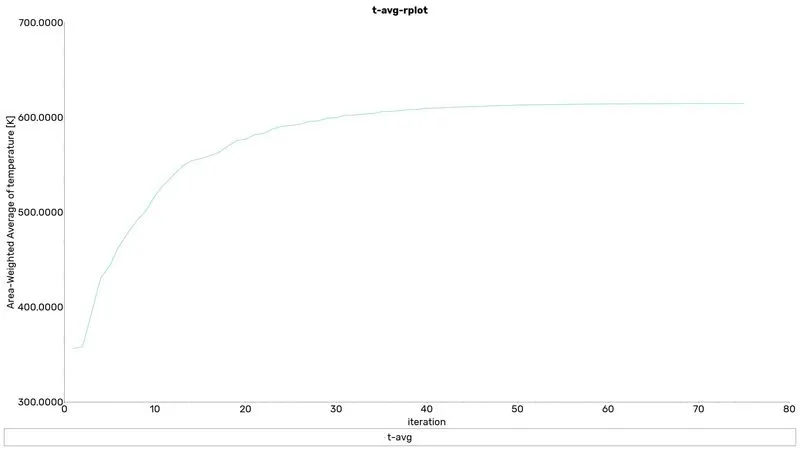
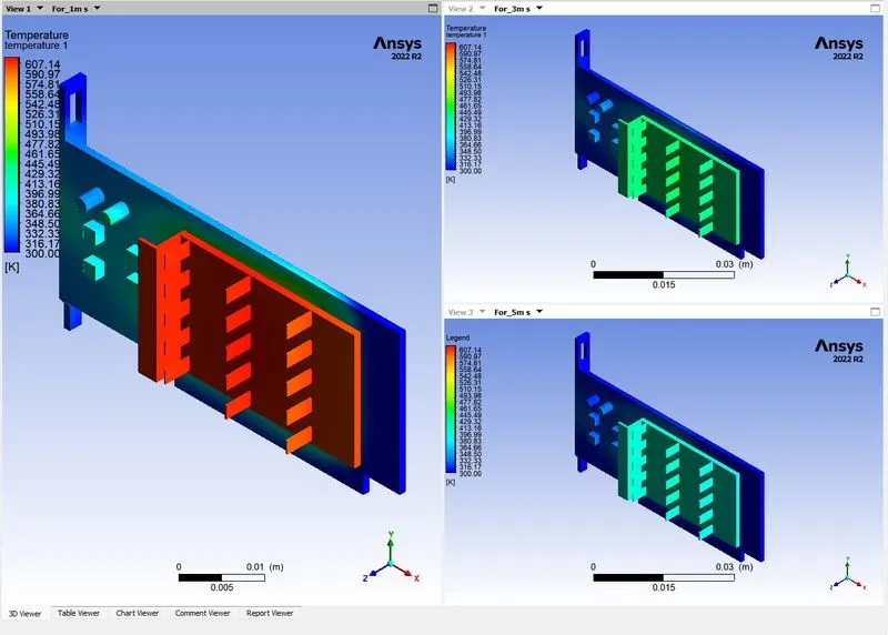
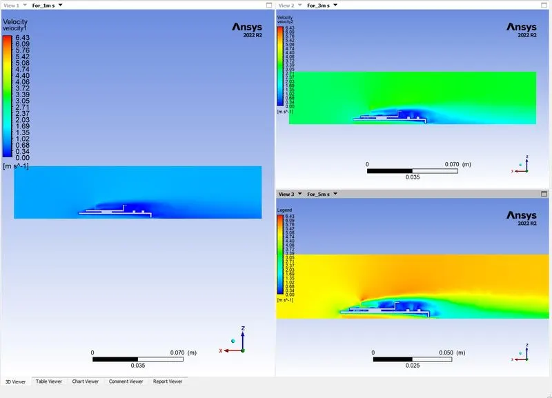
contour plot

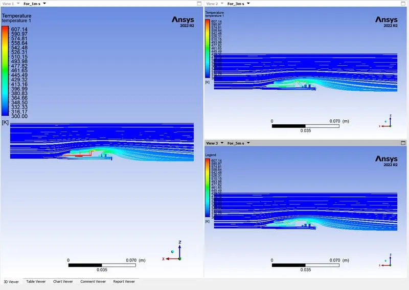
streamlines
SOLUTION DISCUSSION
1. compared to the course mesh refined mesh gives the best result comparatively.
2. When we increase the velocity of the flow the mass flow rate of air increases and takes more amount of heat from the fins'
3. The Maximum temperature depends on the velocity of the inlet air. The more the velocity less the temperature of the graphic processor.
4. The potential hotspot for the graphics card is the processor.
| Inlet_velocity (m/s) | T_avg (k) | T_max (k) | HTC (W m^-2 K^-1) |
| 1 | 614.84305 | 616.30487 | -6.4150846 |
| 3 | 447.64305 | 448.98923 | -11.269007 |
| 5 | 407.28722 | 408.63297 | -16.672601 |