Week 6 - CHT Analysis on a Graphics card
CHT Analysis on a Graphics card
Introduction:
Computational fluid dynamics and more specifically conjugate heat transfer (CHT) analysis can accurately predict heat transfer by simultaneous solving all the relevant solid and flow field heat transfer processes, for example: conduction through solids, free and forced convection in the gases/fluids and thermal radiation.
Flow chart :
- Geometry preparation
- Mesh generation
- Fluent set up
- Post-processing
Geometry:
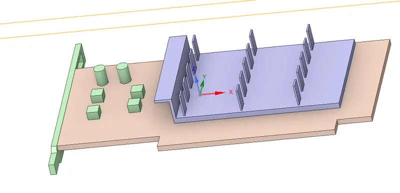
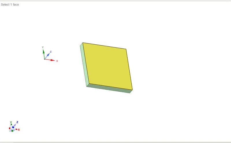
A step file is imported into ANSYS space claim. There are different components , namely:
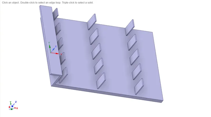
1) Fin base
2) Fins
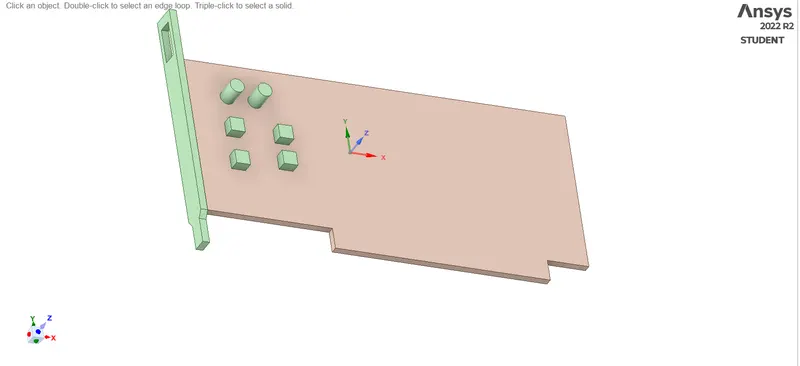
3) Processor
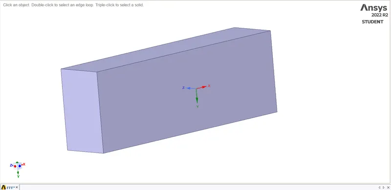
4) Enclosure
Enclosure:-
Fins :-
Fin base :-
Processor:-
Meshing:
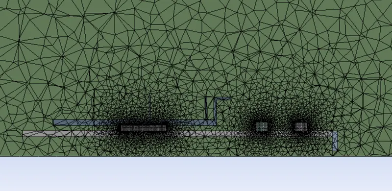
Processor is the main heat producing area. The fins and the processor are fine meshed using body sizing.
Cut plane view:-
Fluent set up:-
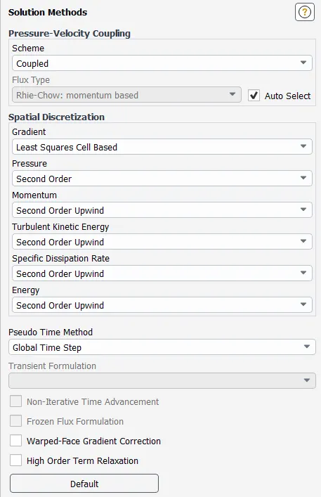
The meshed model is loaded into ANSYS Fluent. Required physics of the model is set:
Pressure based solver is used, as the flow is non compressible flow. Steady state analysis is done
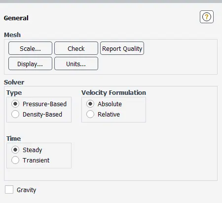
Energy is turned on.
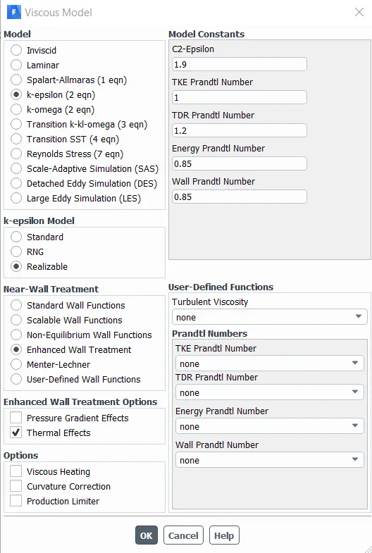
Turbulence modelling:
A turbulent flow contains wide range of turbulent eddy sizes. These are accompanied by unpredictability. Energy is transferred from larger eddies to the smaller eddies.
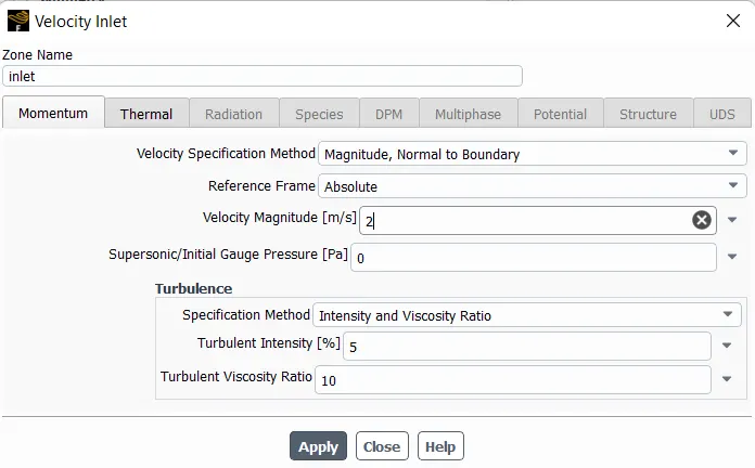
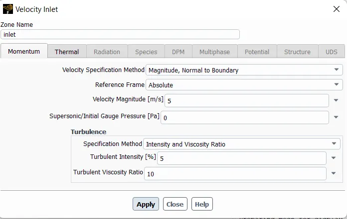
Velocity at inlet = 5m/s, 3m/s,1m/s
Post processing:
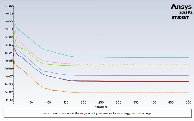
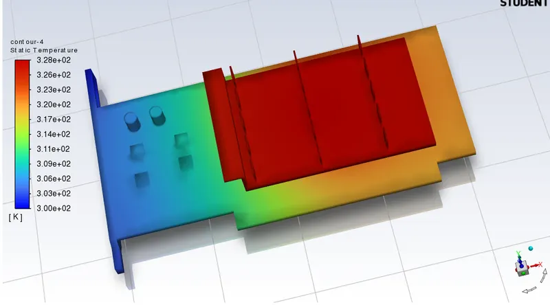
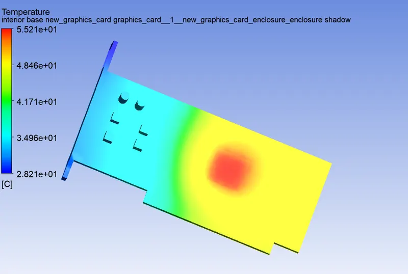
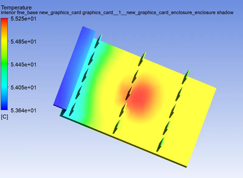
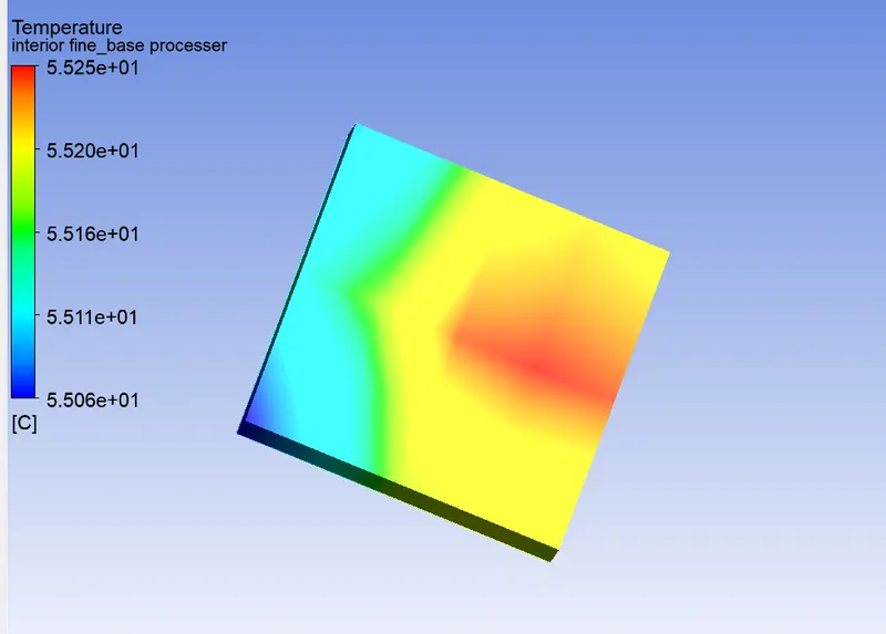
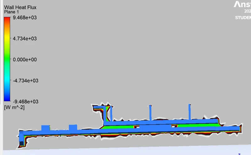
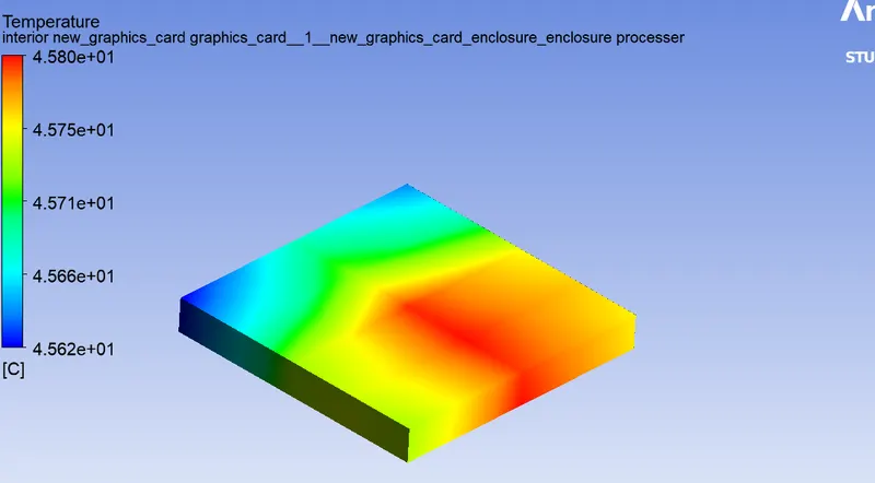
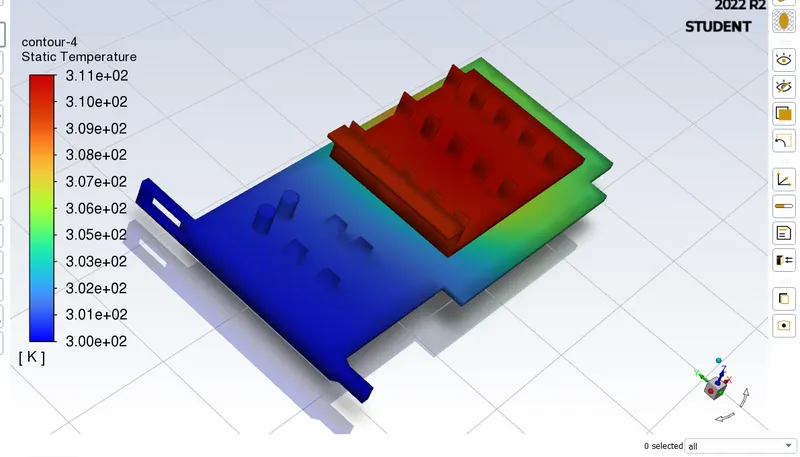
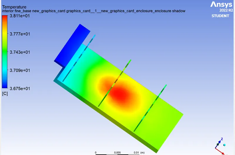
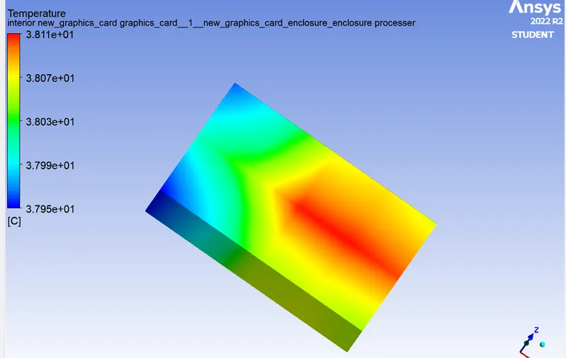
In CFD post, various contours are studied . The potential hotspots are foun out. Maximum temoerature reached also found out.
velocity 1m/s :-

Temperature Contour
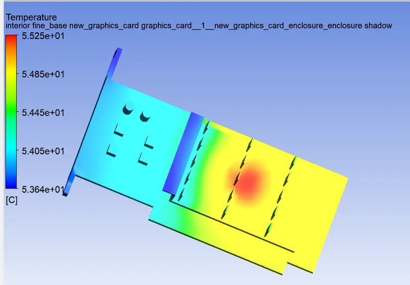
Base
Fine Base
Processer
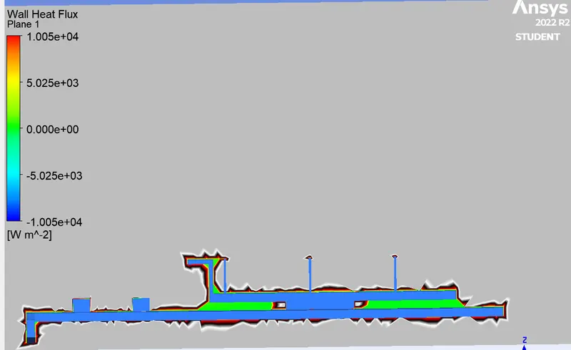
Wall heat Flux
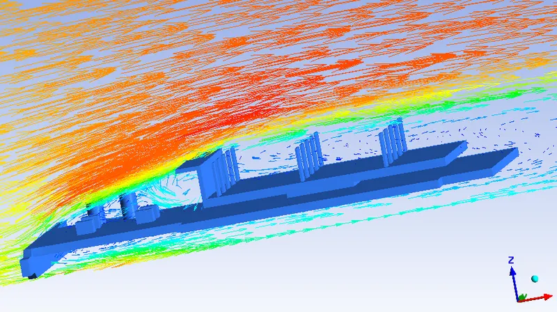
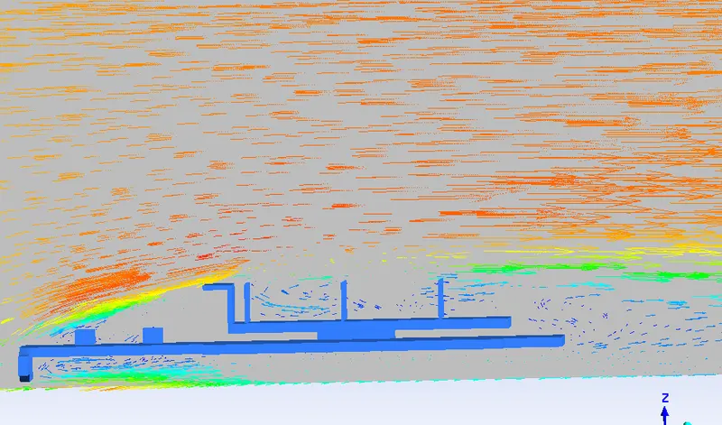
Vector plot of velocity
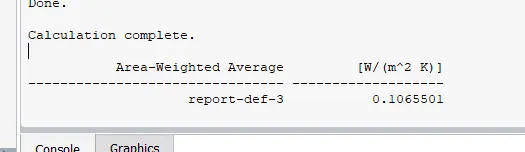
heat transfer coefficient
velocity 2m/s :-
Temperature contour
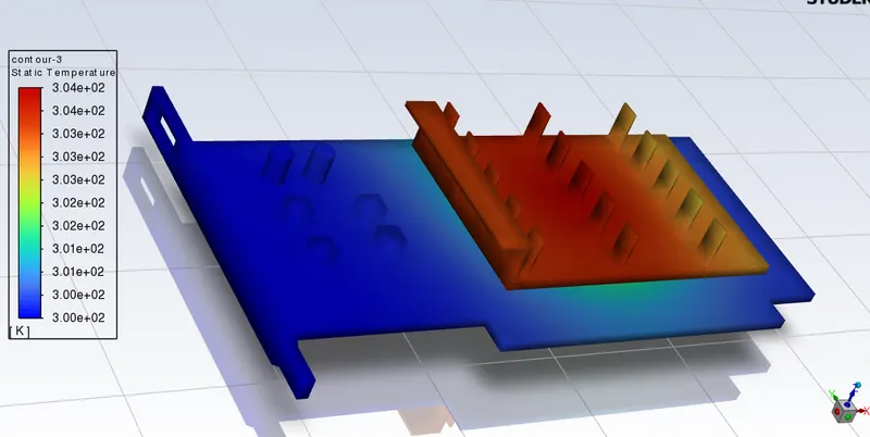
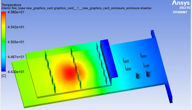
Base
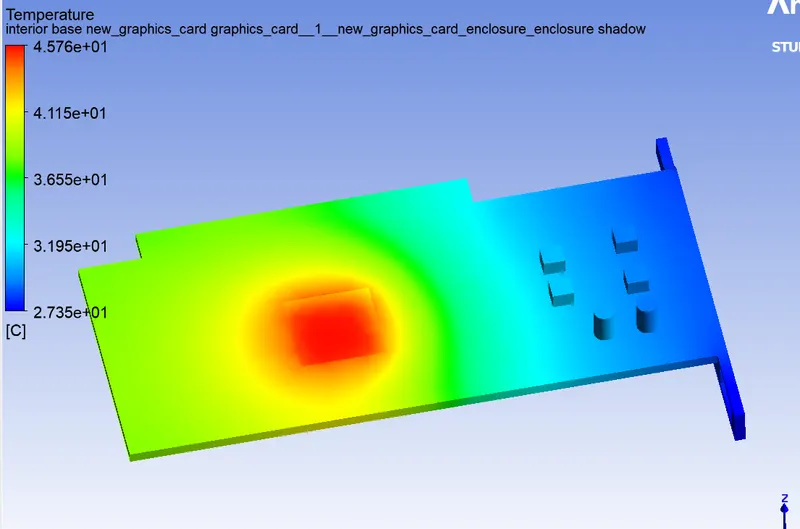
Fine Base:-
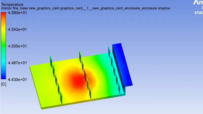
Processor :-
Wall heat Flux
Vector plot of velocity
heat transfer coefficient

velocity 5m/s :-
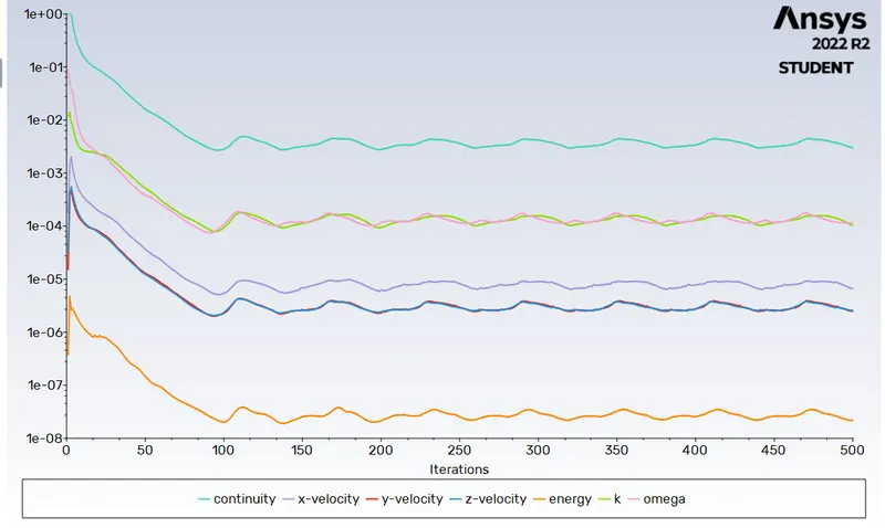
Temperature contour :-
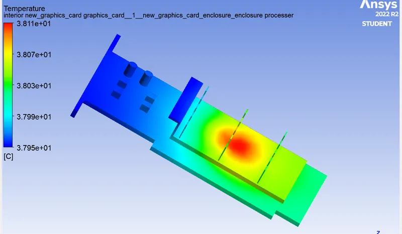
Base
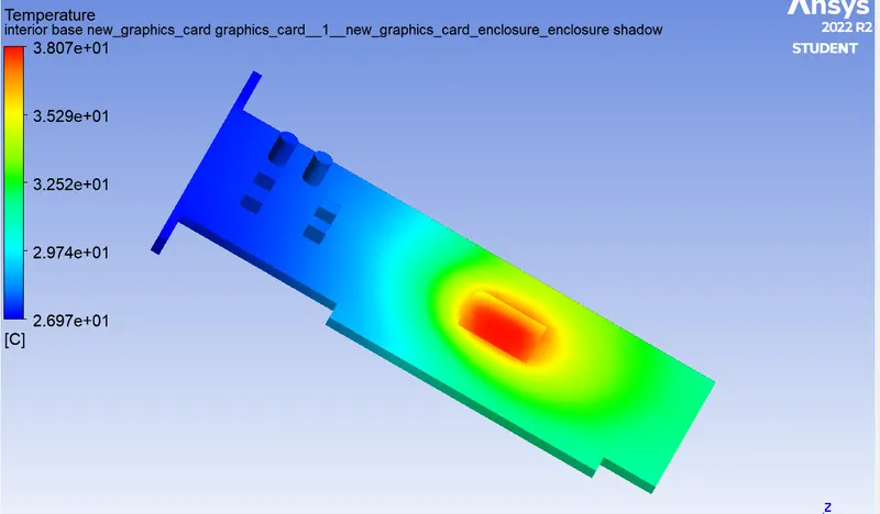
Fine Base
Processer
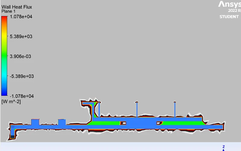
Wall heat Flux
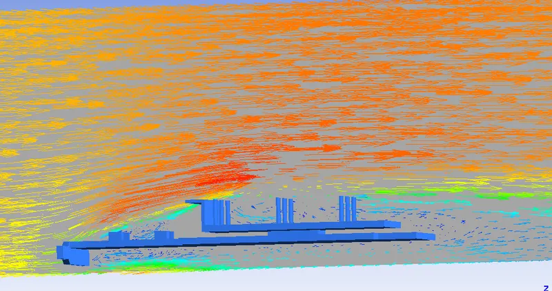
Vector plot of velocity
heat transfer coefficient

Discussion:
- The potential hotspot for the graphics card is the processor region. Maximum temperature is reached in that region
- The Maximum temperature reached depends on the velocity of air at inlet. More the velocity, less is the maximum temperature reached.
- The wall heat transfer coefficient more or less remains constant with the variatiion of the velocity of air flow.