Week 6 - CHT Analysis on a Graphics card
Aim
To perform a steady state conjugate heat transfer analysis on a model graphics card.
- Run the simulation by varying the velocity from 1m/s to 5m/s with 3 velocities and discuss the results.
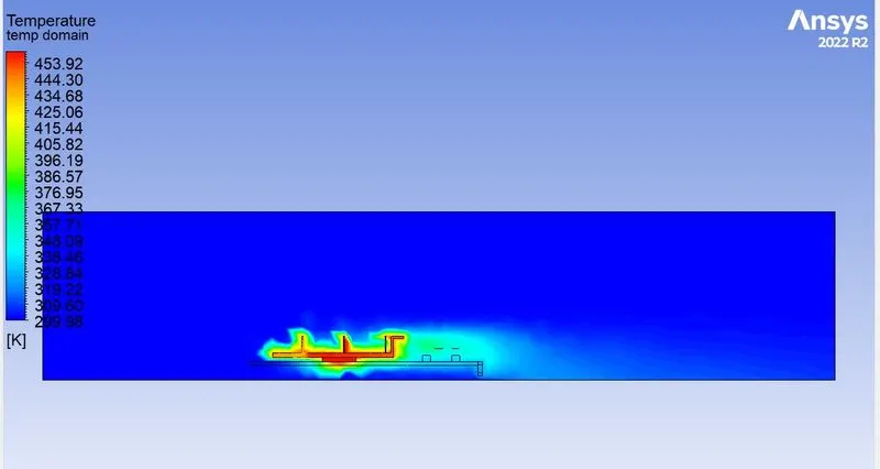
- Find out maximum temperature and heat transfer coefficient attained by the processor.
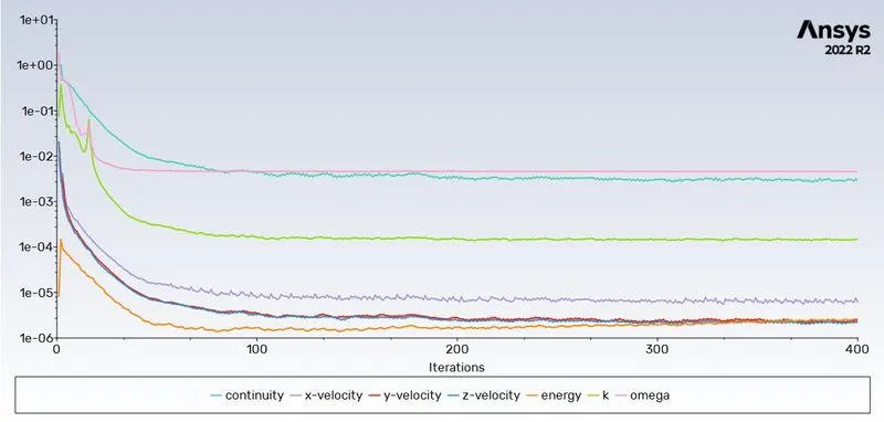
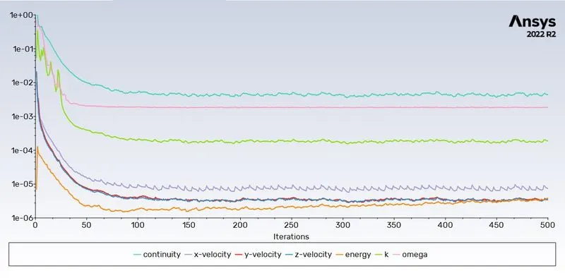
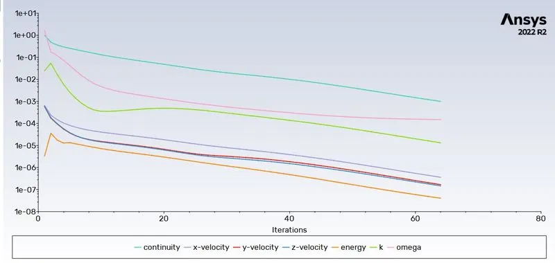
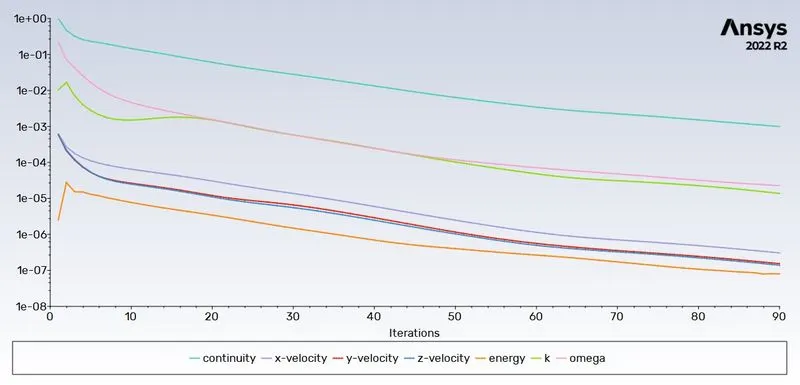
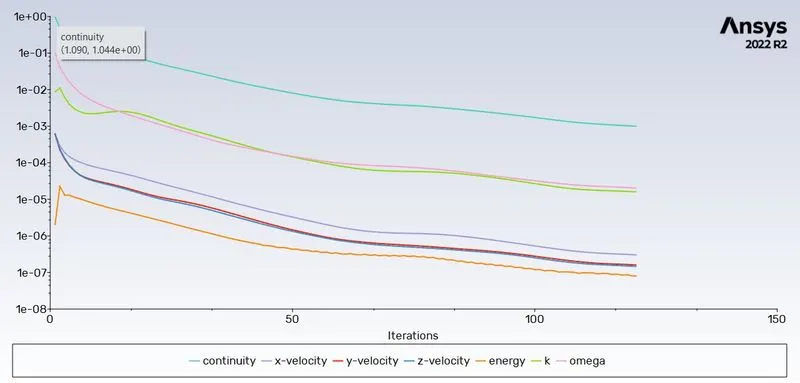
- Prove that simulation has attained convergence using suitable plots
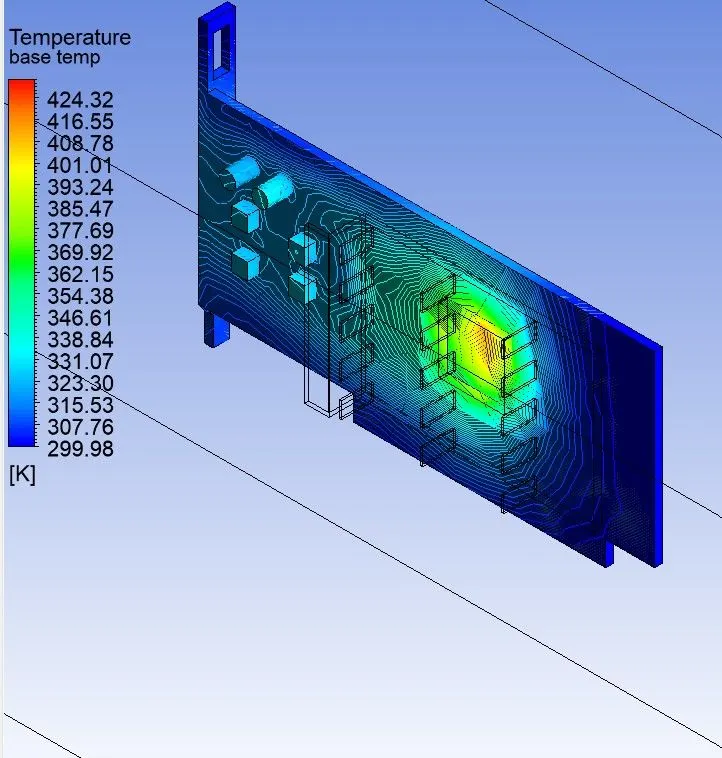
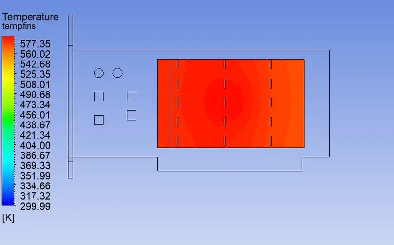
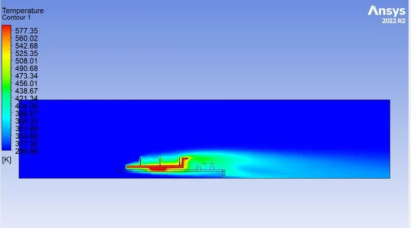
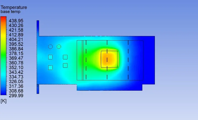
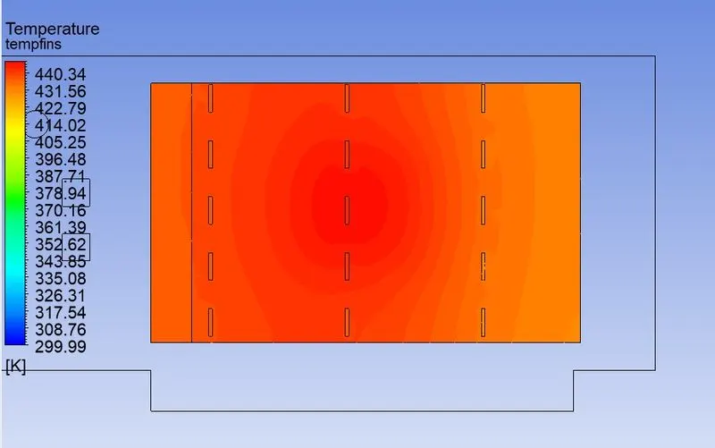
- Identify potential hotspot on the model.
Introduction and theory
Heat transfer is defined as the flow of heat energy from one region to another due to the presence of a temperature gradient. Conjugate heat transfer is a type of heat transfer between solids and fluids. This type of heat transfer includes both convection(natural and forced) and conduction. Conduction occurs in solids due to temperature gradient within the solid. This is governed by Fourier's law of heat conduction.
q=k(dt/dx)
q=heat flux(w/m2)
K=thermal conductivity
Convective heat transfer is governed by Newtons law of cooling.
q = -h*dt
h = heat transfer coefficient
Common application and uses of this thermal simulation includes electronic cooling,heat exchangers, industrial machinery etc.
Solving and modelling Approach
- Open Spaceclaim and load the prepared geometry into it. Create proper enclosure for the parts and enable share topology.
- In meshing name different parts of the geometry as well as the enclosure.
- Inlet, outlet and symmetric walls of the enclosure is named as well as parts of the graphics card like base, processor and fins.
- Create a baseline mesh for the geometry and check for any kind of interference in the mesh.
- In the solution setup a steady state, pressure based model with constant velocity formulations and k-omega SST turbulence model is used.
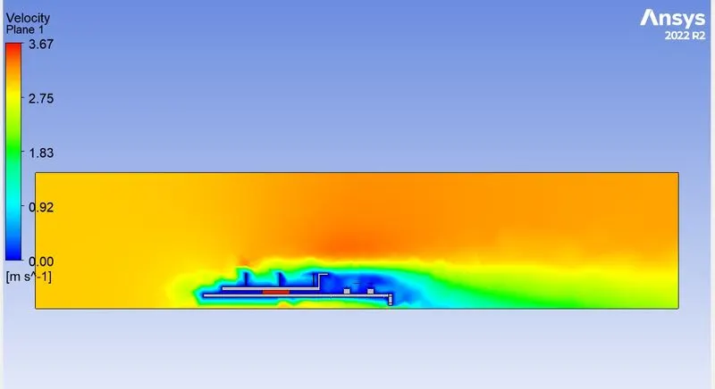
- The inlet velocity is changed from 1 m/s to 3 m/s and then to 5 m/s for three separate solutions.
- Different materials for different parts of the geometry is assigned.
- The convergence criteria is the same suggested by the software.
- The parameters that need to be calculated like heat transfer coefficient and temperature are defined at required places.
- The setup is subjected to hybrid initialization and the setup is run until convergence.
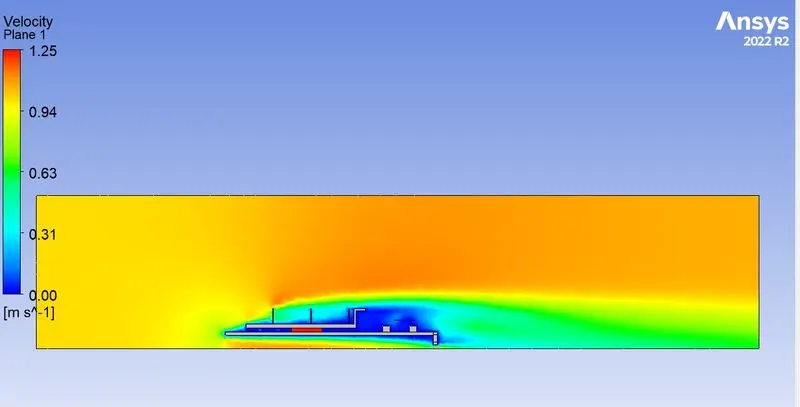
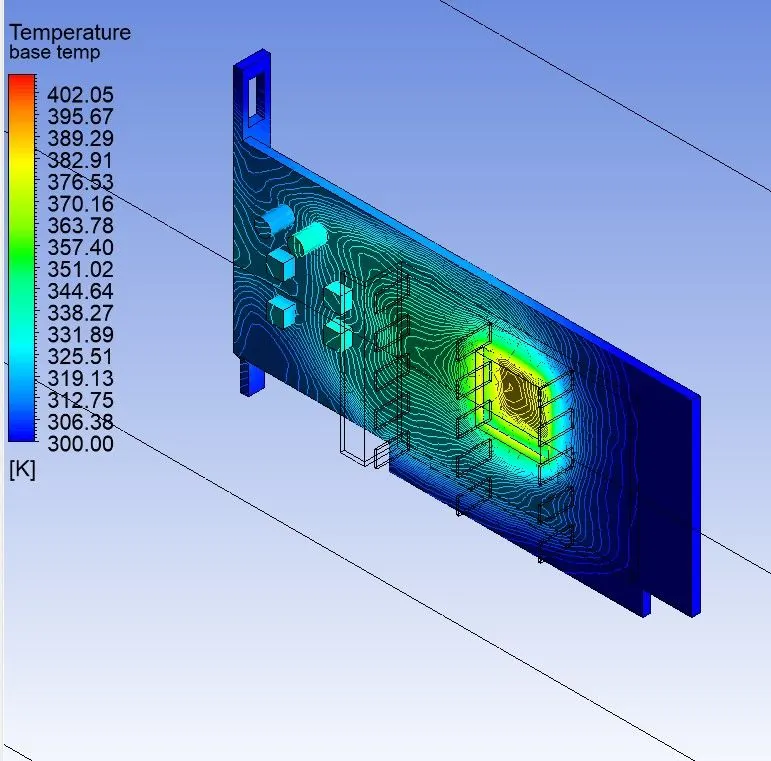
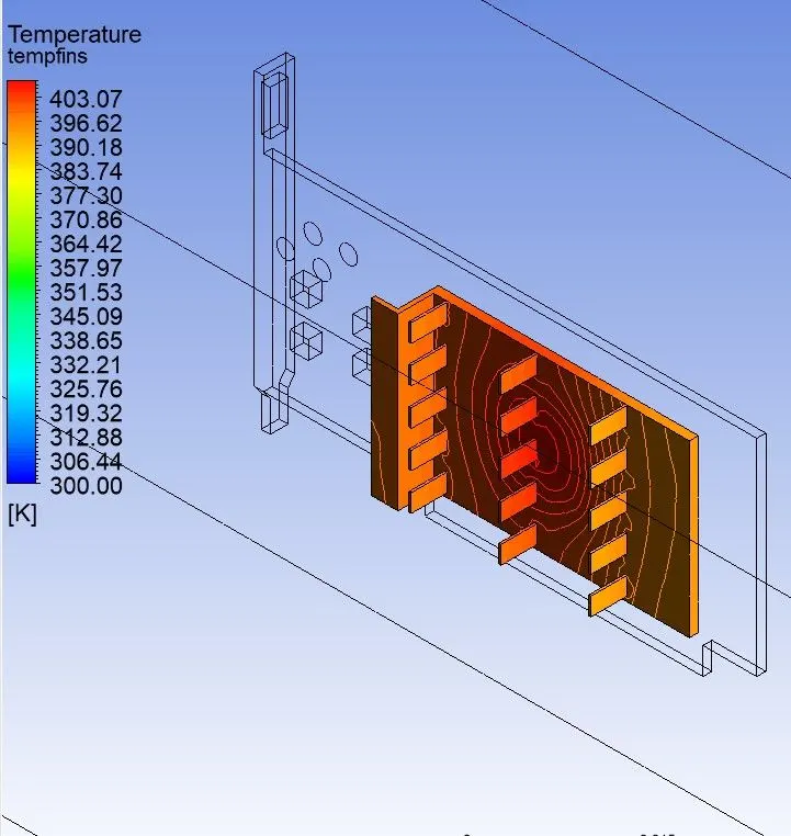
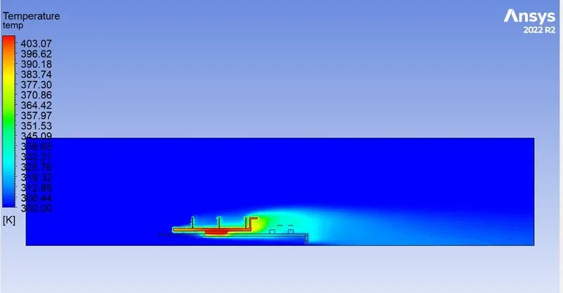
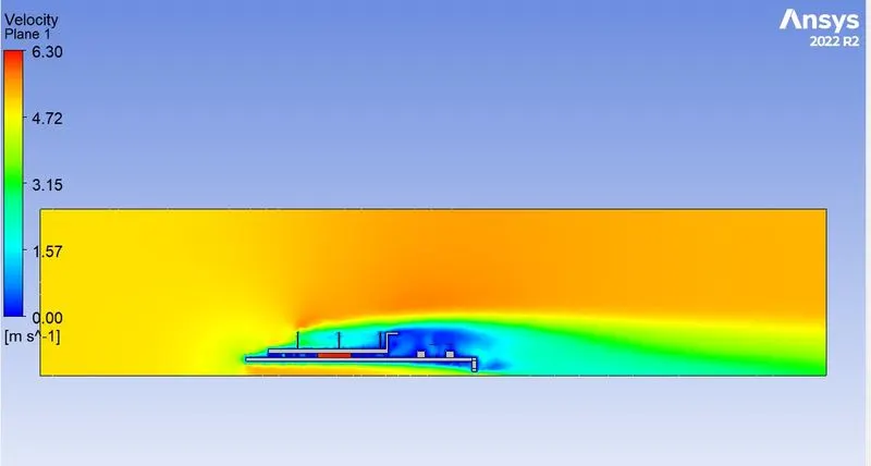
- Various contours are plotted from the results.
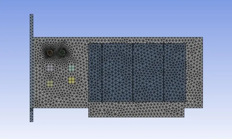
- In order to obtain a more accurate and stable result mesh is refined and the problem is solved using the above steps.
Material properties:
- Air
Density : 1.225 kg/m3
Specific heat : 1006.43 J/(Kg-K)
Thermal Conductivity : 0.0242 W/(m-K)
Viscosity : 1.7894e-5 Kg/(m-s)
- Aluminium
Part : Fins
Density : 2719 kg/m3
Specific heat : 871 J/(Kg-K)
Thermal Conductivity : 202.4 W/(m-K)
- Silicon
Part : Processor
Density : 2300 kg/m3
Specific heat : 710 J/(Kg-K)
Thermal Conductivity : 149 W/(m-K)
- PTFE (Polytetrafluoroethylene)
Part : Base
Density : 2200 kg/m3
Specific heat : 1500 J/(Kg-K)
Thermal Conductivity : 0.3 W/(m-K)
Pre-processing and solver settings
Baseline mesh:
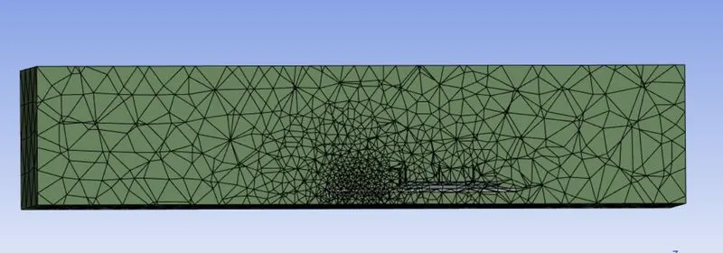


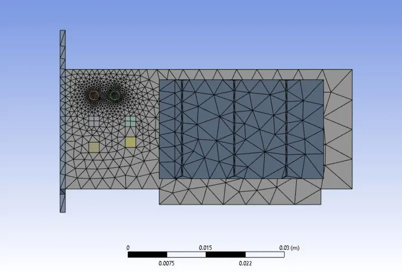
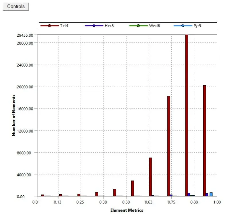
Refined mesh:
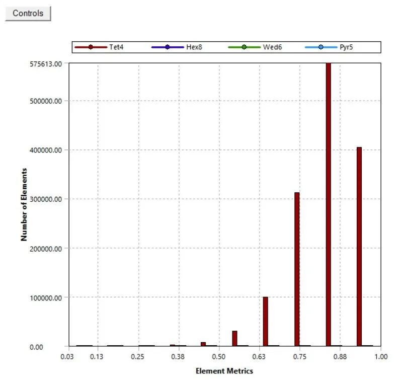

- The volumetric heat generation inside the processor is considered to be 150000000 W/m3
Results
|
Mesh |
Velocity |
Processor temp. |
Fin temperature |
HTC Processor |
HTC Fin |
|
Baseline |
1 m/s |
573.511 |
564.87989 |
0.24192381 |
18.928584 |
|
3m/s |
459.63078 |
451.12071 |
-10.445695 |
32.914623 |
|
|
5m/s |
429.58138 |
420.51632 |
-15.46891 |
40.734685 |
|
|
Refined |
1 m/s |
587.49469 |
580.51256 |
-5.3568662 |
17.76193 |
|
3 m/s |
444.81911 |
437.91921 |
-10.437642 |
35.302755 |
|
|
5 m/s |
406.04042 |
399.20421 |
-15.660976 |
47.915243 |
HTC- Heat transfer coefficient in W/m2K
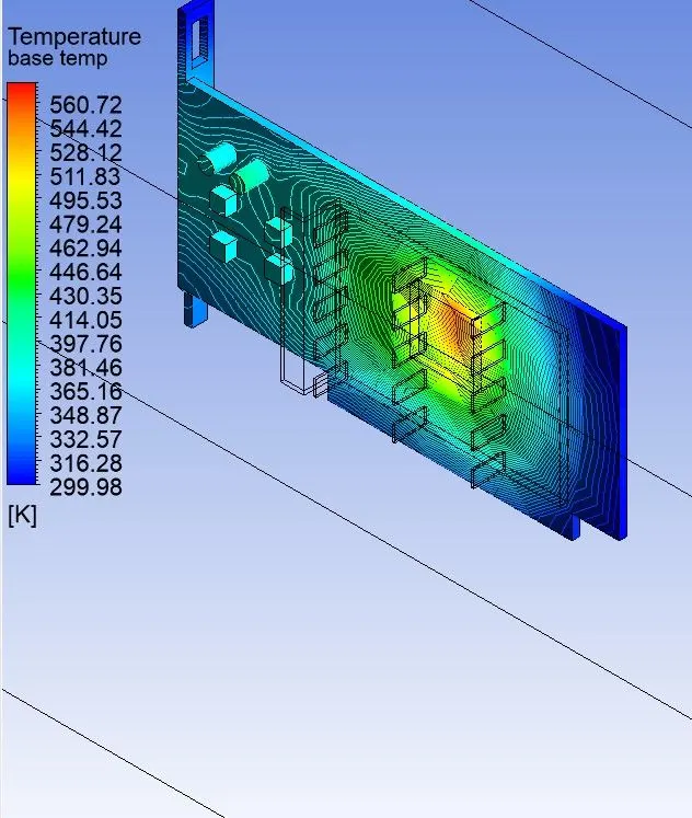
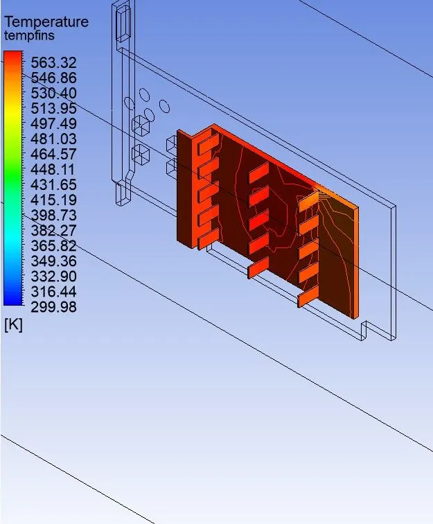
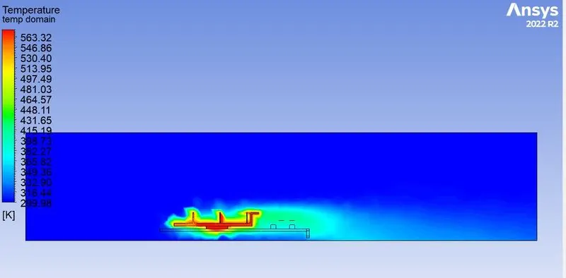
Baseline mesh:
1 m/s
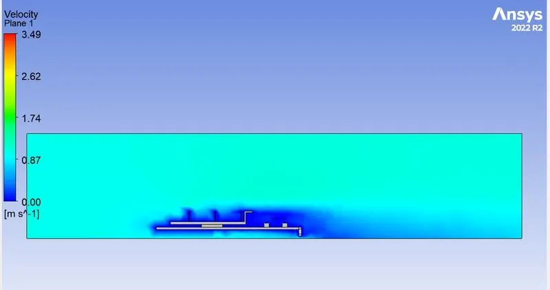
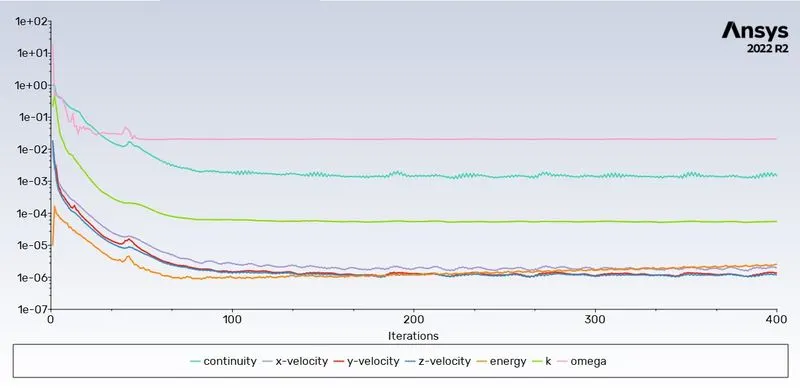
3 m/s
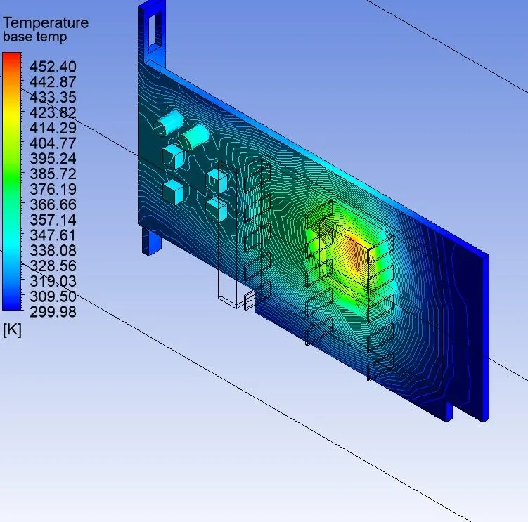
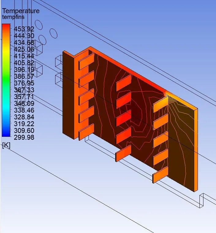
5 m/s
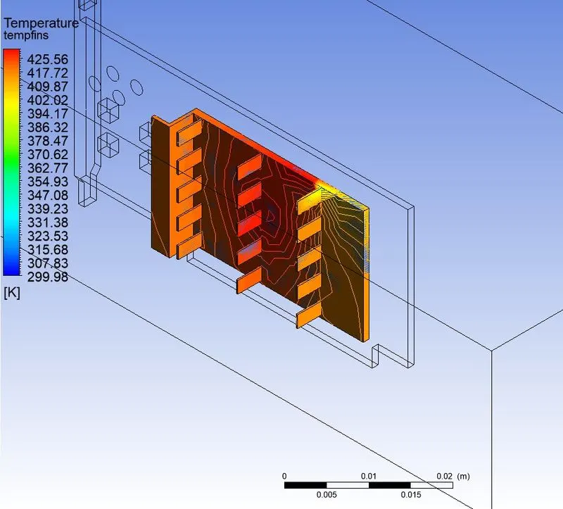
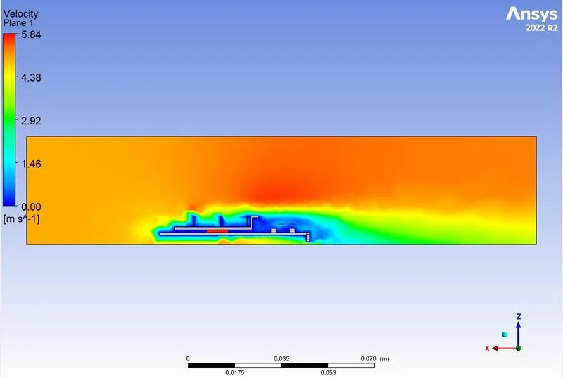
Refined mesh
1 m/s
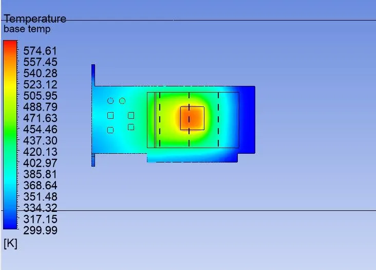
3 m/s
5 m/s
Conclusion
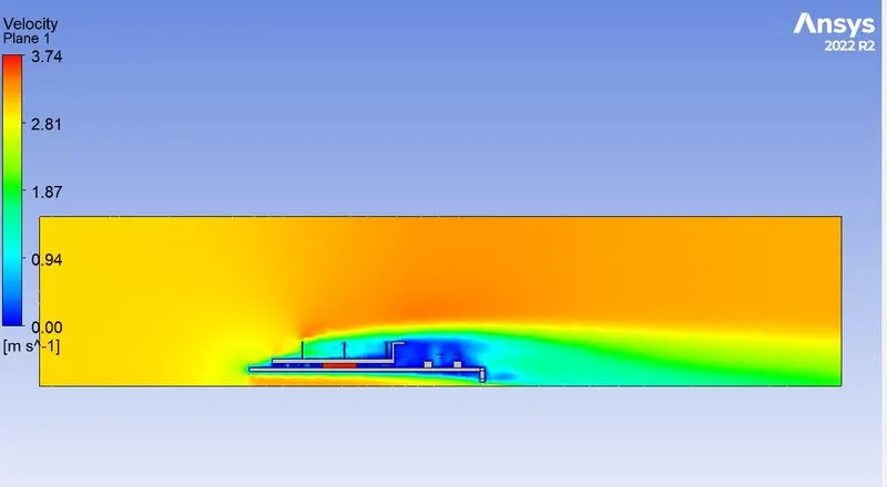
The conjugate heat transfer analysis on a graphics card is performed using Ansys Fluent and different contours are plotted. The simulation is performed for both baseline mesh as well as a refined mesh , the detail of which is mentioned above. For the baseline mesh the convergence criteria was not reached even after 500 iterations while the refined mesh gave a solution within 200 iterations. The results matches the expectation that is the temperature on the processor is getting reduced as the speed of the air flow is increased. The us of fins is effective in reducing the temperature of the processor. No potential hotspots are visible when the speed of the air is 5 m/s. The heat transfer coefficient as well as the temperature is tabulated.