Week 6 - CHT Analysis on a Graphics card
AIM: Perform a steady-state conjugate heat transfer analysis on a model of a graphics card and Run the simulation by varying the velocity from 1m/sec to 5m/sec for at least 3 velocities and Find out the maximum temperature and heat transfer coefficient attained by the processor.
OBJECTIVES:
- Run the simulation by varying the velocity from 1m/sec to 5m/sec for at least 3 velocities and discuss the results.
- Find out the maximum temperature and heat transfer coefficient attained by the processor.
- Prove that the simulation has achieved convergence with appropriate images and plots.
- Identify potential hotspots on the model.
INTRODUCTION:
Conjugate heat transfer is defined as the heat transfer between two domains by exchange of thermal energy. for a system the thermal energy available is defined by its temperature and the movement of thermal energy is defined by its heat flux through the outer walls. heat transfer in solid happens through conduction and the wall by convection and in fluids through convection and radiation.
GRAPHICS CARD:
The purpose of a graphics cards is to render graphics. Without a graphics card, your computer can not display any information, let alone function how you need it. To simplify it, the GPU takes data from the processor and works with software to determine where the graphics card places pixels on the screen.
THEORY:
To do the simulation of graphic card for the purpose of to maintain minimum temperature of graphic card to run safe. this simulation is for to supply air to cool the graphics card with required velocity of air. During the working of graphic card it generates lot of heat in processor to maintain the low temperature we will install a heat sink fan on the graphics card to maintain the air velosity according to the velocity required heat sink to cool the processor. To do the simulation with different velocities and mesh independent study on graaphics card.
SLOVING AND MODELLING APPROACH:
1.First i open the workbench and then i drag the anasys fluent into the work space. then i open then geometry on the popup and i open the spaceclaim and import the geometry into the spaceclaim.
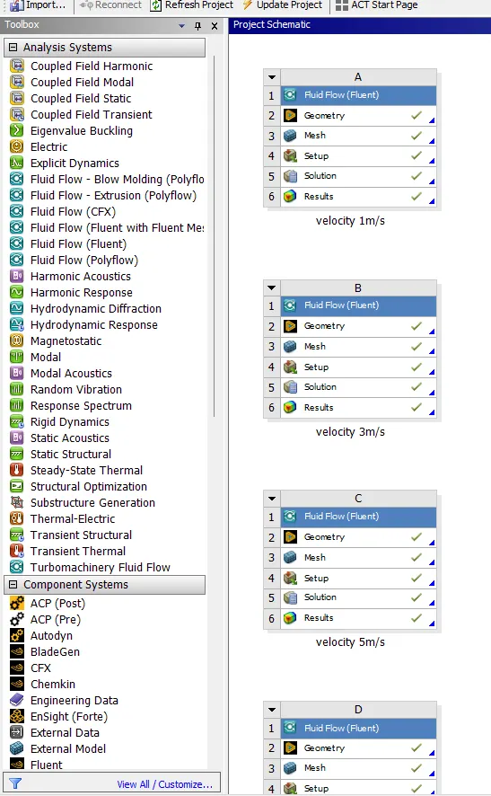
fig: main setup.
2.here the model is already to mesh.there no geometry cleanup in the model it is already with the enclosure.here i used the share tropology. then i went to the meshing part.
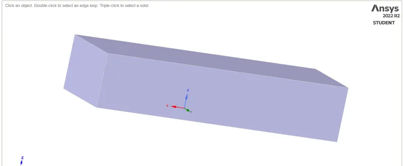
fig:graphics card with enclosure.
3. here i used the mesh size of 8mm for the enclosure and the for fins and board size of 1mm. To give the meshing i used the body meshing for the fine & processor and then i used the multizone to apply the different meshsize the i meshed the board by body meshing only.
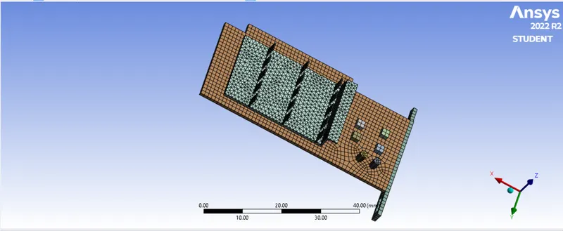
fig: meshed graphics card.
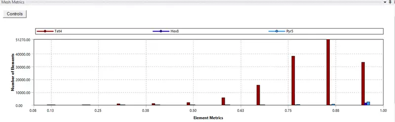
fig: mesh quality.
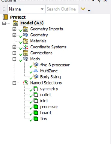
fig: mesh setup.
4.then i went to give the name selection of the each and every part. by used box and single selection method. they are symmetry, outlet,inlet , processor, fins and board.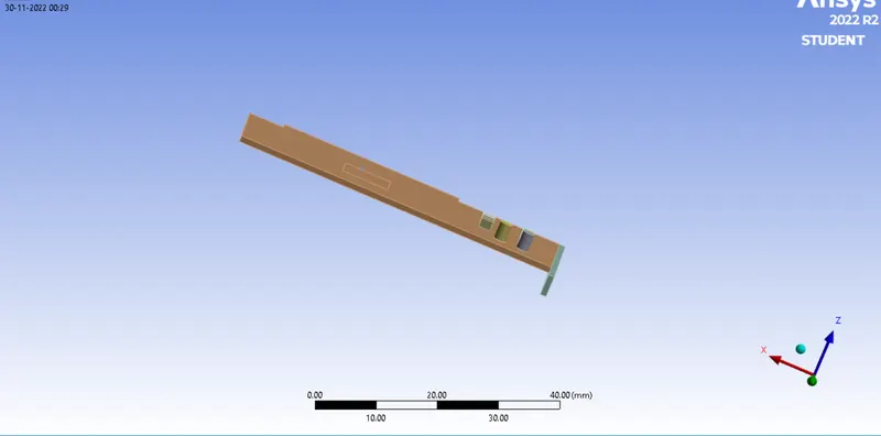
fig: board.
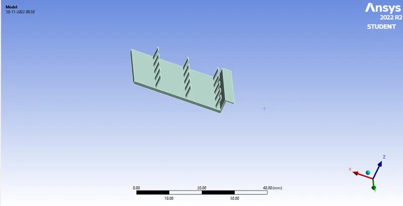
fig: fins.

fig: processor
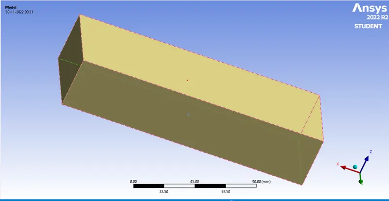
fig: symmetry.
CASE 1
velocity 1m/s , mesh size 8mm, precessor mesh size 1mm.
CASE 2
velocity 3m/s , mesh size 8mm, precessor mesh size 1mm.
CASE 3
velocity 5m/s , mesh size 8mm, precessor mesh size 1mm.
CASE 4
velocity 5m/s , mesh size 7.5mm, precessor mesh size 0.75mm.
CASE 5
velocity 5m/s , mesh size 6.5mm, precessor mesh size 0.5mm.
5. then i went to the solving the simulation of the geometry by giving the input conditions according to the requirment for the simulation.
6. here i open the boundary condition to given the velocity inlet of the air, then i open the material for the each part according to the material. i went to the flunent data base to apply the material like Al, board and siliocn.
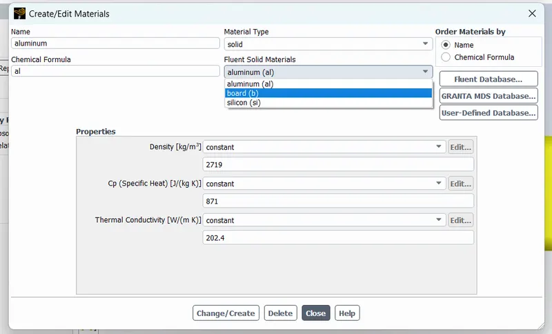
fig: material setup.
here materials
silicon:
Density = 2330 kg/m^3
Cp = 730J/(kg-K)
thermal conductivity = 153 W/(m-K)
Board:
Density = 55 kg/m^3
Cp = 1210 J/(kg-K)
thermal conductivity = 0.027 W/(m-K)
aluminum:
Density = 2719 kg/m^3
Cp = 871 J/(kg-K)
thermal conductivity = 202.4 W/(m-K)
7. here i assumed the heat dissipation rate of p= 1w
Qg =Q/V = 1/64*10^-9 W/m^3
8. then i have given the all the input condition then i initialized the simulation and i made the report for the maximum temperature of the processor, avg. temperature of the processor and htc of the processor.
9. then i contour plot of the velocity ,pressure and temperature. then i run for the simulation upto converged of the soluation.
solver setup is same procedure for the all casess
OUTPUT:
CASE 1 velocity 1m/s.
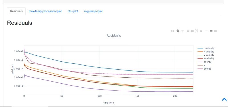
fig: Residual plot.
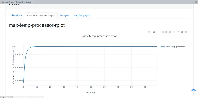
fig: max temp processor.
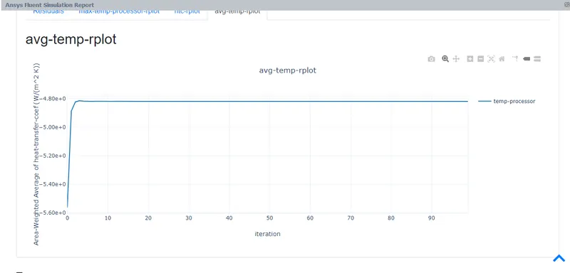
fig: Avg-temp-plot
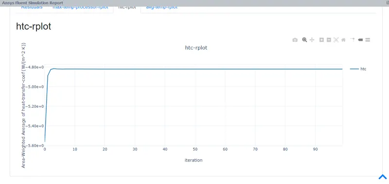
fig: htcb plot
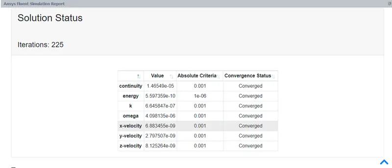
fig: converged
CASE 2 velocity 3m/s
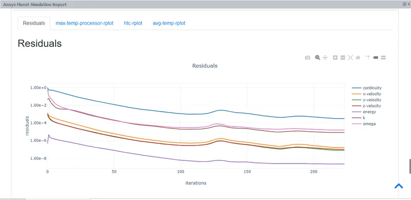
fig: residual plot
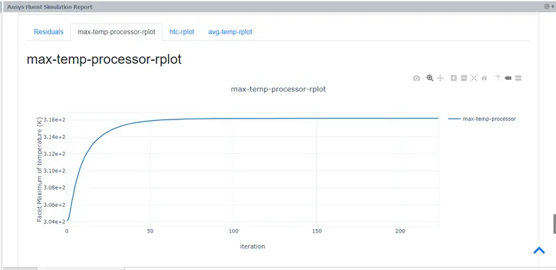
fig: max temperature plot.
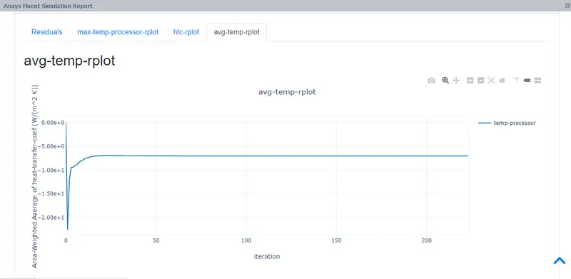
fig: Avg-temp-plot
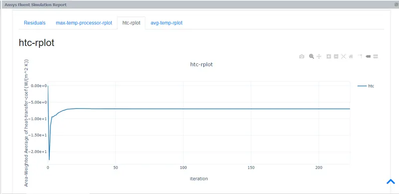
fig:htc plot
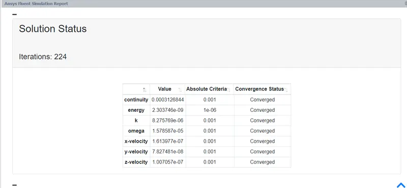
fig: converged
CASE 3 velocity 5m/s
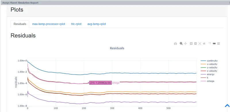
fig: residual plot
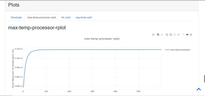
fig: max temperature
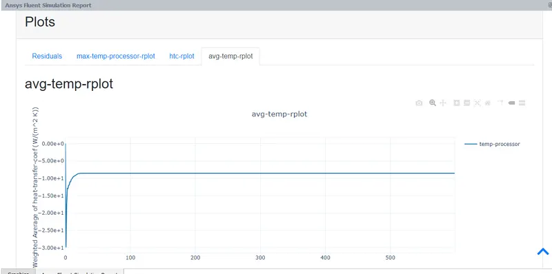
fig: avg-temp-plot
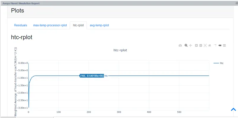
fig: htc plot.
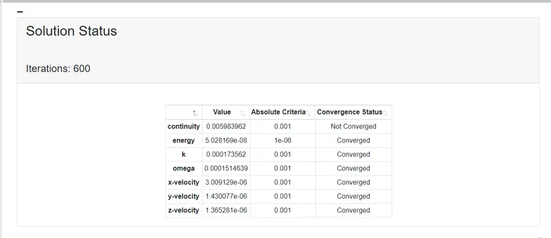
fig: converged
CASE 4 velocity 5m/s ,mesh size 7.5mm.
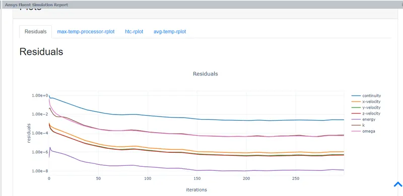
fig= residual plot
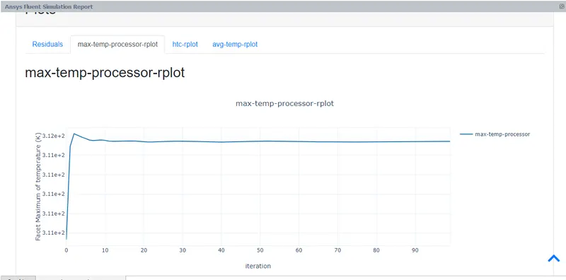
fig: max-temp-plot
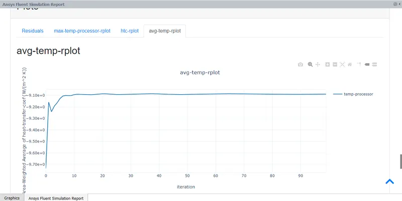
fig: Avg-temperature plot
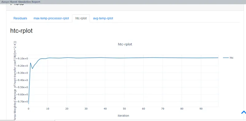
fig: htc plot
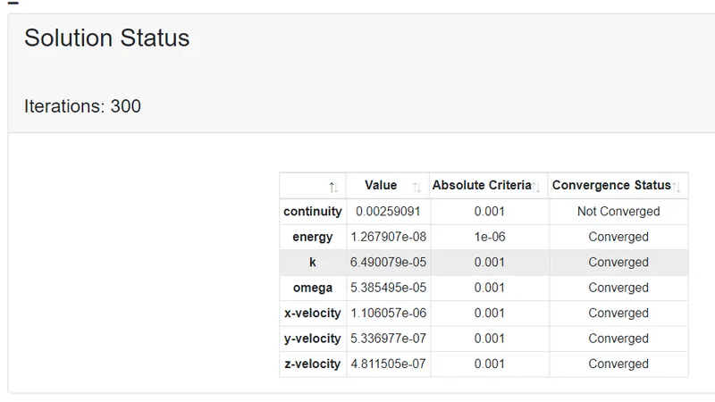
fig: converged
CASE 4 velocity 5m/s and mesh size 6.5mm
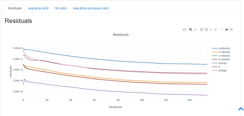
fig: residual plot
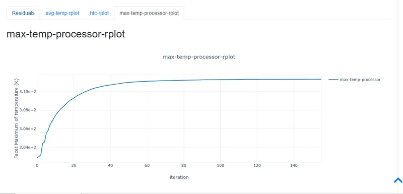
fig: max temperature plot.
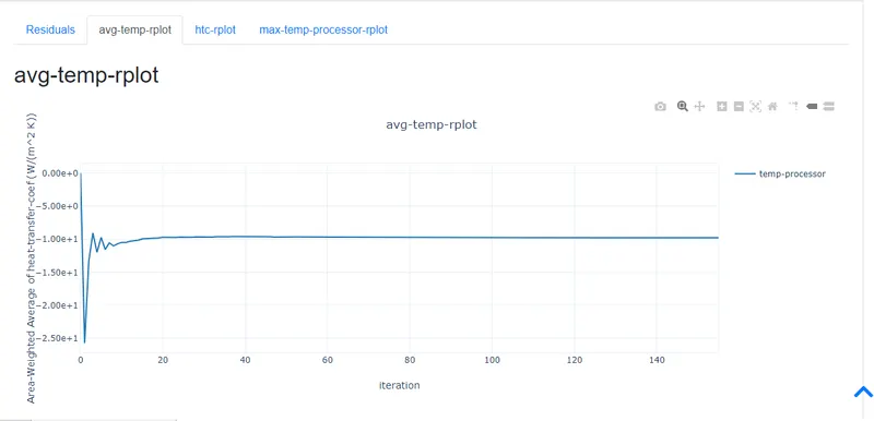
fig: Avg-temperature plot.
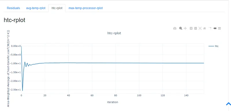
fig: htc plot
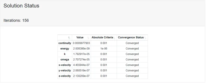
fig: converged
RESULT:
case 1
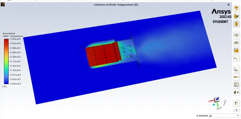
fig: temperature contour.
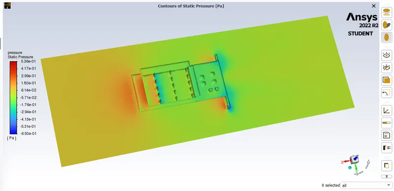
fig: pressure contour
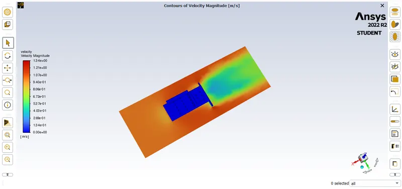
fig: velocity contour.
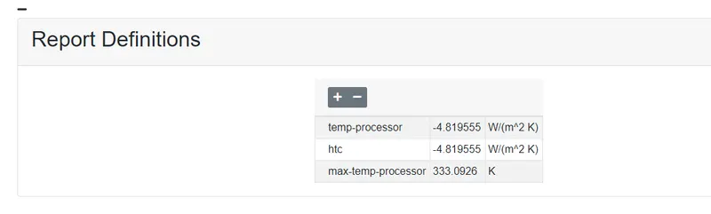
fig: result values
CASE 2
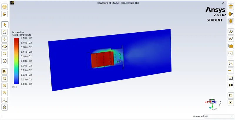
fig: temperature contour
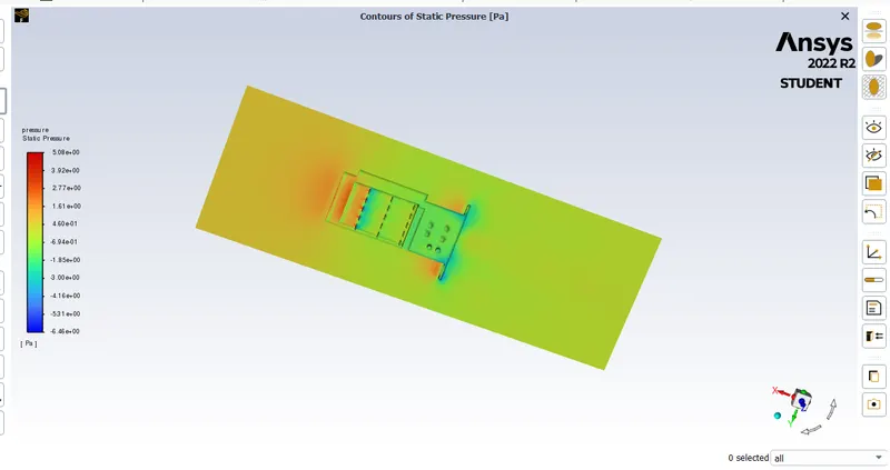
fig: pressure contour
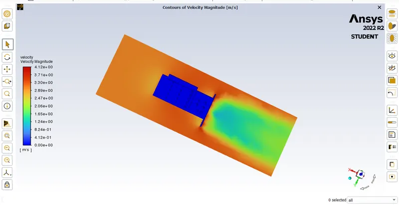
fig: velocity contour

fig: result values.
case 3
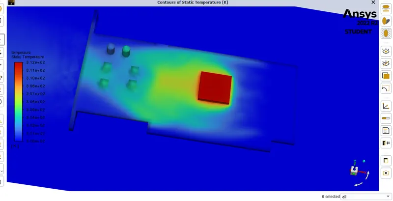
fig: temperature contour with processor.
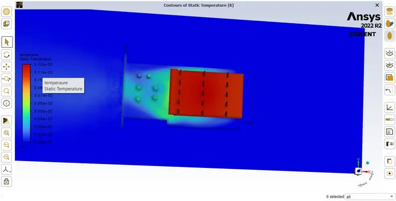
fig: temperature contour
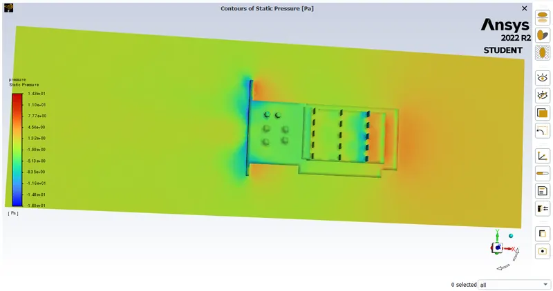
fig: pressure conture
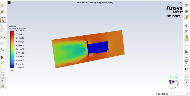
fig: velocity contour
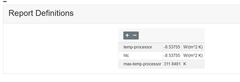
fig: result values
case 4:
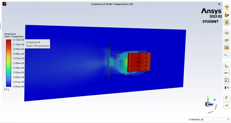
fig: temperature contour
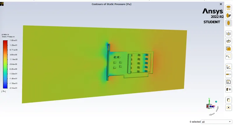
fig: pressure contour
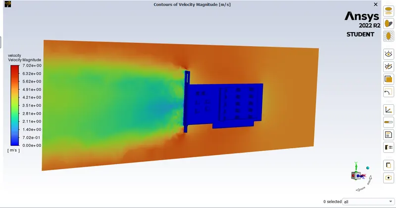
fig: velocity contour
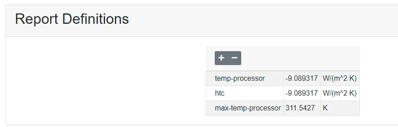
fig: result values
CASE 5
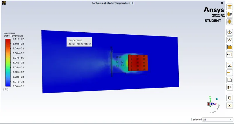
fig: temperature contour
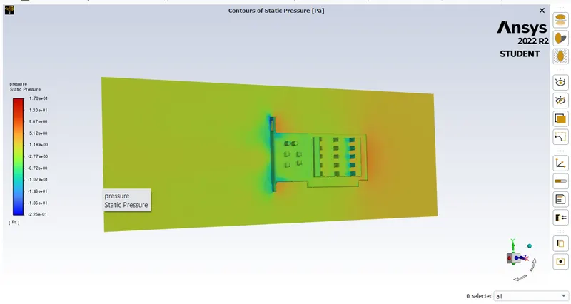
fig: pressure contour
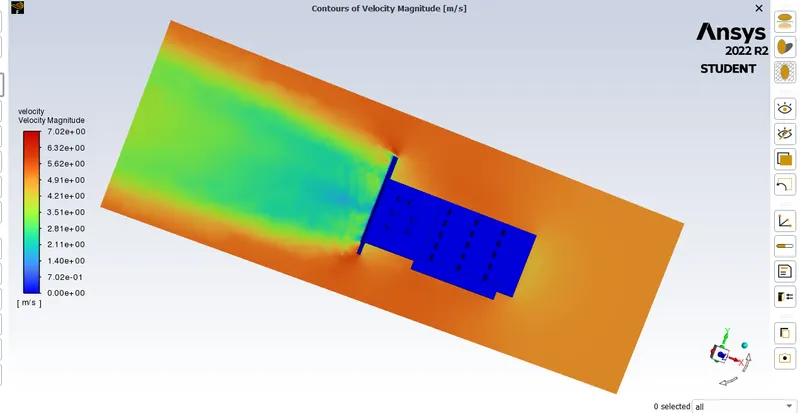
fig: velocity contour.
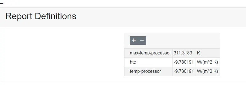
fig: result values
CONCLUSION:
Here i conclude that the velocity increases the temperature of the processor decreases, in the each case the velocity is increase the maximum temperature is going on decreasing. the heat from the processor is transfer to the fins due to this the hotspots are formed on the fins and the processor only remaining part will be less transfer of heat and also their thermal conductivity of the material is also low.